 Europe
  Türkiye
  United Kingdom
  Global


 0
0

To make sure mating cylindrical features work as designed, engineers use a standardised tolerancing system called limits and fits. It defines allowed size variation for a hole and a shaft, and how those variations combine to create clearance, transition, or interference.
This article follows ISO 286-2 terminology; the ASME/ANSI approach uses the same principles with minor wording differences.
Importance of Limits and Fits
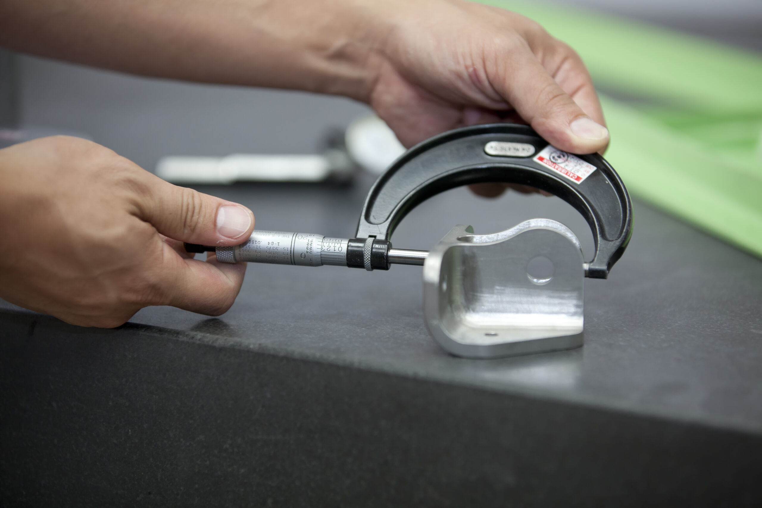
In many assemblies, the gap between smooth operation and costly failure is measured in micrometres. No process produces exact sizes every time.
The limits and fits system provides a framework to define acceptable dimensional variations for mating parts, like a shaft and a hole. This standardisation creates a universal language understood by engineers, manufacturers, and quality teams. Suppliers can communicate their process capabilities (tolerance grades), and designers can specify their exact functional requirements.
Using this system helps achieve several key engineering goals:
- Interchangeability: Helps ensure parts from different batches or suppliers will assemble correctly.
- Functional Performance: Achieves the correct clearance or interference for smooth motion, load transfer, sealing, or durability.
- Cost Control: Prevents over-tolerancing and the unnecessary manufacturing costs associated with excessive precision.
- Ease of Assembly: Helps ensure parts can be joined using the intended method, such as sliding, pressing, or thermal fitting (heating and cooling).
- Reliability and Safety: Reduces the risk of failure from issues like excessive looseness, stress, wear, vibration, or leakage.
- Consistent Quality: Establishes clear, measurable standards for inspection and part acceptance.
- Clear Communication: Provides a universal language (per ISO/ANSI) that removes ambiguity between design, manufacturing, and quality control.
The Width of the Tolerance Zone
Limits and fits define a permissible size range for each feature. When you pair a hole and a shaft, the widths of their ranges determine the feel of the fit, from loose to snug, or in limits-and-fits terms, clearance, transition, or interference.
Tolerances are written as a letter + number (e.g., H7 for a hole, k9 for a shaft).
- The number is the International Tolerance Grade (IT grade). It sets the width of the tolerance zone, independent of where that zone sits relative to the nominal.
- The letter sets the position of the zone; we’ll cover letters next.
Outside of limits and fits, you might specify a dimension like 25 mm ±0.15 mm, which means any measured size inside that band passes inspection. IT grades express the same idea more compactly with a single number tied to nominal size.
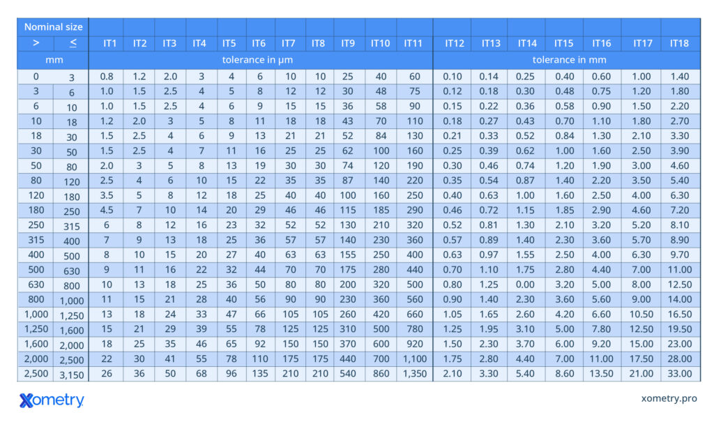
Example. For a 40 mm nominal hole, selecting IT7 gives a zone 25 µm (0.025 mm) wide. That width could be centered on nominal (±12.5 µm) or shifted up or down depending on the letter you choose later. The grade sets only the width.
The limits and fits system uses International Tolerance Grades. The tolerance range is determined by a single number as in the table below.

How to Read the IT Grade Table?
The table links a part’s nominal size to an IT Grade to define the total tolerance width.
The process involves locating the part’s Nominal size range in the left-hand columns. For example, a 40 mm diameter hole falls within the “> 30” to “≤ 50” mm range.
Moving across that row to the selected International Tolerance Grade (IT Grade) column provides the tolerance width. For our 40 mm part, selecting IT7 gives a total tolerance width of 25 µm (or 0.025 mm). Note that the units change from micrometres (µm) to millimetres (mm) for coarser grades (IT12 and higher).
This IT Grade only sets the width, not the position. A 25 µm width for a 40 mm hole could be applied in many ways:
- 40 mm ±0.0125 mm
- 40 mm +0.020 / -0.005 mm
- 40 mm +0.025 / -0.000 mm
The position of this 25 µm zone is set by the letter (like the “H” in H7), which defines the start point.
First, a bit about the applicability of the tolerance grades.
General Applications for Tolerance Grades
| IT Grade(s) | Precision Level | Typical Applications & Examples |
| IT00-IT01 | Ultra-High Precision | Not included in the general table. Typical examples include optical flats and certain aerospace or semiconductor tooling. |
| IT1-IT4 | Extremely Precise | For high-accuracy measuring instruments, precision gauges, and scientific optical equipment. These applications are rare in everyday engineering. |
| IT5 | Very High Precision | Suitable for precision fits where tolerances must be minimal. Typical examples include high-precision gears or gears mounted on shafts. |
| IT6-IT7 | High Accuracy (Common) | Used for fits requiring high accuracy for assembly, movement, and airtightness. Typical examples include standard rolling bearings, common transition or interference fits, medium- and high-precision gears, hydraulic components, and engine crank mechanism parts. |
| IT8-IT9 | Medium Precision | When accuracy demands are not high. Typical examples include low-precision transition fits, clearance fits (especially where form/position deviations must be compensated), and supports for medium-speed shafts. |
| IT10 | Medium/Low Precision | Common when simplifying manufacturing is central and the assembly allows for more slack. Applications are similar to IT8-IT9 but with less precision. |
| IT11-IT12 | Low Precision (Coarse) | In assemblies that require large clearances and where a wide tolerance is acceptable. Examples include non-critical components like covers, flanges, stampings, and agricultural machinery parts. |
| IT13-IT18 | Very Coarse | For non-precision parts.These grades are not often referenced, as most contemporary fabrication methods can achieve higher accuracy.Examples include structural steelwork, weldments, castings, and mining machinery. |
Achieving the Tolerances: Process and Cost
The table below shows what tolerance grade is achievable with each of the listed machining operations.
| Machining operation | Typical IT grades* |
| Lapping, honing | IT4–IT5 |
| Cylindrical grinding | IT5–IT7 |
| Surface grinding | IT5–IT6 |
| Diamond turning / boring | IT5–IT6 |
| Broaching | IT5–IT7 |
| Reaming | IT6–IT10 |
| Turning | IT7–IT13 |
| Boring | IT8–IT13 |
| Milling | IT10–IT13 |
| Planing & shaping | IT10–IT13 |
| Drilling | IT10–IT13 |
*Actual capability depends on size, material, workholding, tool condition, and shop practice.
A quick review shows that standard CNC turning can achieve an IT7 range, while milling is typically in the IT10 to IT13 range.
This higher accuracy from turning is a key reason the hole-basis system (which we will cover next) is generally preferred over a shaft-based system.
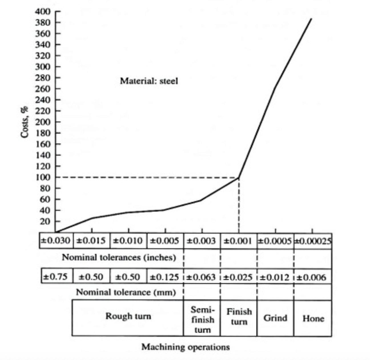
Image source: https://www.cnccookbook.com
The graph below illustrates the exponential relationship between finishing accuracy and manufacturing cost.
It’s important to note that the graph is an illustration and does not show the nominal dimensions. This distinction is crucial because maintaining the same tolerances, such as +/- 0.063 mm, becomes more challenging with larger nominal dimensions. For instance, achieving these tolerances on a 100 mm diameter shaft is more difficult and expensive than on a 30 mm shaft.
Tighter tolerances lead to a rapid increase in manufacturing costs. This is due to the additional time, setups, and inspection required for finishing processes like fine grinding, lapping, and selective rework. The impact on cost is also greater for larger nominal sizes; for instance, maintaining a tolerance of ±0.063 mm on a Ø100 mm shaft is more challenging and expensive than on a Ø30 mm shaft.
The Position of the Tolerance Zone
While the IT Grade number (e.g., the ‘7’ in H7) defines the width of the tolerance zone, the letter (e.g., the ‘H’) defines its position relative to the nominal size.
- Capital letters (e.g., H, G, K) are used for holes (internal features).
- Lowercase letters (e.g., h, g, k) are used for shafts (external features).
In the ISO system, this letter specifies the fundamental deviation, which tells us where the tolerance zone starts in relation to the nominal diameter, or “zero line”. Many common fits use H for the hole or h for the shaft, which means one of the tolerance limits starts exactly at the nominal size.
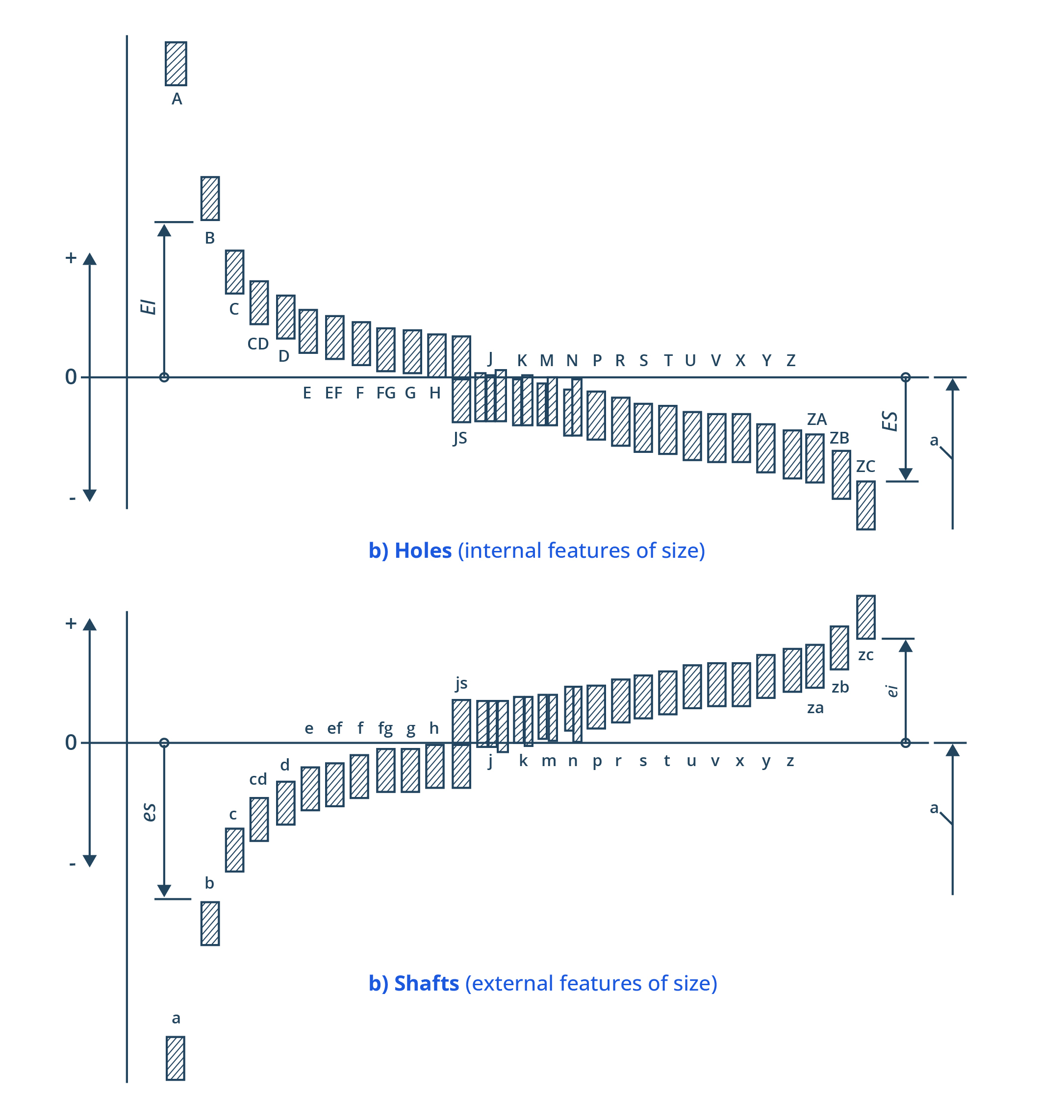
The chart above shows the fundamental deviations for each letter. The letter only defines this starting point (the closest limit to the zero line). The total “length” of the bar (the tolerance interval) is still determined by the IT Grade number (e.g., IT7).
Let’s combine these concepts for a 40H7 hole:
- Nominal Size: 40 mm
- H (Letter): The fundamental deviation for “H” is 0. This sets the lower limit (EI, or Écart Inférieur) at the nominal size.
- 7 (Number): From the IT Grade table (for 30-50 mm), IT7 gives a width of 25 µm.
The 40H7 tolerance zone is now fully defined. The lower limit is 40.000 mm (EI = 0 µm), and the upper limit (ES, or Écart Supérieur) is 40.025 mm (ES = +25 µm).
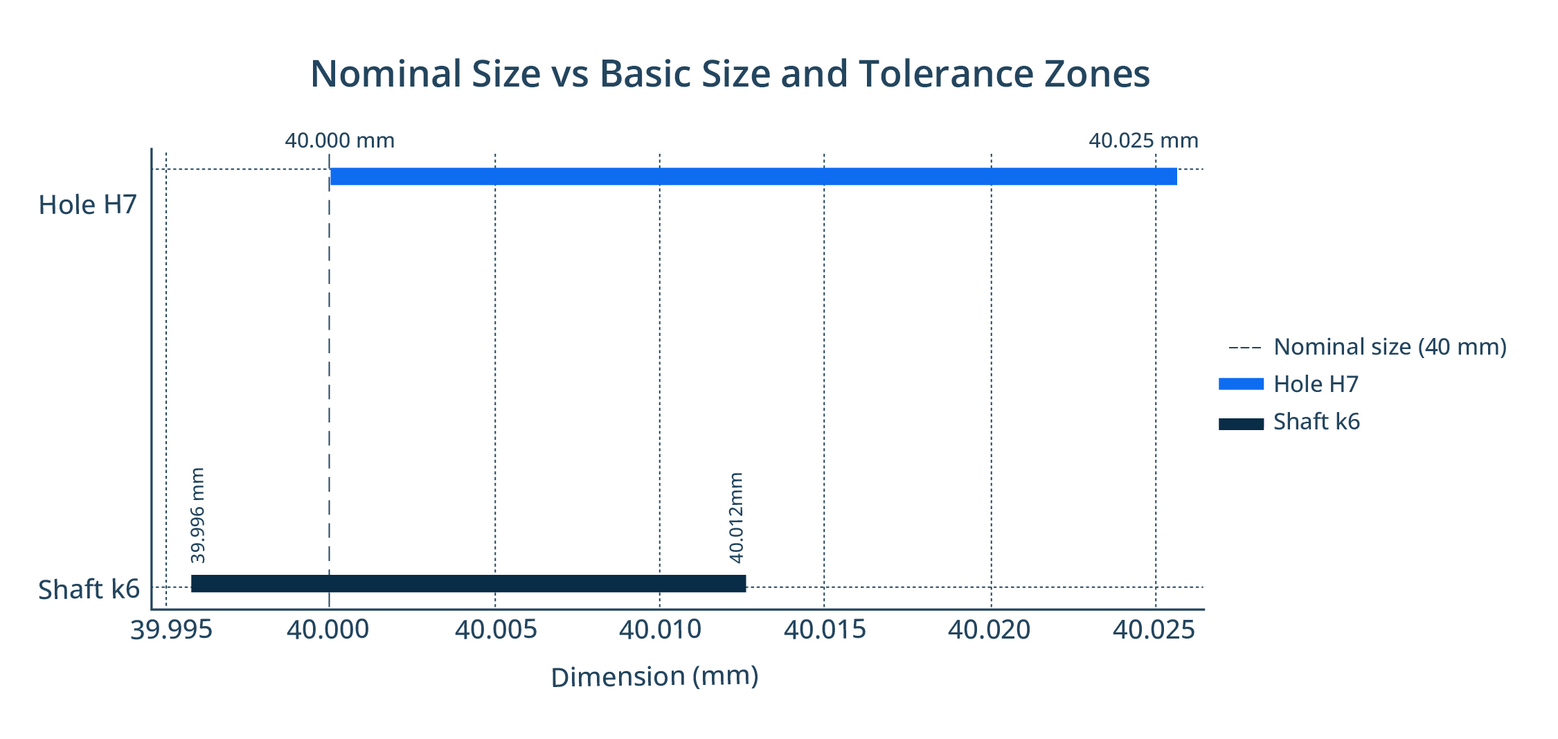
The graph above compares the tolerance zones for a 40H7 hole and a 40k6 shaft. The hole’s minimum size is 40.000 mm, while the shaft’s minimum size is 39.996 mm.
Notice the tolerance zones overlap. Depending on the actual manufactured sizes, the resulting fit could be a small clearance (if the hole is large and the shaft is small) or a small interference (if the hole is small and the shaft is large). This type of fit, which can result in either outcome, is called a transition fit.
Hole-Basis vs. Shaft-Basis Systems
When designing limits and fits, a “basis” must be chosen—either the hole or the shaft. This basis feature has its tolerance fixed, and the mating part’s tolerance is adjusted to create the desired clearance, transition, or interference.
The basis part typically has a fundamental deviation of 0, designated by H for holes or h for shafts.
The Hole-Basis System
In the hole-basis system, the hole’s lower deviation (EI) is fixed at 0 µm. This means the smallest possible hole size is exactly the nominal size, and the tolerance zone extends upwards. The fit is then created by adjusting the shaft’s tolerance zone (e.g., g6, k6, or p6).
The hole-based system is the preferred option for several reasons:
- Manufacturing Flexibility: It is easier and more precise to machine a shaft’s external diameter down (e.g., via turning) than to machine a hole’s internal diameter up (e.g., boring or reaming) to achieve a specific fit. This aligns with the process capabilities discussed earlier.
- Standard Components: Many off-the-shelf parts, such as rolling bearings, are manufactured to an H-basis tolerance. The hole is pre-existing and becomes the fixed basis for the fit.
- Standard Tooling: Standard hole-making tools (like drills and reamers) are designed to produce holes at or slightly above their nominal size, which naturally aligns with the H-basis system. In contrast, CNC turning a shaft offers high flexibility to achieve any required size.
Note that a single measurement (e.g., a bearing hole of 40.009 mm) cannot be reverse-engineered to a specific tolerance grade. That dimension could fall within the tolerance band of H5, H6, or several other designations.
The Shaft-Basis System
In the shaft-basis system, the shaft’s upper deviation (es) is fixed at 0 µm. The shaft’s largest possible size is equal to the nominal size. The fit is then determined by choosing the hole’s tolerance zone.
While the hole-basis system is more common, the shaft-basis system is the logical choice in specific situations:
- When using standard, pre-manufactured stock shafting (e.g., 40h6 or 40h8), the shaft becomes the fixed element.
- If a shaft is difficult to modify, such as after heat treatment resulting in high hardness, it may be easier to treat it as the basis and machine the hole to match.
| Scenario | Basis to prefer | Why | Caveats |
| New design; both parts machined in-house | Hole-basis (H7/H8 with g/k/m shaft) | Easier to hit with drills/reamers; shafts can be tuned by turning/grinding | Hole enlargement is costly if rework is needed |
| Uses a purchased bearing or bushing | Hole-basis | Vendor bores are effectively H-basis | Verify vendor’s actual bore tolerance before pairing |
| Using stock ground bar (e.g., h6) | Shaft-basis | Off-the-shelf shafts define the fit | Hole must be positioned/graded to suit |
| Shaft hardened/finished before fitting | Shaft-basis | Hard rework is risky/expensive | Plan hole process capability accordingly |
| Tightest location accuracy with press assembly | Either; commonly H7/m6 (hole-basis) | Easier assembly control with fixed hole baseline | Confirm press/thermal assembly plan |
Types of Fits
There are three categories of engineering fits: clearance fit, transition fit, and interference fit.
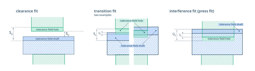

The fit between mating parts, like a shaft and a hole, depends on the relative position of their tolerance zones. This determines the amount of room or interference between them. The image above shows the three types, with the transition fit depicted at its maximum clearance and maximum interference extremes.
The examples in this section are hole-based (e.g., “H7”), but shaft-based equivalents also exist.
Clearance Fit
A clearance fit is a fit where the hole will always be bigger than the shaft, even at the tightest limits of their tolerance zones. This ensures the assembly is easy, does not require force, and allows for free movement between the parts.
Clearance fits are common when:
- Free motion or low-friction movement is necessary.
- Easy assembly and disassembly are required.
- Thermal expansion must be accounted for to prevent binding.
Clearance fits are classified as loose running, free running, close running, and sliding fits.
| Fit Type | Feel & Characteristics | Hole-Basis Examples | Typical Applications |
| Loose Running | Large ClearanceAccuracy is not important; free movement must be guaranteed under adverse conditions (dirt, heat). | H11/c11, H11/d11, H9/d9 | Agricultural machinery joints, loose guide rods, rough machine parts. |
| Free Running | Moderate ClearanceParts must move freely with no risk of jamming, even with some thermal expansion. | H9/e9, H9/f9, H8/f8 | Pulleys on shafts, light-duty sliding mechanisms, low-precision gear shafts. |
| Close Running | Small ClearanceFor accurate alignment with minimal play; suited for precision rotary movement. | H7/h6, H7/h5 | High-speed shafts, precision spindles, lightly loaded bearings. |
| Sliding Fit | Very Small Clearance For accurate location where parts must slide with minimal play. | H8/g7, H7/g6 | Machine tool slides, accurate guide rails, lightly loaded spindles. |
Transition Fit
A transition fit is a fit where the tolerance zones of the hole and shaft partly overlap. This means the final assembly might result in a small clearance or a small interference, depending on the actual manufactured sizes.
A transition fit is a good choice when the design must compromise between location accuracy and ease of assembly.
Transition fits are common when:
- Parts must be accurately located, but assembly must still be relatively easy.
- A small amount of either clearance or interference is acceptable.
- Dimensional control is high, but a full force-fit is not necessary
Transition fits are classified as free, similar and tight fits.
| Fit Type | Feel & Characteristics | Hole-Basis Examples | Typical Applications |
| Free Fit | Tendency toward ClearanceAccurate location, but with a high probability of clearance. Parts can be assembled without pressing. | H7/j6, H8/j7 | Sliding spigots, changeable sleeves, positioning pins. |
| Similar Fit | Balanced clearance/interference (C/I)Accurate positioning where parts may be assembled by light force or hand tapping. | H7/k6, H7/k5, H6/k5 | Gear wheels on shafts, couplings, machine tool arbors. |
| Tight Fit | Tendency toward InterferenceParts are intended to be fixed with minimal movement under normal conditions. | H7/m6, H7/m5, H7/m4 | Electric motor rotors on shafts, lightly loaded hubs, locating sleeves. |
Interference Fit
An interference fit is a fit where the hole will always be smaller than the shaft, creating a solid interference. This class of fit requires force for assembly, often combined with thermal methods (heating the hole for expansion, cooling the shaft for contraction). Disassembly often requires machining.
Interference fits are common when:
- The joint must transmit significant torque or axial load without slipping.
- The assembly requires precise, rigid, and permanent location.
- There must be no movement between mating surfaces.
Interference fits are classified as press, driving and forced interference fits.
| Fit Type | Feel & Characteristics | Hole-Basis Examples | Typical Applications |
| Press Fit | Small InterferenceCan be assembled with moderate force. Secure location, but disassembly is possible. | H7/p6, H7/p5, H8/p6 | Pulley hubs, lightly loaded gears, keyed shafts where the fit prevents wobble. |
| Driving Fit | Strong GripOften requires thermal assembly. Used for heavy-duty connections subject to vibration and shock. | H7/s6, H7/s5 | Transmission gears, railway wheel seats, couplings in heavy machinery. |
| Forced Fit | Maximum Grip Considered permanent. Disassembly is often impossible without damaging the parts. | H7/u6, H7/u5 | Aircraft engine parts, press-fitted crankshaft gears, turbine shafts. |
Design Checklist for Specifying a Fit
Limits and fits are a critical tool for ensuring assemblies function as intended. If chosen correctly, they provide a clear, standardised language for design, manufacturing, and inspection.
Use the following points as a checklist when specifying a fit:
- Choose Your Basis: Decide on a Hole-Basis (preferred) or Shaft-Basis system. This choice depends on available standard components (like bearings or stock shafts), tooling, and manufacturing ease (e.g., material, heat treatment).
- Select Fit Type: Determine the required function for the joint: Clearance (for free movement), Transition (for precise location), or Interference (for rigid, permanent assembly).
- Select the Fit Combination: Consult “preferred fits” tables to select a standard hole/shaft combination (e.g., H7/k6, H7/p6, H9/d9). This balances functional requirements with standard manufacturing practice and cost.
- Calculate and Verify Limits: Always calculate the minimum and maximum clearance (for clearance/transition fits) or interference (for interference/transition fits). Use a reliable limits and fits calculator to verify your chosen combination.
- Confirm Manufacturability (DFM): Check that your chosen IT Grade (the number) is achievable and economical for your supplier’s processes. Tighter grades (e.g., IT5-IT6) require precision operations like grinding and add significant cost.
- Plan for Assembly: For transition and interference fits, confirm the assembly method. Ensure the required force (for pressing) or thermal procedures (for heating/cooling) are practical and will not damage the components.


Comment(0)