 Europe
  Türkiye
  United Kingdom
  Global

ISO 286 Limits and Fits Calculator
Calculate standard limits and fits according to ISO 286. Enter your nominal size to determine precise tolerance ranges for mating parts.
Identify clearance, transition, and interference fits for accurate mechanical design.
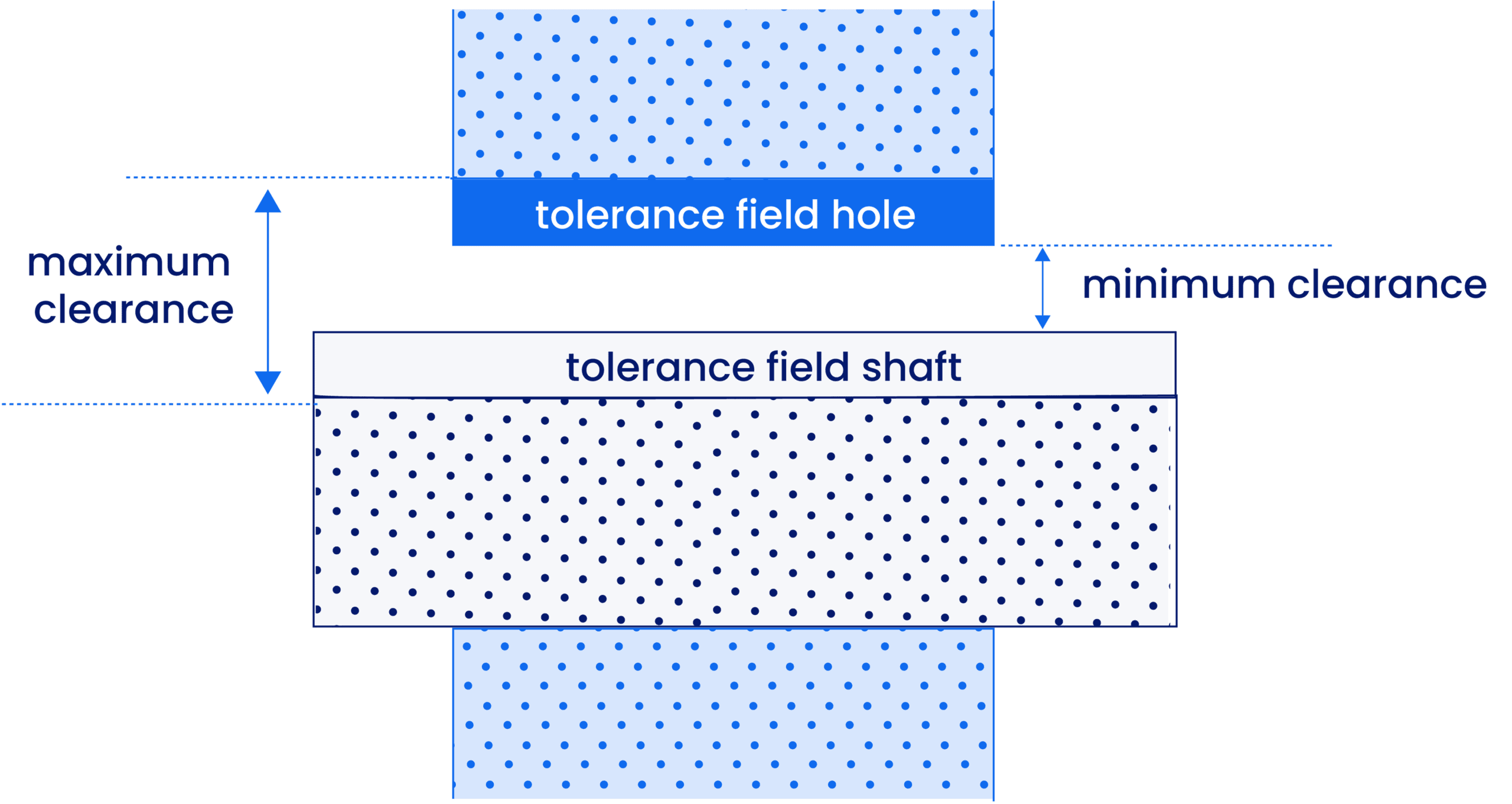
Clearance Fit
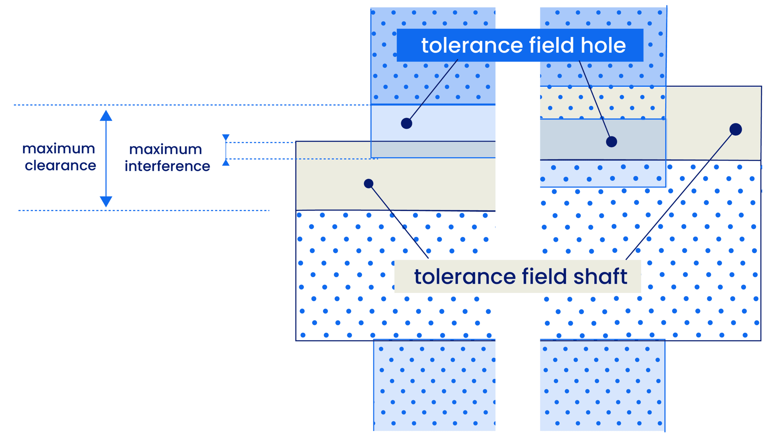
TRANSITION FIT
The tolerance zones of the hole and shaft overlap. Depending on the final machined dimensions, the assembly may result in either a slight clearance or a slight interference. Used for precise location and alignment.
FAQ
What are limits and fits in engineering?
Limits and fits define the dimensional tolerances required for two mating parts—typically a shaft and a hole—to assemble and function correctly. Limits are the maximum and minimum size constraints for a single part. The fit describes the resulting relationship (tightness or looseness) between the two parts when assembled.
What is the ISO 286 standard?
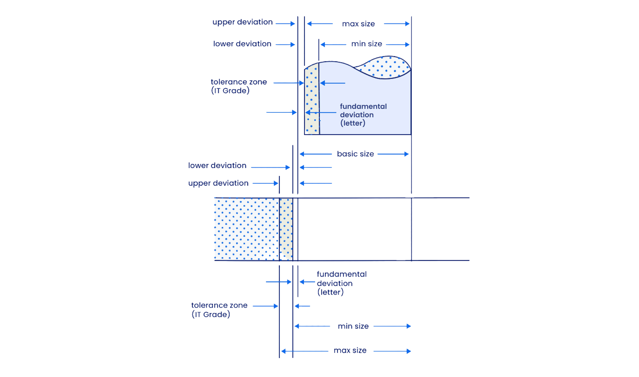
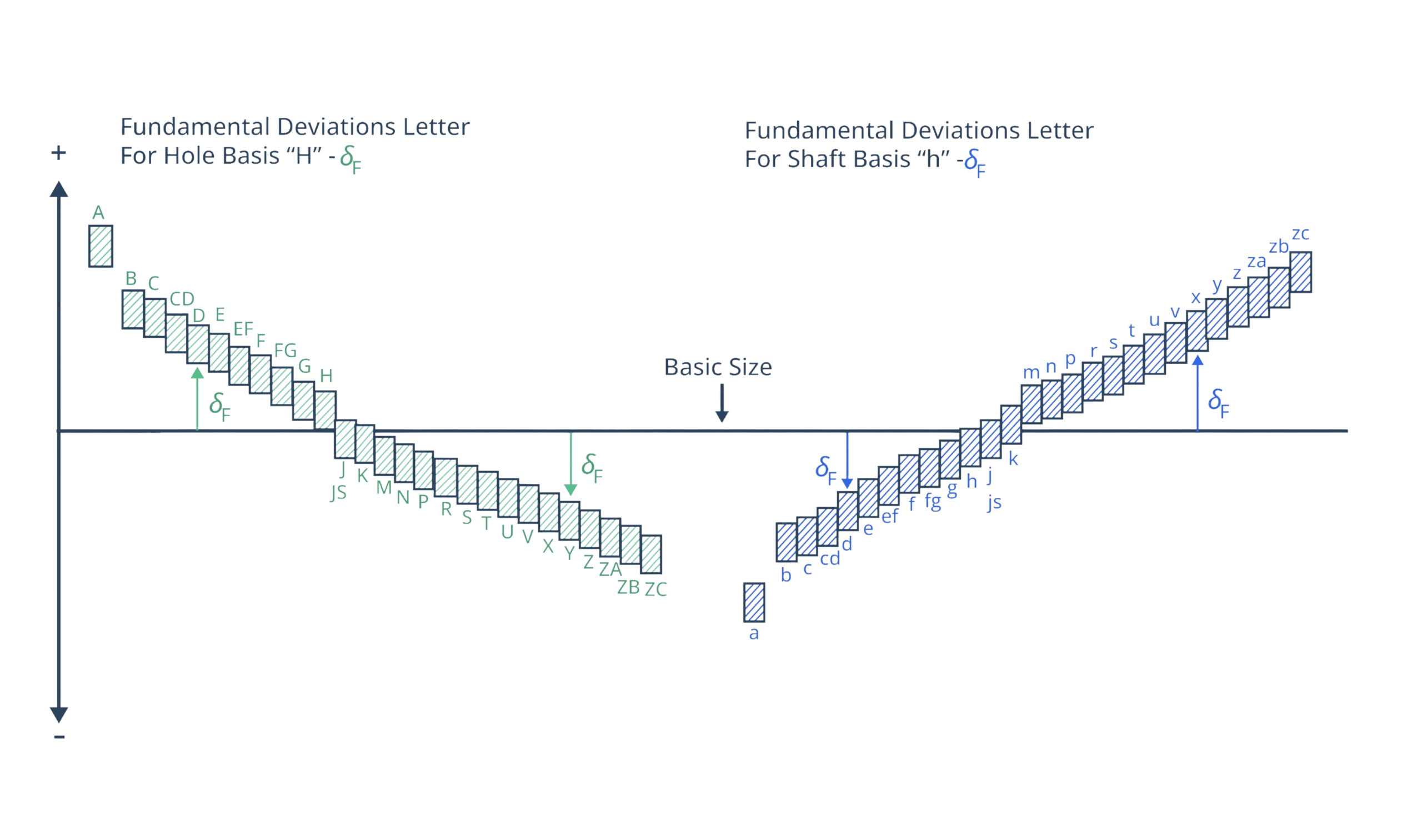
ISO 286 is the international reference for linear tolerances. It uses an alphanumeric system (e.g., H7/g6) to define the fundamental deviation (the letter, indicating position relative to the nominal size) and the International Tolerance (IT) grade (the number, indicating the size of the tolerance zone).
What is the difference between a Hole Basis and a Shaft Basis system?
Both systems are methods used to achieve a specific fit (Clearance, Transition, or Interference), but they differ in which part remains “fixed” as the standard reference.
- Hole Basis System: The hole’s minimum size is kept constant at the nominal dimension (denoted by an uppercase H). The size of the shaft is varied to achieve the desired fit.
- Shaft Basis System: The shaft’s maximum size is kept constant at the nominal dimension (denoted by a lowercase h). The size of the hole is varied to change the fit.
Why is the Hole Basis system more common in manufacturing?
The Hole Basis system is the industry standard because it is significantly more cost-effective and easier to manufacture. Machining a hole requires fixed-size tooling like drill bits and reamers. It is much easier to buy standard-sized tooling for the hole and adjust the exterior diameter of the shaft on a CNC lathe to achieve the specific fit.
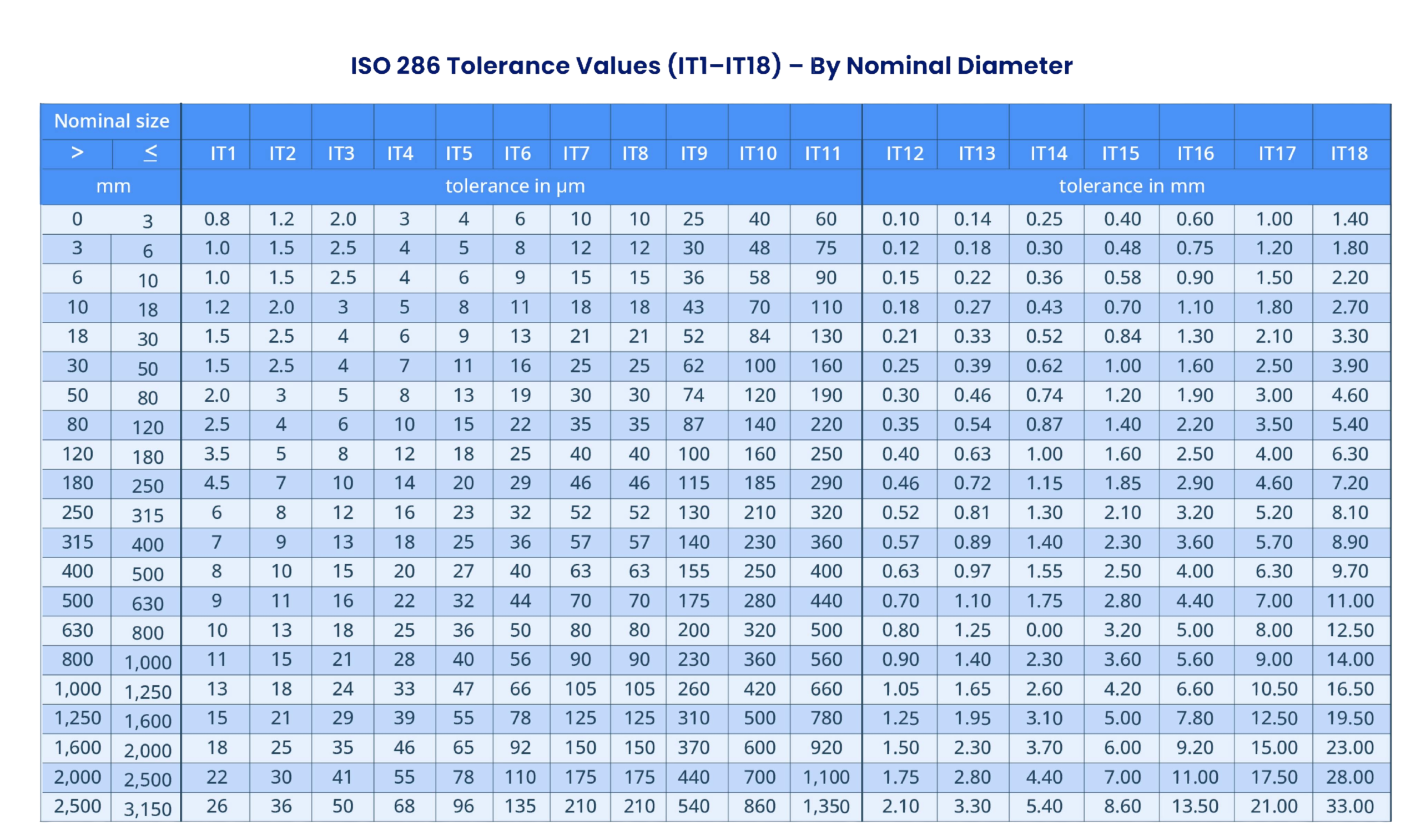
How do I choose the right International Tolerance (IT) grade?
IT grades determine the precision level and manufacturing cost. Lower numbers represent tighter tolerances. Use the table below as a guide for selecting the correct grade for your application:
| IT Grade(s) | Precision Level | Typical Applications & Examples |
| IT01 – IT0 | Ultra-High Precision | Optical flats, aerospace, and semiconductor tooling. |
| IT1 – IT4 | Extremely Precise | High-accuracy measuring instruments, slip gauges, and scientific optics. |
| IT5 | Very High Precision | Precision fits, machine tool spindles, and high-precision gears. |
| IT6 – IT7 | High Accuracy | Bearings, hydraulic components, and engine crank mechanisms. |
| IT8 – IT9 | Medium Precision | Low-precision transition fits and supports for medium-speed shafts. |
| IT10 | Medium / Low Precision | Non-critical rotating parts where manufacturing simplicity is key. |
| IT11 – IT12 | Low Precision (Coarse) | Covers, flanges, sheet metal stampings, and agricultural machinery. |
| IT13 – IT18 | Very Coarse | Structural steelwork, heavy weldments, and sand castings. |
When should I use a Clearance Fit (e.g., H7/g6 or H8/f7)?
Clearance fits are used when parts need to move relative to one another. There is always a gap between the shaft and the hole.
- Slide Fit (H7/g6): Used for precise location and where parts must slide freely.
- Running Fit (H8/f7): Ideal for rotating shafts or bearings where lubrication is required.
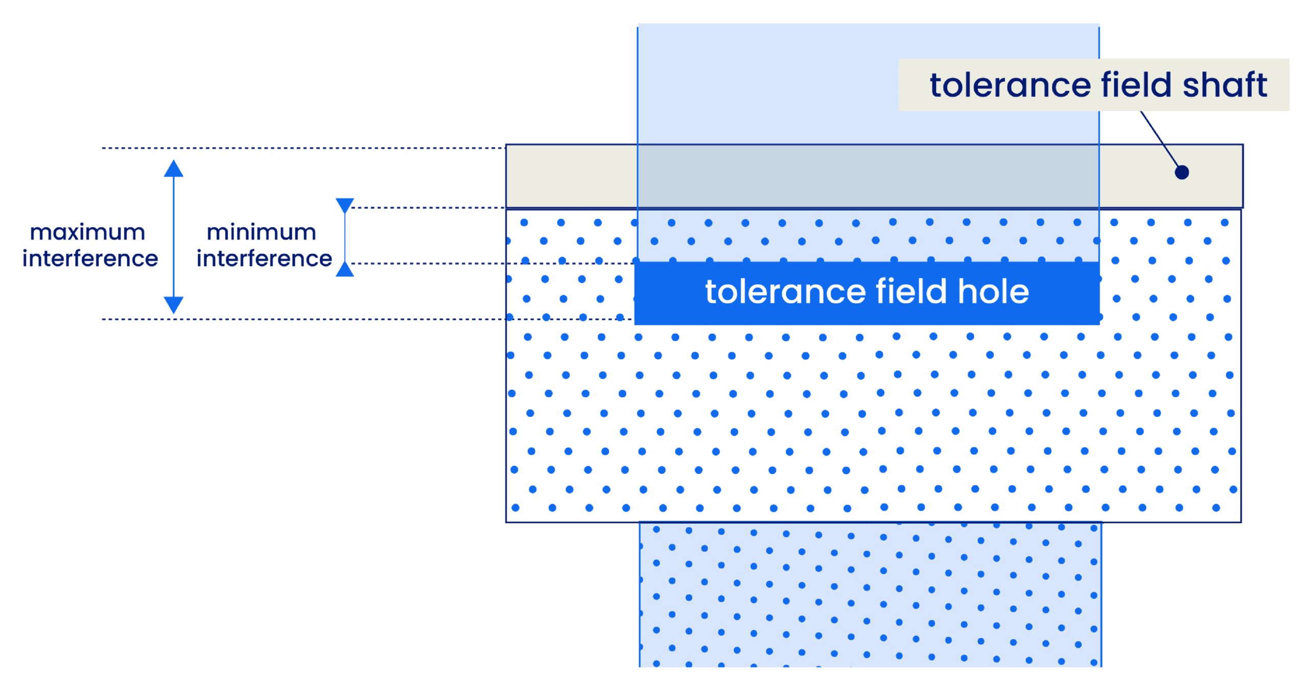
When is an Interference (Press) Fit required (e.g., H7/p6)?
An interference fit is used when two parts must be joined as a single rigid unit without fasteners. The shaft is slightly larger than the hole, requiring force, heat (expansion), or cold (contraction) for assembly. These are common for bush bearings, gears on shafts, and valve seats.
What is a Transition Fit and when is it used (e.g., H7/k6)?
A transition fit is a “middle ground” where the result can be a slight clearance or a slight interference. These are used for high-accuracy location where parts must be assembled or disassembled easily with a rubber mallet, such as dowel pins or gear hubs that require frequent maintenance.
How do I read a fit callout like "25 H7/g6"?
This callout follows the ISO system of limits and fits, providing the manufacturer with the exact dimensions and tolerances for mating parts:
- 25: The nominal (basic) size in millimeters.
- H7 (The Hole Tolerance):
- Uppercase Letter: Indicates the tolerance refers to the Hole.
- Letter (H): Represents the Fundamental Deviation, which defines the position of the tolerance zone relative to the basic size.
- Number (7): Represents the IT Grade (International Tolerance grade), which defines the magnitude or “width” of the tolerance zone.
- g6 (The Shaft Tolerance):
- Lowercase Letter: Indicates the tolerance refers to the Shaft.
- Letter (g): Represents the Fundamental Deviation.
- Number (6): Represents the IT Grade.
Why use a limits and fits calculator instead of manual tolerance tables?
Manual calculation requires cross-referencing multiple complex ISO charts, which is time-consuming and prone to human error. A limits and fits calculator automates this by instantly providing maximum/minimum sizes and deviations for any nominal dimension, ensuring your CAD drawings and manufacturing specs are 100% accurate.


 0
0