 Europe
  Türkiye
  United Kingdom
  Global

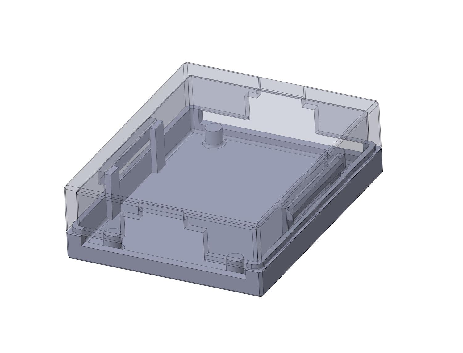
Ejector pin placement near snap-fit
M
I’m working on a small injection-molded housing for an automotive sensor, using PA6 GF30. There are two snap-fit arms inside (cantilever type), about 2 mm-thick walls. I’m not sure where to place the ejector pins without risking marks or deformation near those arms. Anyone here dealt with ejector placement on flexible features like this? Especially with glass-filled nylons that don’t forgive much?

Suggested Topics
Topic
Replies
Views
Activity
DFM check: Is this part a “nightmare” to machine?
Hi! Designing a custom housing for a prototype. I’ve got features on all six sides, and I’m realizing this is going to need a ton of CNC setups. In your experience, is it better... read more
12
62
Apr 05
Robust actuator-to-brake pedal joint for angled, high-force actuation
hi, i am designing a push-rod connection between a linear actuator and a vehicle brake pedal for a durability test setup. The actuator can apply 750 N, and the pedal rotates through its travel,... read more
12
251
Mar 16
Flatness GD&T for 6061 plates
For a mounting plate for a precision sensor (about 200 mm × 200 mm) I was going to call out a flatness of 0.05 mm, but my senior engineer says that’s overkill and will double the machining... read more
3
473
Mar 14
ISO 2768-mK vs specific tolerances
Hey guys, I’m getting some pushback from our shop lead. I’ve been dimensioning every single feature on a new manifold block because I’m paranoid about fitment, but he says the drawing is "unreadable" and... read more
2
629
Mar 14