 Europe
  Türkiye


ASME Y14.5 defines five categories of GD&T tolerances based on the feature aspects they control – form, orientation, location, profile and runout.
Within each category are several different tolerances. Parallelism, alongside angularity and perpendicularity, belongs to the orientation category, where all tolerances control the angular relationships between features.
What is Parallelism (GD&T)?
Parallelism is an orientation tolerance in GD&T that maintains a feature (a plane, axis, or center plane) equidistant from a reference plane or axis along its entire length (a 0° alignment). In simple terms, it ensures that the plane or axis under control is maintained strictly parallel to one or more datum planes or axes.
Because it strictly controls orientation and not location, the feature must maintain a constant distance from the datum along its length, regardless of where it is physically placed in space.
Parallelism can be applied to three primary feature types:
- Surface Parallelism: Maintains a surface parallel to a reference surface, which is typically a mating surface. This is the most common application.
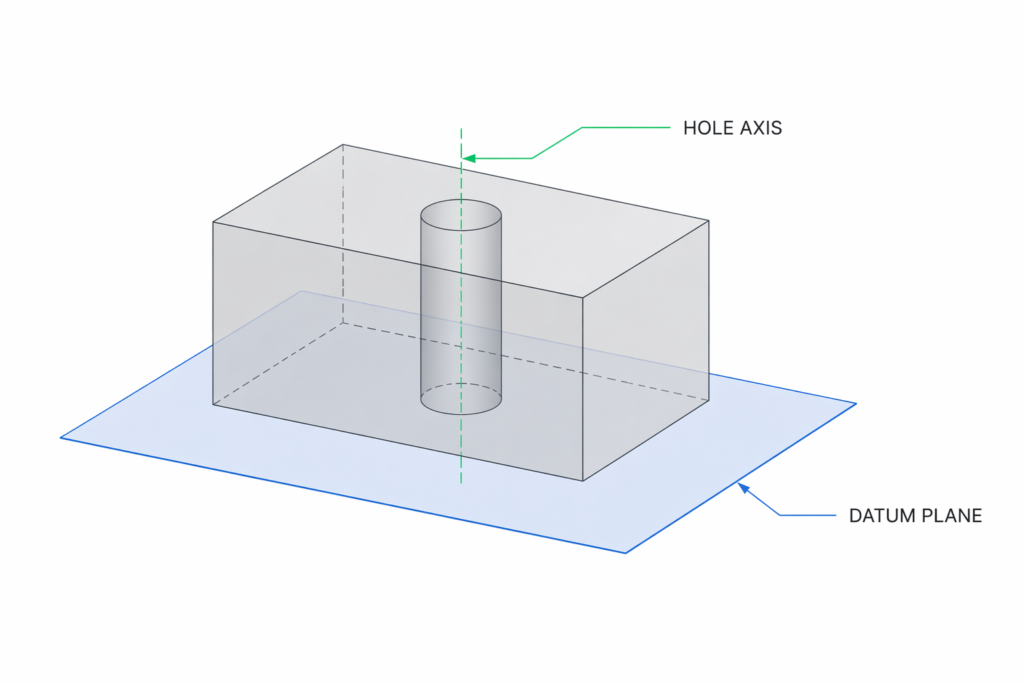
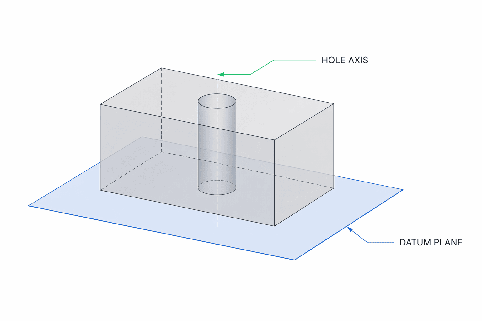
- Axis Parallelism: Controls the central axis of features of size, like pins and holes.
- Center Plane Parallelism: Controls the median plane of features (like slots and tabs) parallel to another surface. The median plane is obtained by averaging the ordinates across the area of these features.
However, selecting parallelism is not always the correct choice. The table below helps engineers quickly decide when to use it.
| Functional goal | Use parallelism? | Better alternative if not |
| Keep a face aligned to a datum surface | Yes | Flatness if only local shape matters |
| Keep a hole axis parallel to a base | Yes | Position if axis location is also critical |
| Keep a surface at 30° or 45° to a datum | No | Angularity |
| Keep a surface shape flat without reference to another feature | No | Flatness |
Engineer Tips
- Do NOT use parallelism when location matters → use position
- Do NOT use parallelism to control flatness → use flatness
- Use axis parallelism only if rotation/fit depends on alignment
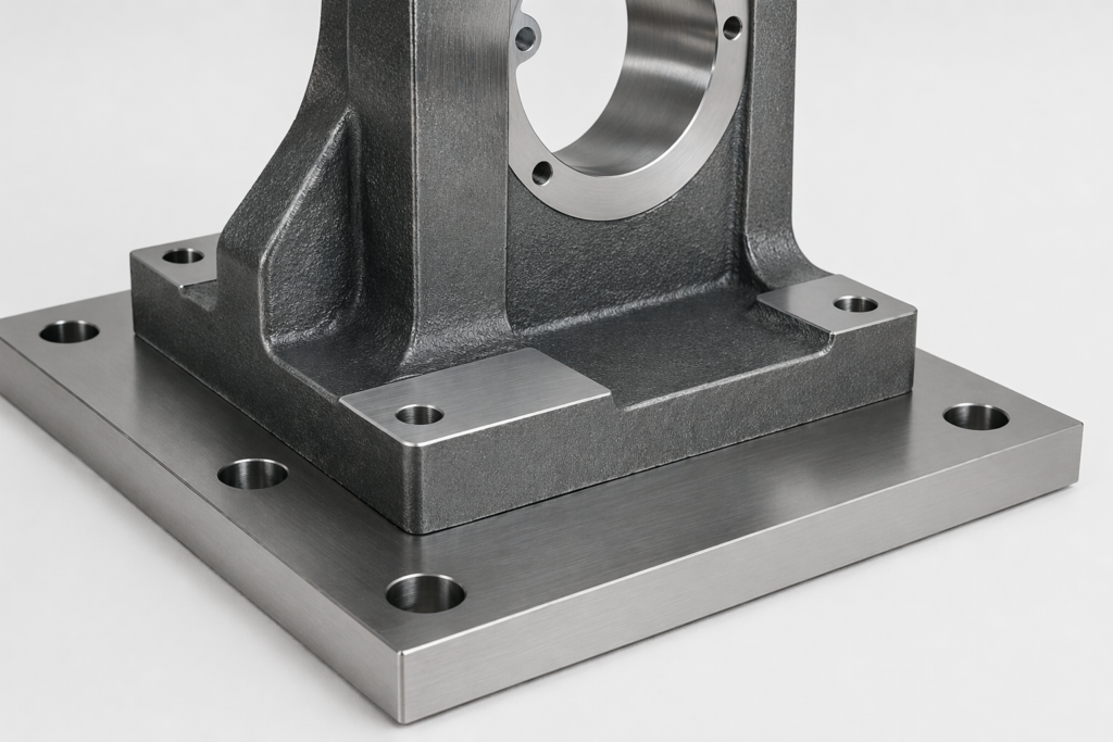
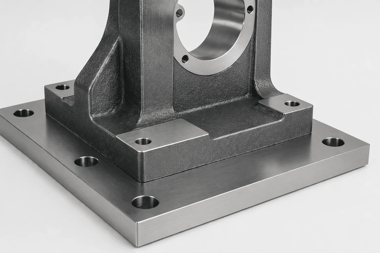
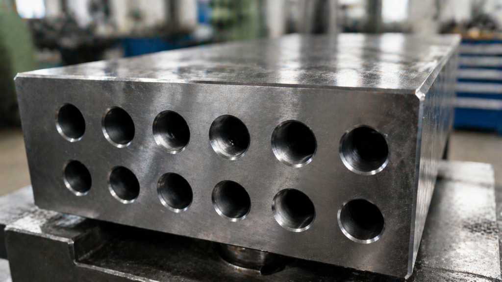
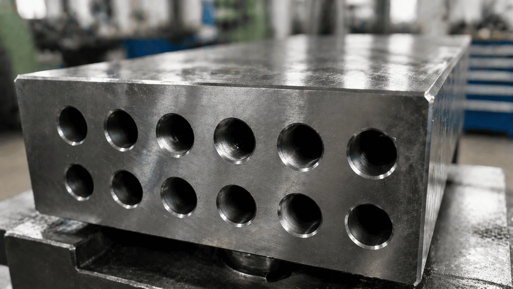
Example: Flange Joints
The parallelism callout is frequently used to align flange faces in industrial piping. The mating flanges must be parallel within a specified tolerance to ensure a properly aligned, leak-proof joint.
While offset misalignment is controlled by position or coaxiality, angular misalignment is primarily controlled by parallelism (often supplemented by flatness or surface profile). By applying a parallelism tolerance to one flange face and using the other as the primary datum, engineers ensure a uniform load distribution among bolts, an evenly pressed gasket, and a minimum risk of failure.
The Parallelism Tolerance Zone
The parallelism tolerance zone is a physical boundary that defines the allowable variation in the controlled surface. The part will fit and function satisfactorily as long as all the points on the controlled feature lie within this zone.
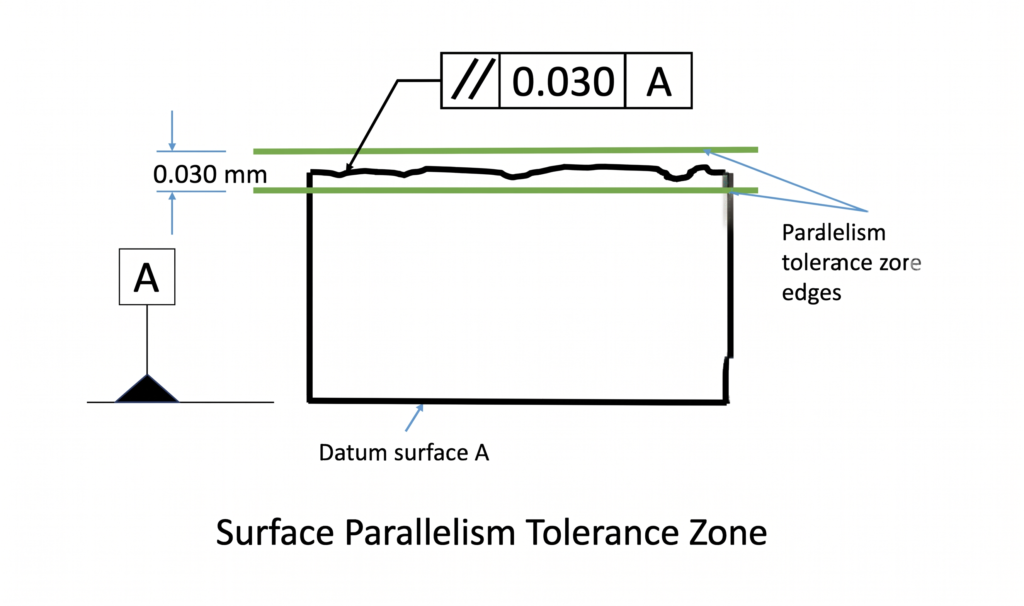
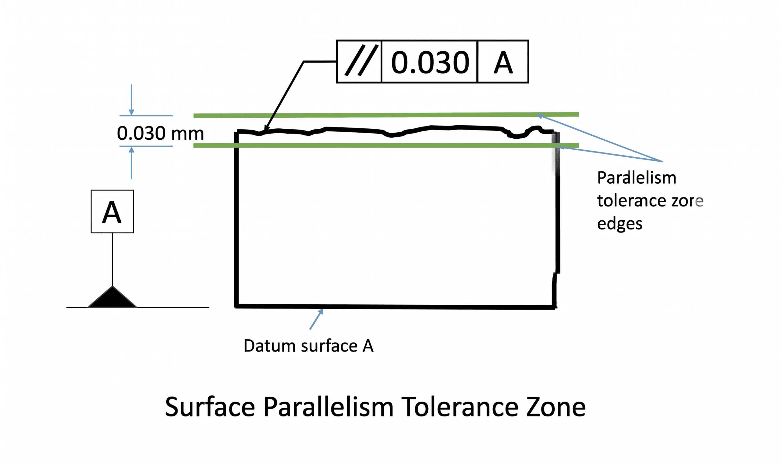
- For Surface and Center Plane Parallelism: The tolerance zone defaults to two parallel planes. The distance between these planes is the tolerance limit. For example, if a surface parallelism tolerance is 0.05 mm, all points on that surface must lie within two parallel planes spaced exactly 0.05 mm apart.
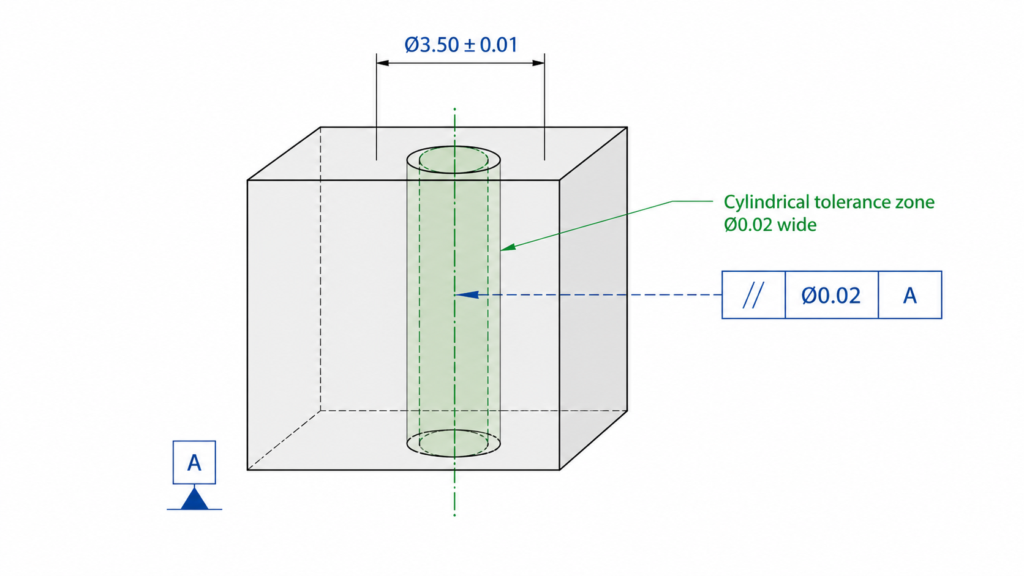
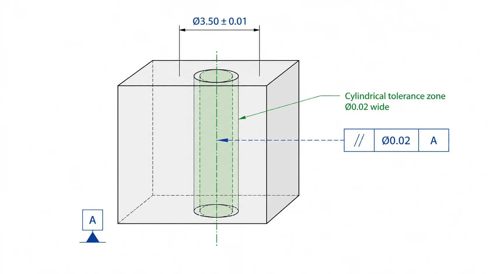
- For Axis Parallelism: The tolerance zone is a cylindrical envelope defined around the derived median axis. For the part to pass inspection, all axis points must lie entirely within this cylinder.
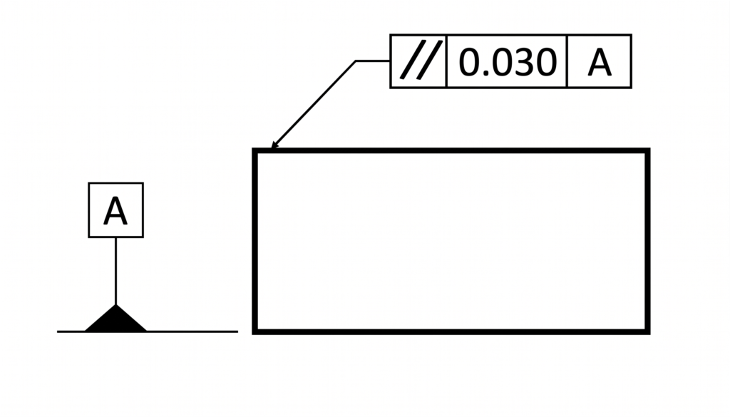
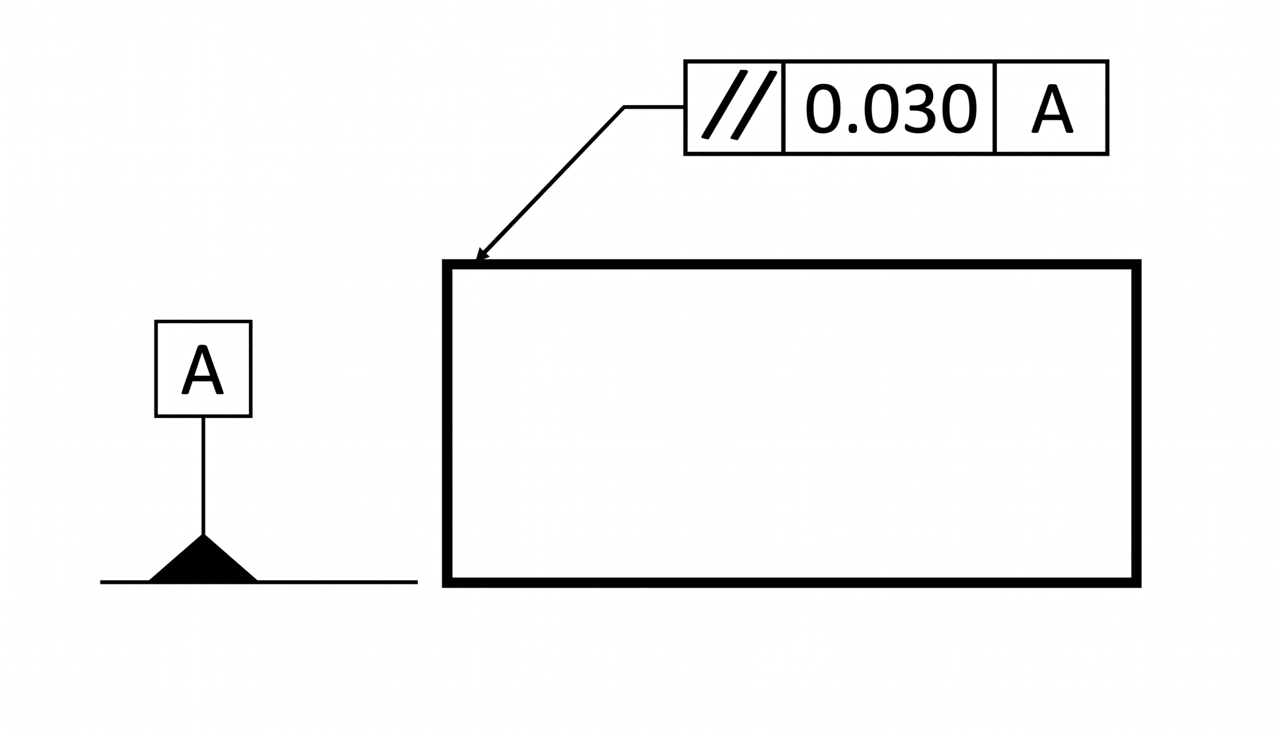
Anatomy of the Parallelism Feature Control Frame
The parallelism tolerance is applied to a CAD drawing using a feature control frame. This frame consists of three distinct blocks: the GD&T symbol block, the tolerance block, and the datum block.
The GD&T parallelism symbol (per ASME Y14.5) consists of two parallel lines angled at approximately 60° from the horizontal.
1. The GD&T Symbol Block
This block informs the user of what geometrical tolerance is being applied. Every tolerance in GD&T has a specific symbol placed in this first block. The GD&T parallelism symbol per ASME Y14.5 consists of two parallel lines that are angled at approximately 60° from horizontal.
2. The Tolerance Block
This block describes how the tolerance is applied, defining the zone shape, value, and material condition.
- Zone Shape: For axis parallelism, a diameter symbol (Ø) is used to specify a cylindrical zone. Surface parallelism uses two parallel planes, which is the GD&T default and requires no special symbol.
- Tolerance Value: This signifies either the diameter of the cylinder (for axes) or the distance between the two planes (for surfaces). Per GD&T Rule #1 (the envelope principle), the parallelism tolerance cannot exceed the specified size tolerance of the feature.
- Material Modifiers: Material condition modifiers (MMC or LMC) can apply to axis and center plane parallelism to control features of size (like holes or pins). Since these modifiers depend on size, they are invalid for flat surfaces. Per ASME Y14.5, if no modifier is specified, the tolerance defaults to Regardless of Feature Size (RFS).
3. The Datum Block
Because parallelism is an orientation control, it requires a reference feature (datum) to check against. The datum defines the reference orientation and restricts the degrees of freedom of the controlled feature.
The datum is housed in the datum block, which is right after the tolerance block.
- Surface and center plane parallelism require only one datum.
- Axis parallelism may require one or two datums, depending on part complexity.
- Parallelism is typically never specified with three datums. The largest and most stable surface is generally selected as the primary datum. It is possible to use multiple primary or secondary datums. When two primary or secondary datums are referenced, such as A and B, they are specified together in the same feature control frame block, separated by a hyphen (A-B).
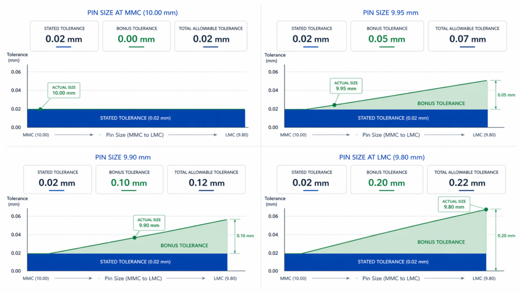
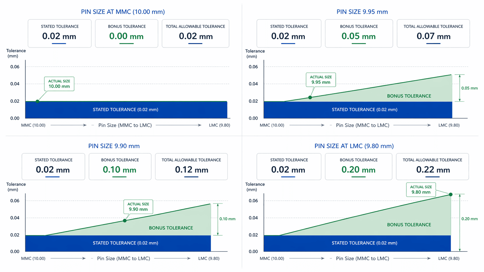
Understanding Bonus Tolerance
When axis or center plane parallelism is utilized alongside an MMC or LMC modifier, it becomes eligible for bonus tolerance.
Bonus tolerance is an additional allowable error in parallelism that occurs when a feature of size departs from the material condition specified in the feature control frame. It is calculated as the difference between the actual measured size and the MMC/LMC size.
- For Internal Features (Holes): Bonus tolerance is gained as the physical size increases. (e.g., A hole with an MMC of 10.00 mm and an actual size of 10.10 mm gains a 0.10 mm bonus tolerance ).
- For External Features (Pins): Bonus tolerance is gained as the physical size decreases. (e.g., A shaft with an MMC of 10.00 mm and an actual size of 9.90 mm gains a 0.10 mm bonus tolerance ).
The total allowable parallelism tolerance is the sum of the stated tolerance in the control frame plus the calculated bonus tolerance.
Parallelism vs. Other Callouts
Parallelism can sometimes be confused with other callouts as they may appear to control similar aspects of a feature. To avoid over-engineering or misapplying tolerances, it is critical to understand how parallelism differs from visually similar GD&T callouts.
Parallelism vs. Flatness
Both parallelism and flatness apply to planar surfaces and utilize a tolerance zone made of two parallel planes.
- Flatness is a form control. Similar to straightness, circularity, and cylindricity.
- It does not reference a datum. It is only concerned with the shape of the surface itself.
- Parallelism is an orientation control. It maintains a 0° alignment with a specific datum. A surface can be perfectly flat but still fail a parallelism inspection if it is tilted relative to the datum plane.
Parallelism vs. Angularity
Both are orientation controls relative to a datum.
- Parallelism strictly creates a tolerance zone that is parallel (0°) to the datum plane.
- Angularity creates an angular tolerance zone and is used for non-parallel/non-perpendicular angles between 0° and 90° (e.g., 30°, 45°). A surface sitting at 2° to a datum will fail a parallelism check but could pass an angularity check if a 2° tolerance is specified.
| Control | Datum required | Controls | Typical use |
| Flatness | No | Surface form | Sealing or contact surface shape only |
| Parallelism | Yes | 0° orientation | Mating faces, aligned axes |
| Angularity | Yes | Non-zero angle | Inclined surfaces |
| Position | Yes | Location and orientation of features of size | Holes, pins, slots in assemblies |


How to Measure Parallelism?
Parallelism is an orientation tolerance that is always applied with respect to a specific datum element. For parallelism measurement, the inspection must be carried out with respect to this datum.
There are several reliable methods for measuring parallelism. The most accurate of these is the use of a coordinate measuring machine (CMM). In cases where this is not possible, a dial indicator with a datum simulator, such as a surface plate, can generally provide satisfactory results.
Coordinate Measuring Machines
Reserved for high-accuracy requirements, a CMM can measure surface, axis, and center plane parallelism with remarkable precision. The CMM probes multiple points on the reference surface to establish the datum, then probes the top surface.
The software calculates the minimum distance necessary to fit two parallel planes containing all the top surface points; this distance is the parallelism error. While highly accurate, CMMs are expensive, lack portability, and require costly annual maintenance around 15-20%.
Surface Plate and Dial Indicator
A common, portable shop-floor method involves a granite surface plate and a dial indicator. The part’s datum surface is placed directly on the clean plate, acting as a datum simulator.
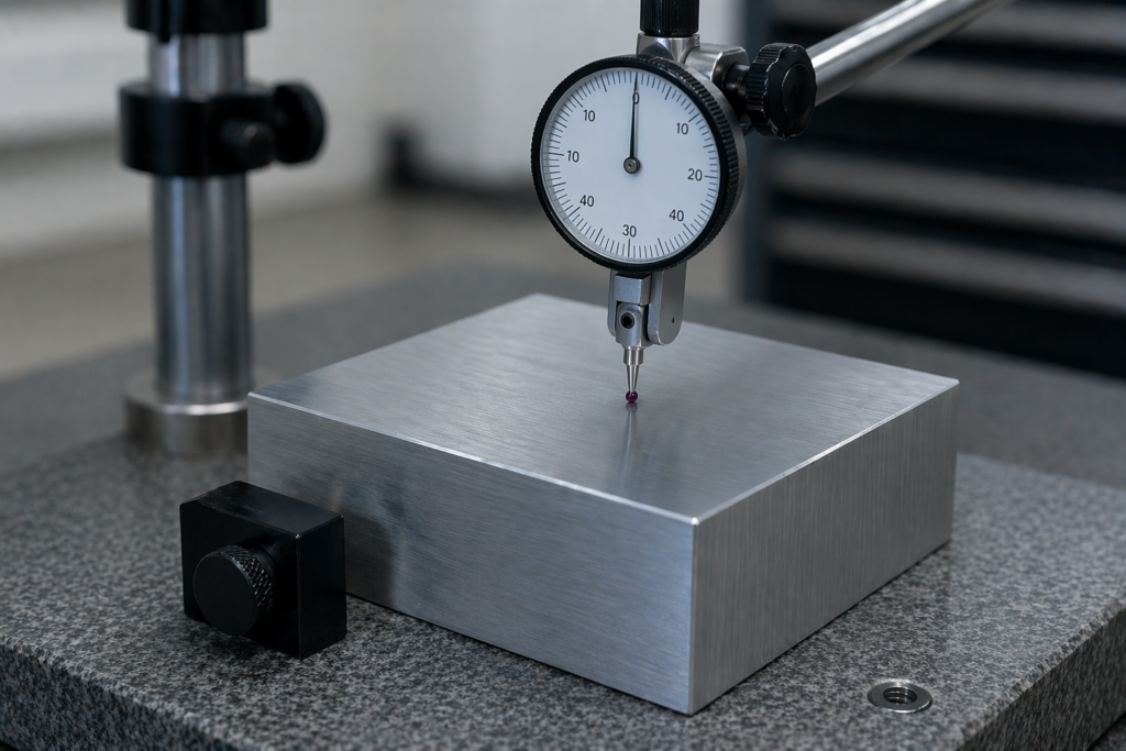
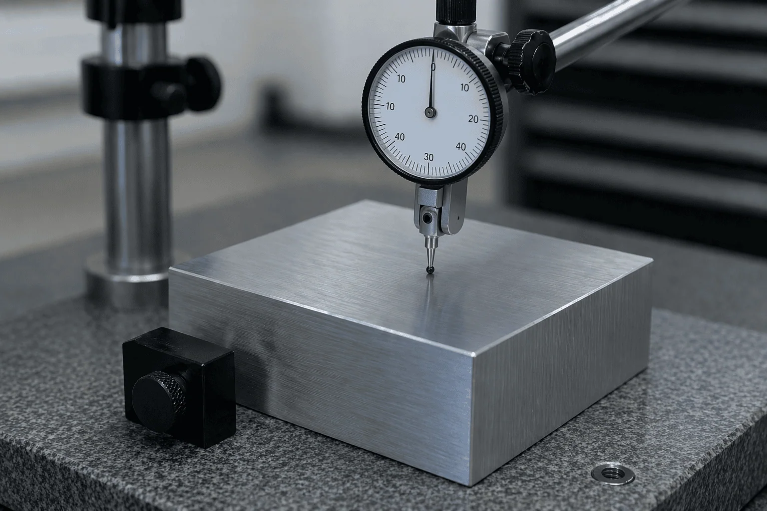
The dial indicator probe contacts the top surface and is traversed across the part. The difference between the highest and lowest recorded readings dictates the parallelism tolerance value. (e.g., A maximum reading of 0.08 mm and a minimum of 0.02 mm results in a parallelism error of 0.06 mm ).
Laser Interferometer and Autocollimator
For parts that are extremely large or cannot be moved, laser interferometers and autocollimators are the go-to inspection solutions.
These tools analyze angular deviations or interference patterns in a reflected beam of light to achieve sub-micron accuracy. However, they are highly sensitive to environmental factors like thermal expansion, humidity, and air turbulence.
Mastering Orientation Controls
Parallelism is a fundamental GD&T orientation tolerance critical for the reliable production of parallel surfaces. By maintaining uniform spacing and alignment within the required limits and fits, it ensures proper assembly, leak-proof sealing, and long-term mechanical reliability.
By understanding its specific tolerance zones and material conditions, engineers can apply parallelism effectively without unnecessarily inflating manufacturing costs.


Comment(0)