

 Europe
  Türkiye
  United Kingdom
  Global





 Login with my Xometry account


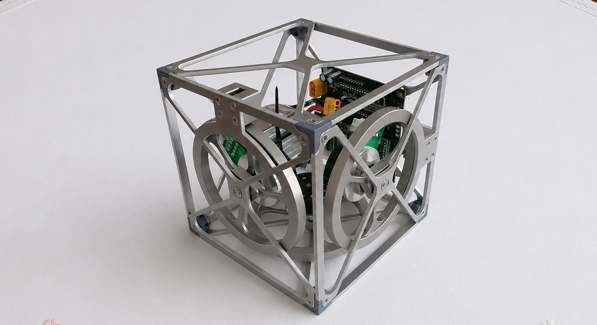
Hi, I’m Timon Moser, and together with Alexander Moldaschl and Florian Fafilek from the Mechanical Design and Construction Department at HTL Hollabrunn, Austria, we developed a self-balancing gyroscopic cube as part of our diploma thesis.
The Idea: A Cube That Does Not Simply Fall Over
The project did not begin with a typical everyday problem, but with a technical challenge: Can a cube be stabilized using internal reaction wheels? The idea eventually evolved into a fully functional Cubli: a compact system that combines mechanical design, electronics, and control engineering.
A Cubli is a gyroscopic cube that can balance on an edge or corner using rotating flywheels. A sensor detects the cube’s position, a microcontroller processes the data, and controls the motors. By changing the flywheels’ rotational speed, reaction torques are generated that help restore the cube’s balance.
For the team, the project was especially exciting because it combined several disciplines: mechanics, electronics, software, and control engineering. I was particularly interested in working on a project that was not only theoretical, but could actually be built and made to work.
From a 2D Test Setup to a 3D Cubli
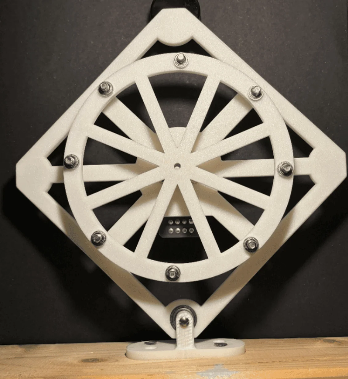
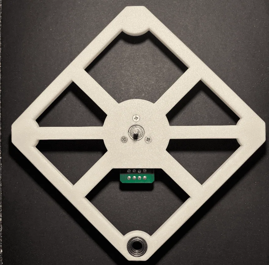
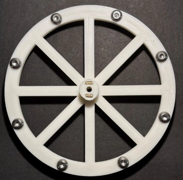
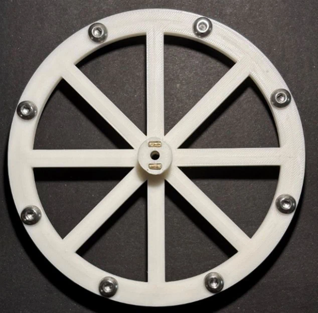
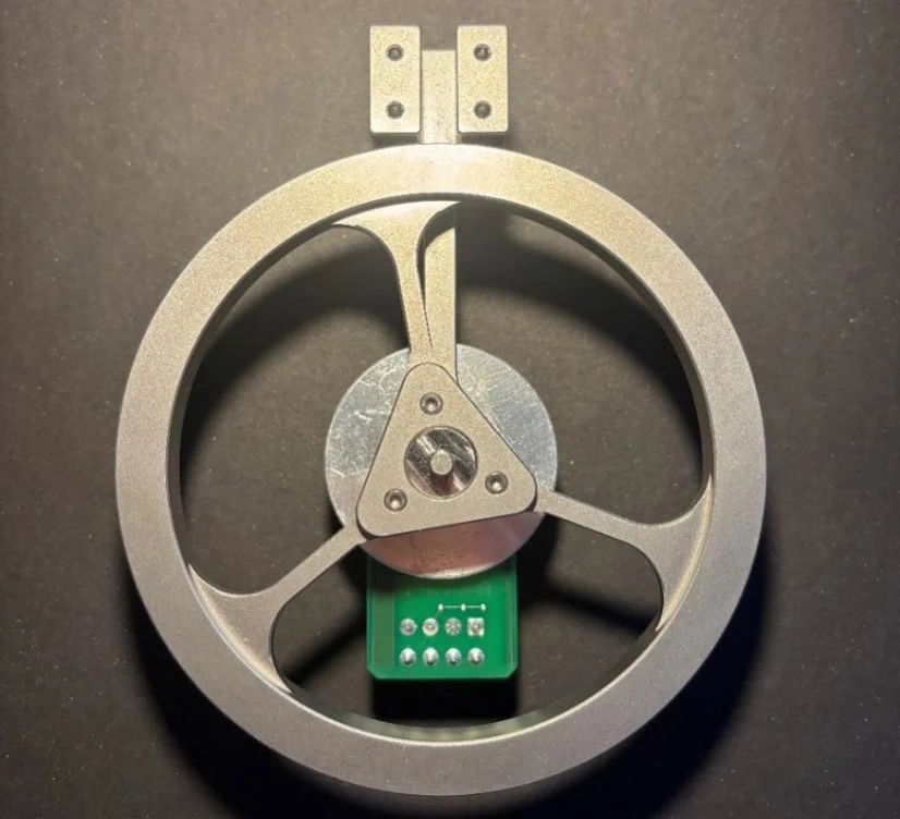
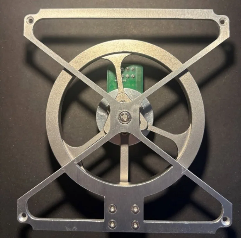
Before building the complete 3D cube, our team first developed a two-dimensional test setup. This reduced the complexity to a single tilting axis and made the basic principle easier to control: one frame, one motor, one reaction wheel, and one defined axis of rotation.
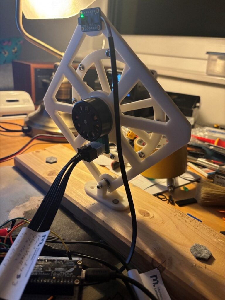
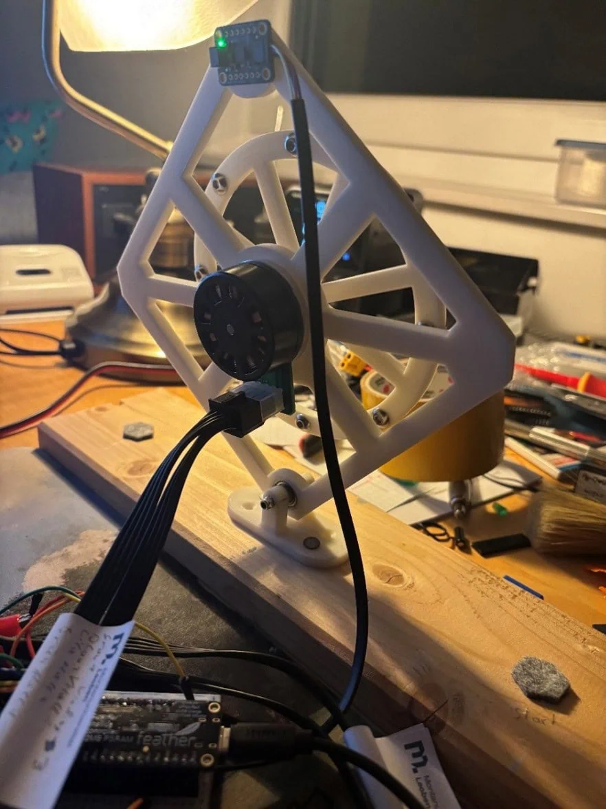
This intermediate step was crucial. The 2D setup helped to understand the behavior of a single reaction wheel, observe the mass distribution, and identify potential design issues at an early stage. Only then was the principle transferred to three spatial axes.
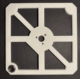
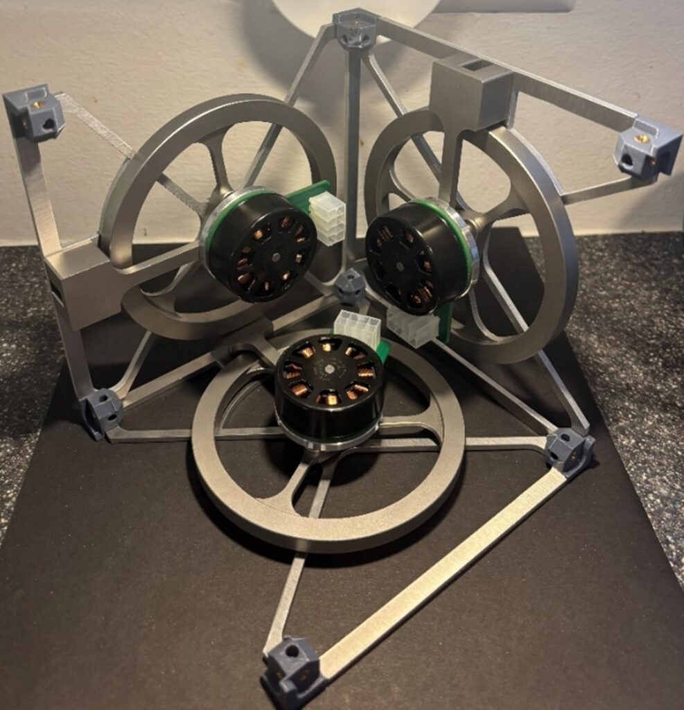
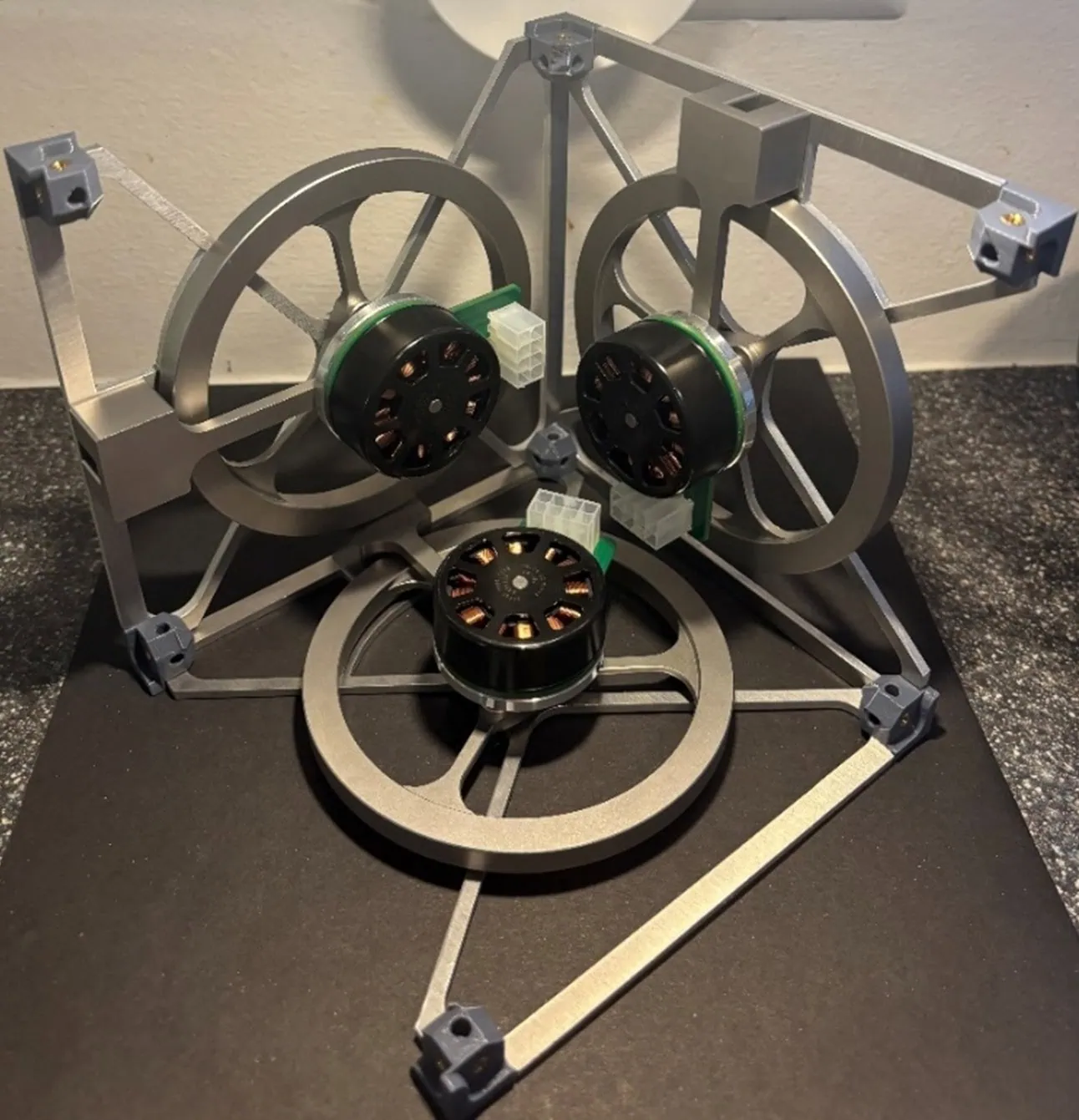
The final 3D Cubli consists of six rectangular frame parts that form the cube. Inside are three orthogonally arranged reaction wheels, motors, motor mounts, torque transmission components, and the electronics, including the PCB. Each axis must be able to act independently without colliding with the other wheels or components.
Design: When the Center of Gravity Determines Functionality
In a project like this, success does not depend only on whether all parts fit together. What matters just as much is where the mass is located.
When balancing, the Cubli is in an unstable equilibrium position. Even small deviations in the center of gravity can create additional tipping moments and make control more difficult. That is why the heavy components had to be positioned as close to the center as possible. At the same time, the cube needed sufficient space for motors, reaction wheels, bearings, torque-transmission components, and electronics.
I was mainly responsible for the mechanical part of the project. Alexander handled the software and PCB design, while Florian handled the electronics, calculations, wiring, and assembly. This clear distribution of responsibilities was important because mechanics, electronics, and control engineering directly interact in this project.
The most important mechanical components included:
- Frame parts as the supporting structure
- Reaction wheels to generate angular momentum
- Motor mounts
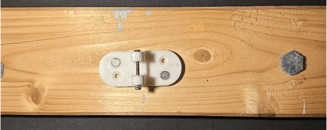
- Torque transmission components
- Bearings and connecting elements
- 3D-printed corner elements
- PCB and electronic components
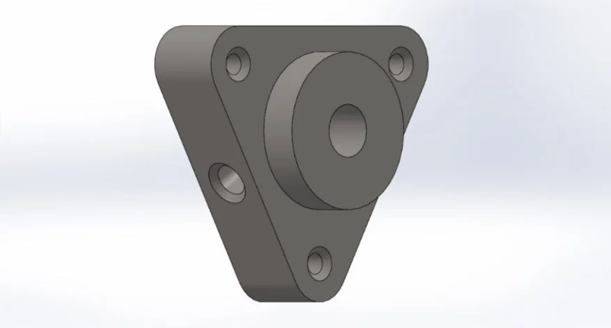
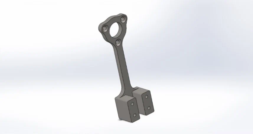
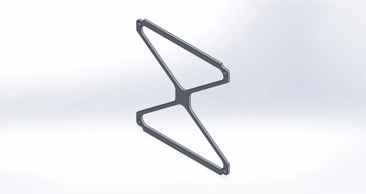
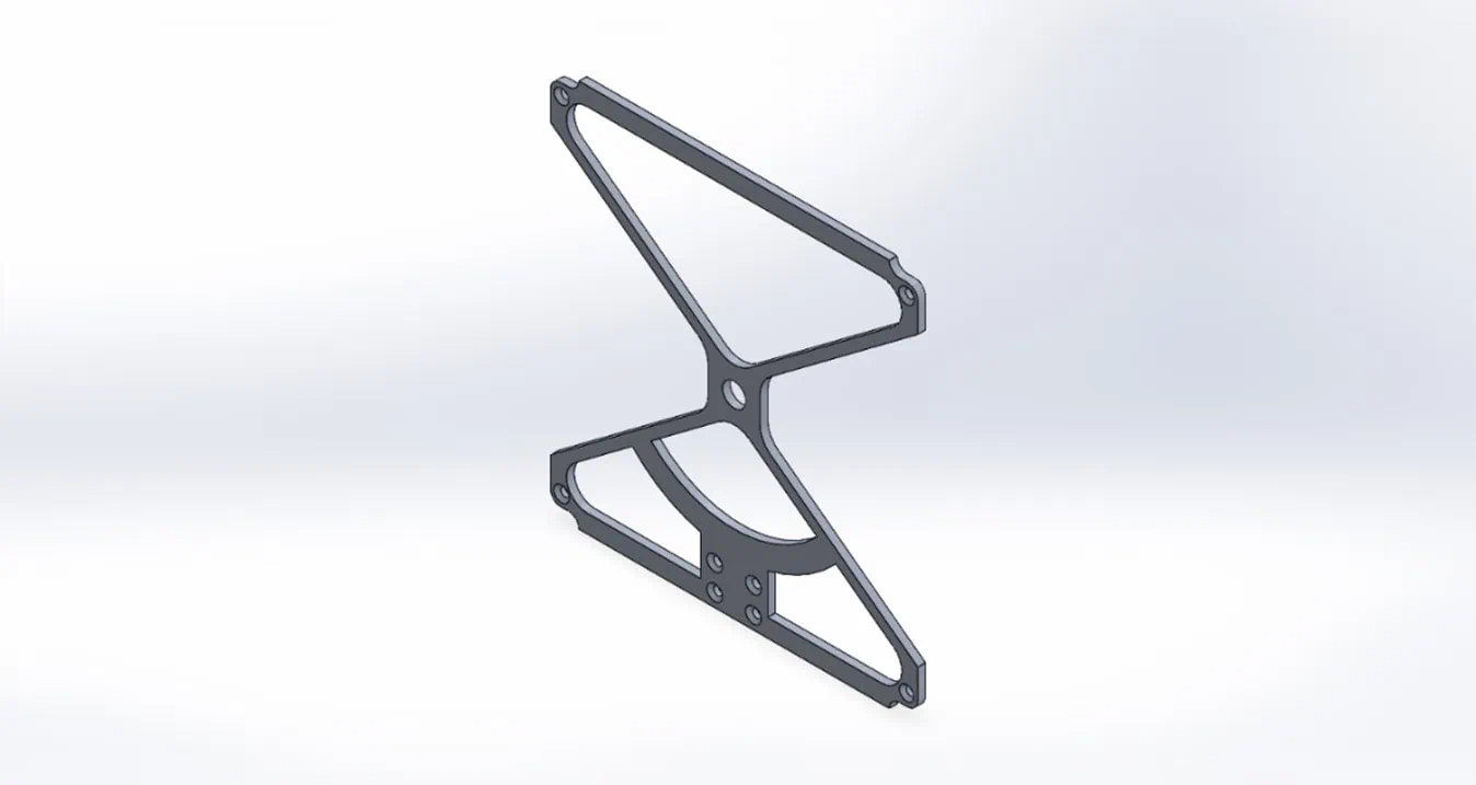
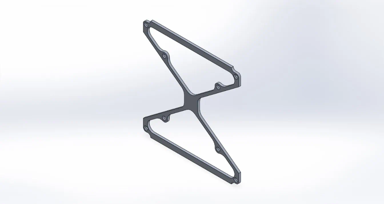
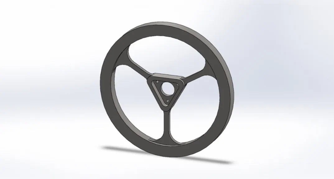
The biggest challenge was coordinating all mechanical components in such a way that the setup would actually work later and fit together precisely.
Laser-Cut Frame Parts as a Stable Foundation
For the frame parts we chose laser cutting. These components form the basic structure of the cube and had to be lightweight, stable, and precisely manufactured. Aluminum was the obvious choice because it offers a good combination of low weight and sufficient stability.
The laser-cut frame parts were manufactured with support by Xometry. For our team, not only was the manufacturing itself important, but also the fast and straightforward process. In a diploma thesis, time is limited. Quotes, decisions, and manufacturing steps, therefore, need to fit together quickly.
For our team, this was practical help and proof that companies take technical student projects seriously. In a project with a limited budget and tight schedule, a reliable manufacturing partner can make a decisive difference. Beyond a clean finish, the frame parts had to ensure precise mechanical assembly.
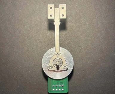
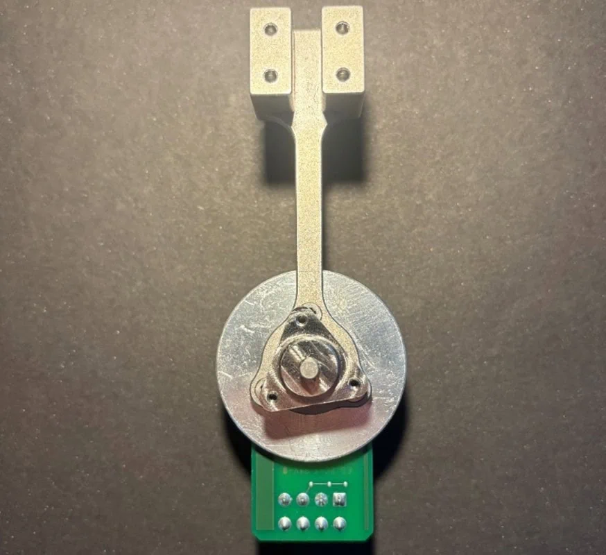
Challenges: Small Manufacturing Details with Major Consequences
As with many technical projects, the gyroscopic cube also showed that the most important lessons often do not appear in the CAD model, but during real assembly.
One particular challenge was cutting threads in stainless steel components. The thread taps broke off and got stuck in the motor mount and torque transmission parts. As a result, some threads could not be completed initially. The problem was not only frustrating but also blocked further mechanical assembly.
We looked for external solutions and learned how important design for manufacturability really is. Some holes could have been adjusted earlier, certain thread depths proved unfavorable for manual machining, and small details had a greater impact than expected.
This became one of the project’s most important lessons: even small design decisions can later have major consequences for manufacturing, assembly, and functionality.
Where the Project Leads Next
In the end, the result is not only a technical demonstrator but a project that closely connects theory and practice. The team built a functional 2D test setup, completed the final mechanical and electrical assembly of the 3D Cubli, and gained valuable experience in design, manufacturing, electronics, and project work.
For me it was especially motivating to see an idea gradually turn into a physical system. What excites me most is that, in the end, you have a real functioning system in front of you and not just a theoretical concept.
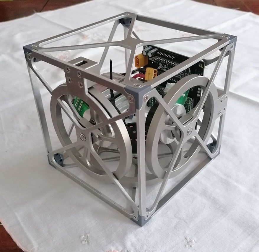
The next steps are the full implementation and testing of the stabilization system. One possible future development would be enabling the Cubli to stand itself up autonomously.
The most important insight, however, is already clear: technical projects rarely work without detours. And that is exactly what makes them valuable. Planning, precision, and clean design are important – but so is the ability to react flexibly to problems and keep going.
Share Your Engineering or Product Design Story

Share Your Story!
Share your engineering and product design journey and get a €300 reward! Showcase your innovative solutions and best practices with our community.
Share Your Engineering or Product Design Story
- We’re looking for stories about innovative mechanical engineering solutions, the design and development of mechanical components, or the creation of cutting-edge hardware products.
- Our team will assist you in preparing your story and translating it into several languages.
- Plus, you’ll receive a reward of 150 EUR to be redeemed with Xometry after your story is published*.
Related Topics
 Javier López Picazo
 2
4
2
4




Comment(0)