

 Europe
  Türkiye
  United Kingdom
  Global






 Login with my Xometry account




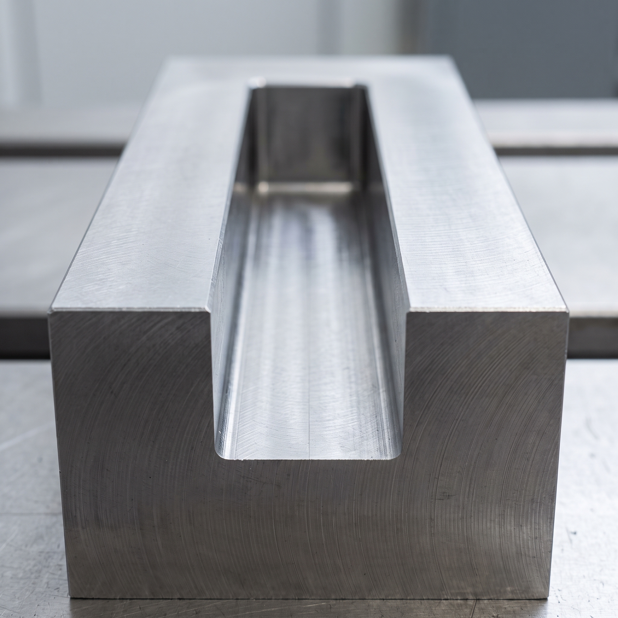
As per ASME Y14.5-2018, GD&T consists of twelve tolerances categorized into five groups based on the feature aspect under control: form, orientation, location, profile, and runout.
Perpendicularity, along with parallelism and angularity, forms the orientation control group, where tolerances control the angular relationship between features.
What Is Perpendicularity in GD&T?
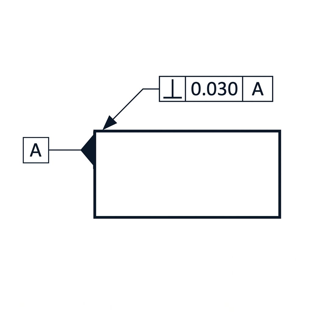
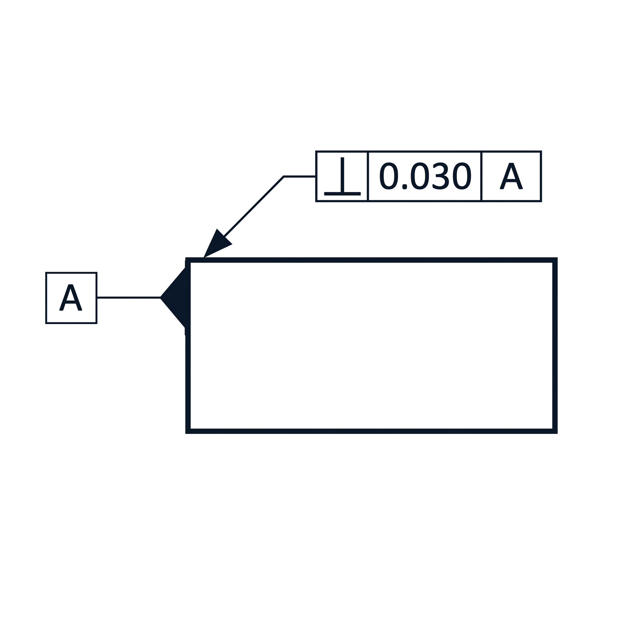
Perpendicularity is an orientation control that maintains a surface, a feature’s axis, or a feature’s center plane at a right angle to a datum plane or datum axis. Depending on the feature being controlled, perpendicularity falls into three types: surface perpendicularity, axis perpendicularity, and center plane perpendicularity.
Surface perpendicularity maintains a surface perpendicular to another surface or axis, assuring a precise 90-degree alignment for mating surfaces, feature sides, or structural supports. Axis perpendicularity applies to features of size, such as holes or pins, and maintains their axis perpendicular to a datum surface or datum axis. Center plane perpendicularity maintains the median plane of a feature of size, the mid-plane equidistant between two opposing surfaces, perpendicular to a datum surface or axis. This ensures the center orientation of features like slots and tabs stays square to the reference surface, rather than only controlling surface flatness.
Perpendicularity Tolerance Zone
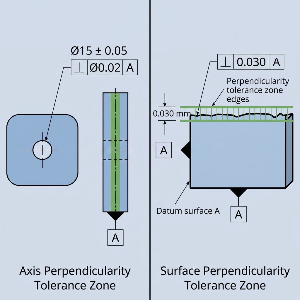
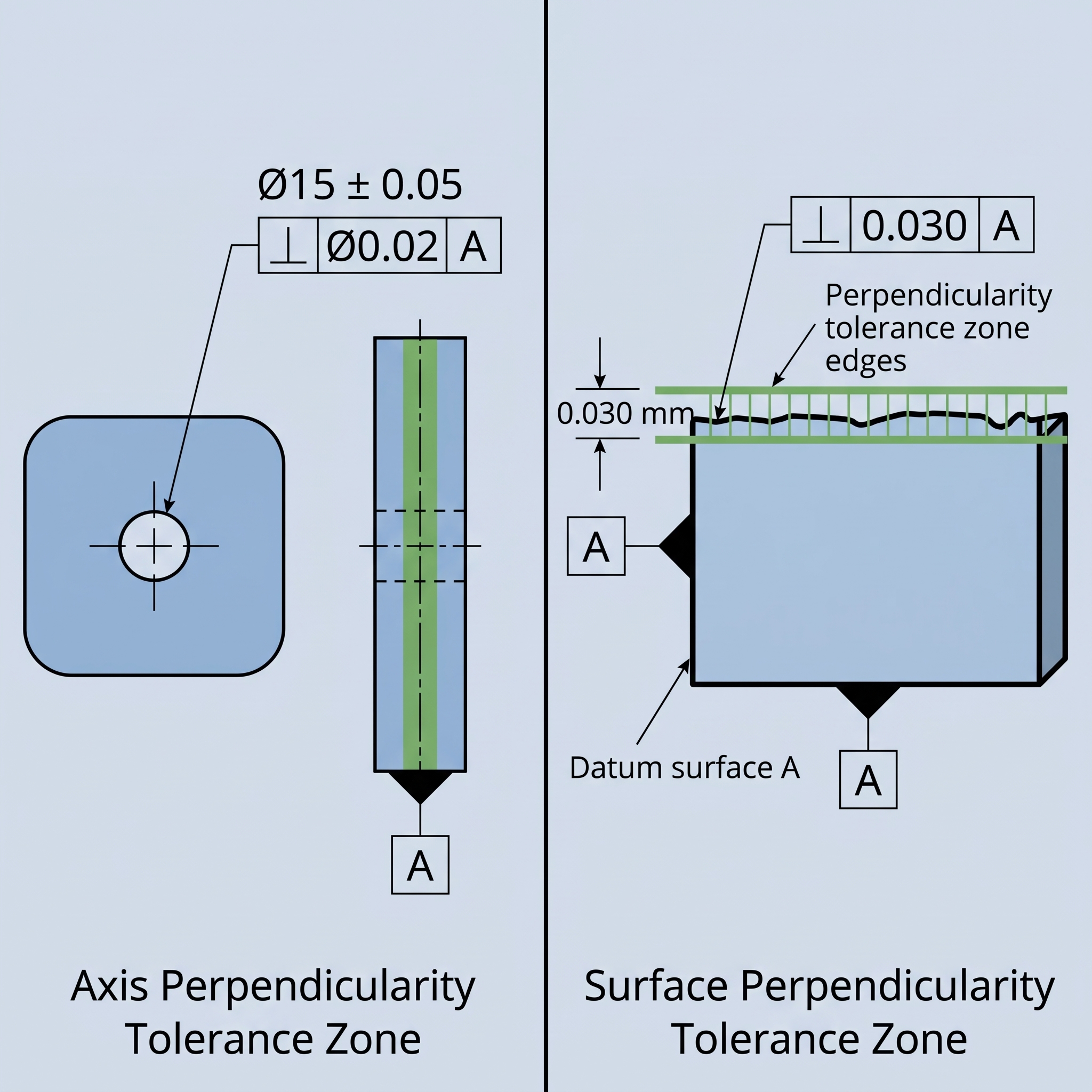
The perpendicularity tolerance zone is a boundary that limits the allowable variation in a feature’s dimensions. For a part to be in spec, every point on the feature axis (for axis perpendicularity), the controlled surface (for surface perpendicularity), or the median plane (for center plane perpendicularity) must lie within the defined tolerance zone.
Two tolerance zone shapes apply to perpendicularity. The default zone, made of two parallel planes, is used for both surface perpendicularity and center plane perpendicularity. This zone sits at the surface for surface perpendicularity, and at the feature’s median plane for center plane perpendicularity. The distance between the two planes is the allowable tolerance limit. If a surface’s perpendicularity tolerance is set at 0.1 mm, every point on that surface must lie within two parallel planes spaced 0.1 mm apart.
The second zone type is cylindrical, used for axis perpendicularity. This zone applies to features of size, such as holes and pins, and is placed at the ideal axis of the feature. The diameter of the tolerance zone cylinder is the allowable tolerance limit. If an axis’s perpendicularity tolerance is set at 0.1 mm, every point on the actual axis must lie within a cylindrical zone 0.1 mm in diameter, centered on the ideal axis.
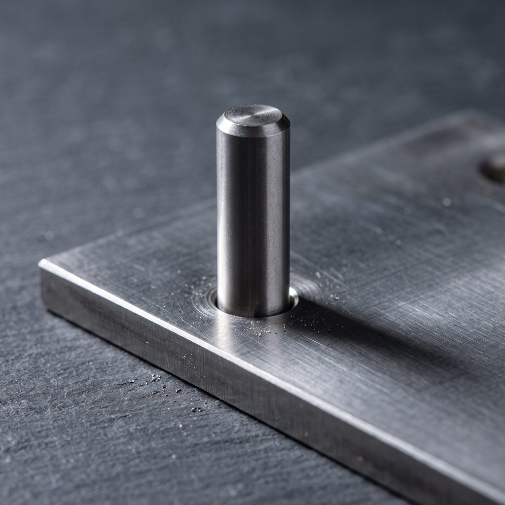
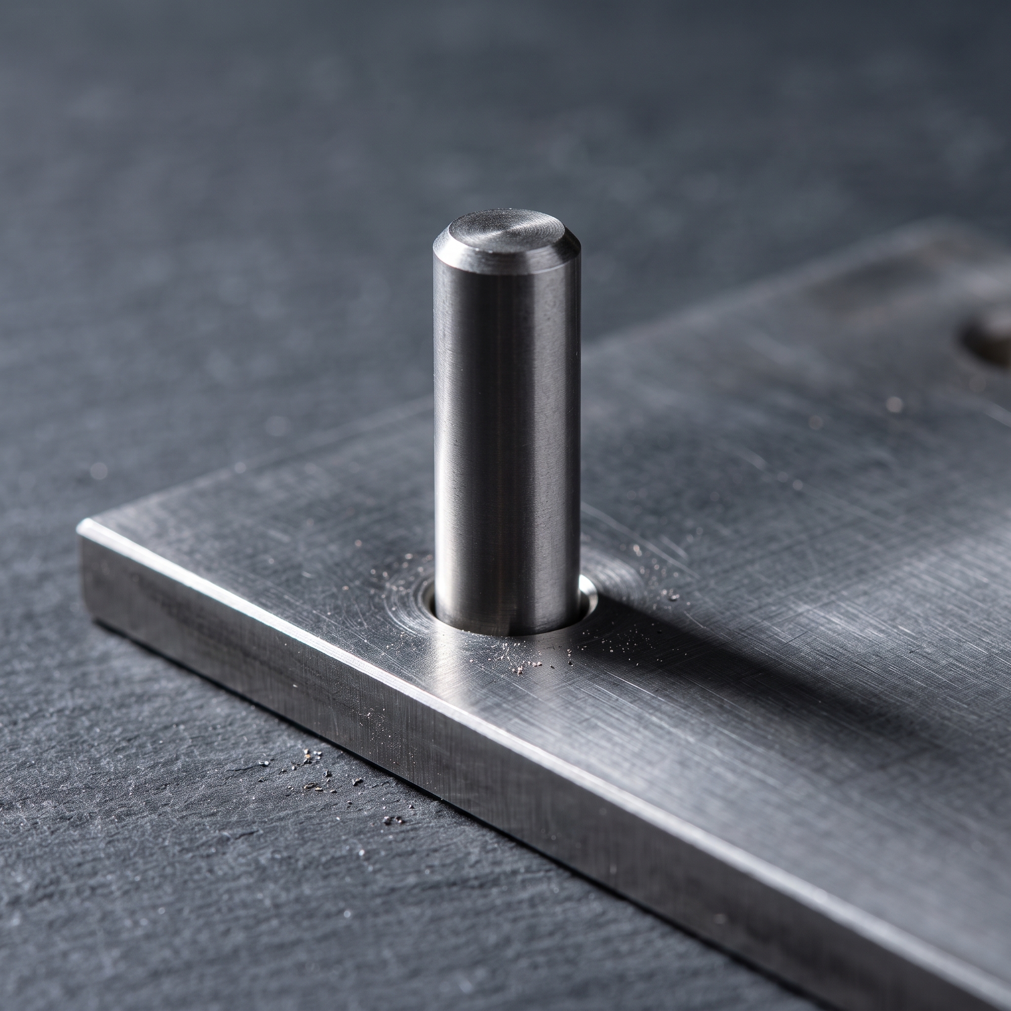
Projected tolerance zone for threaded and press-fit holes
For perpendicularity on threaded or press-fit holes, the tolerance zone is sometimes projected above the part to control how the mating stud or pin will tilt once installed. This is shown with the Ⓟ modifier and a projection height. A callout reading ⟂ 0.1 Ⓟ 25 means the axis must stay within a 0.1 mm cylindrical zone extending 25 mm above the hole, not inside the hole itself. Without this modifier, a hole can pass inspection but still cause assembly interference once the mating fastener is installed.
Perpendicularity Feature Control Frame
The perpendicularity tolerance is applied to a feature on an engineering drawing using a feature control frame. The frame provides all the information needed to manufacture and inspect a part correctly, consisting of a geometric characteristic symbol, the tolerance zone shape, the tolerance value, modifiers, and datum feature reference letters where applicable.
For surface perpendicularity, the feature control frame connects to the feature through a leader arrow pointing directly at it, or through an extension line for planar surfaces. Since axis and center plane perpendicularity apply to features of size, the frame connects through an extension of the dimension line and may sit adjacent to the size dimension.
A general feature control frame divides into three blocks: the GD&T symbol block, the tolerance block, and the datum block.
GD&T symbol block
The first block holds the symbol for the applied tolerance. The symbol for perpendicularity is a vertical line resting on a horizontal line (⟂), representing a 90-degree angle.
Tolerance block
The tolerance block defines the tolerance zone shape, the tolerance value, and any modifiers. For axis perpendicularity, a diameter symbol precedes the tolerance value to indicate a cylindrical zone. For surface and center plane perpendicularity, no zone shape symbol is needed, since the default parallel-plane zone applies.
The tolerance value follows the zone shape. For surface and center plane perpendicularity, this value is the distance between the parallel planes. For axis perpendicularity, this value is the diameter of the cylindrical zone.
Material condition modifiers may follow the tolerance value when the tolerance applies to a feature of size such as a hole or pin. Maximum material condition (MMC) and least material condition (LMC) are denoted by a circled M or L. When a tolerance is applied at MMC, the feature must have perfect form at that size. As the feature departs from MMC, the perpendicularity tolerance can loosen while still meeting assembly and functional requirements. This extra tolerance is bonus tolerance, covered in detail below.
When no modifier appears in the tolerance block, the tolerance applies regardless of feature size (RFS). In this case, the tolerance must be strictly met, with no provision for bonus tolerance.
Datum block
Perpendicularity creates a perpendicular feature, but a feature cannot be perpendicular without a reference. That reference is a datum feature, which could be an alternate surface, axis, or edge of the part.
Datum features are mandatory for orientation controls and are listed in the datum block in decreasing order of importance: primary, secondary, and tertiary. A stable, flat, and easily accessible surface is generally chosen as the primary datum, with the largest mating surface typically the best option since it ensures correct assembly. Secondary and tertiary datums refine the tolerance further where needed.
Perpendicularity is typically defined with one to two datums, depending on the part’s complexity. A third datum may be added if location, not just orientation, also needs to be controlled.
Bonus Tolerance in Perpendicularity
One of the goals of GD&T is proper assembly, which means defining the worst-case scenarios that still allow correct assembly. A feature of size, external or internal, is regularly qualified using material modifiers that limit its maximum or minimum size, ensuring the part is never manufactured beyond that limit.
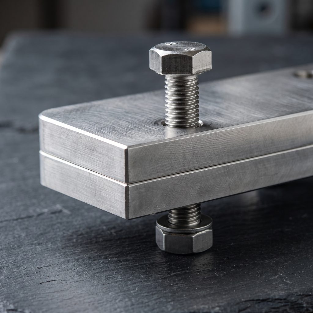
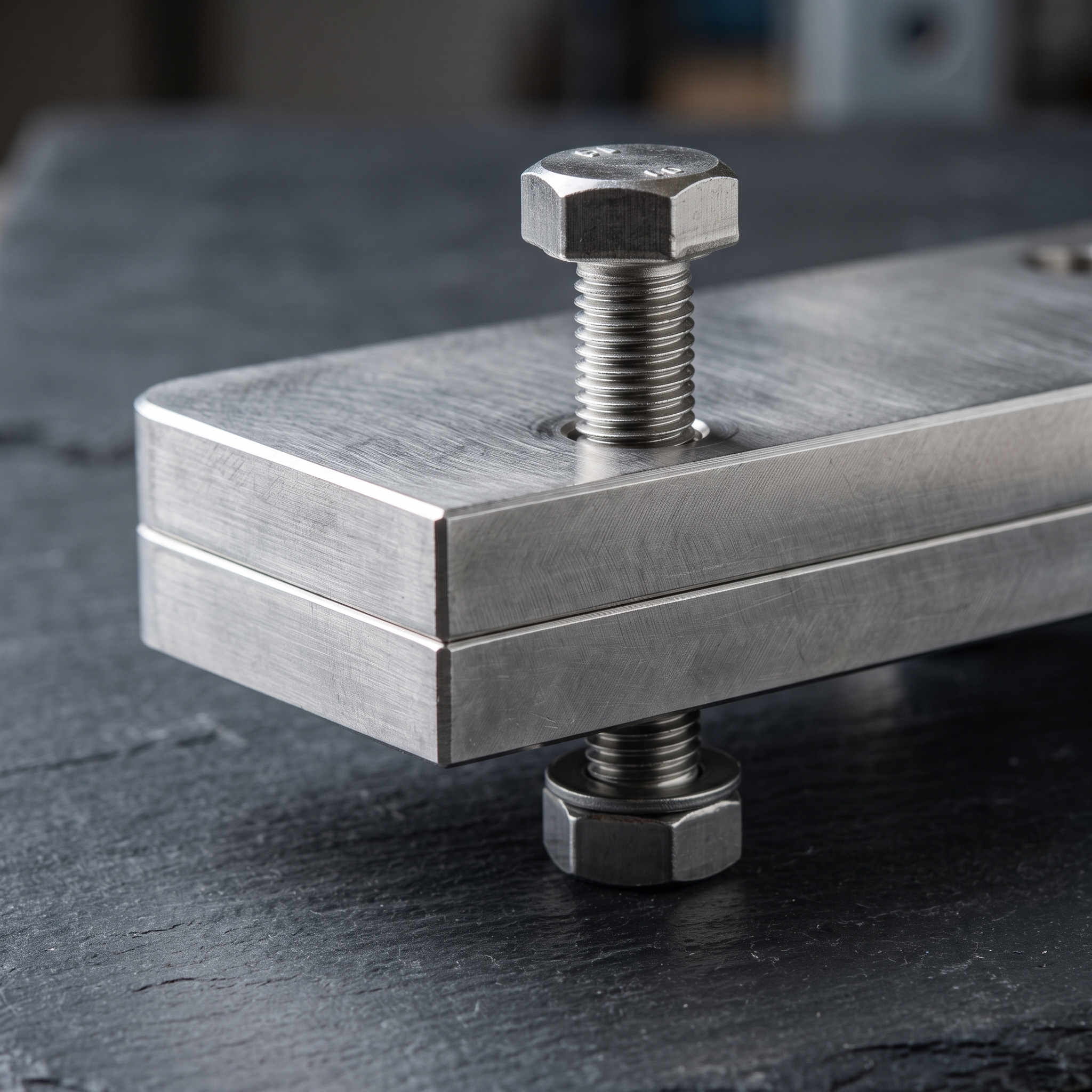
Consider a pin on a flat surface that must assemble into a hole on another part. Defining the perpendicularity tolerance with a material condition modifier restricts that tolerance to the stated limit only when the part is at its maximum size. If the pin is manufactured smaller than that maximum, a greater margin of error in perpendicularity becomes acceptable without compromising assembly.
This works like packing a suitcase. A full suitcase leaves no room to rearrange the contents, but a partly filled one allows items to shift while everything still fits. Bonus tolerance is that empty space: the difference between a feature’s stated MMC or LMC size and its actual manufactured size.
Bonus Tolerance Calculation
| Feature Type | Bonus Tolerance Formula | Example |
| Internal feature (hole) | Actual Size − MMC Size | MMC 10.00 mm, actual 10.10 mm → 0.10 mm bonus |
| External feature (pin or shaft) | MMC Size − Actual Size | MMC 10.00 mm, actual 9.90 mm → 0.10 mm bonus |
Internal features gain bonus tolerance as size increases, while external features gain bonus tolerance as size decreases. The total allowable perpendicularity tolerance becomes the sum of the stated tolerance and the bonus tolerance.
In some cases, a feature is specified without a material condition modifier, particularly for parts that rotate at high speed or serve high-precision applications. The tolerance is then applied regardless of feature size (RFS): the stated perpendicularity tolerance is fixed and indifferent to the part’s actual size, with no bonus tolerance available.
Perpendicularity vs. Other Callouts
Perpendicularity can appear to control aspects similar to flatness and angularity. Understanding the difference between these tolerances ensures each is applied correctly.
Table 2: Perpendicularity vs. Related GD&T Callouts
| Callout | Category | Requires a Datum | Controls Angle to Datum | Tolerance Zone |
| Perpendicularity | Orientation | Yes | Fixed at 90 degrees | Parallel planes or cylinder |
| Flatness | Form | No | Not applicable | Parallel planes |
| Angularity | Orientation | Yes | Any basic angle other than 0 or 90 degrees | Parallel planes or cylinder |
Perpendicularity vs. flatness
Perpendicularity and flatness are similar in some ways, both applicable to planar surfaces and both using a parallel-plane tolerance zone. Fundamentally, though, they differ. Flatness is a form control, simpler than orientation controls like perpendicularity, since form controls care only about a feature’s shape, not its location or orientation. When applied to a surface, flatness compares the actual surface with its perfect version: as long as the distance between the surface’s high and low points is less than the tolerance zone, the part passes.
Perpendicularity adds orientation control on top of that. It implicitly controls flatness while also controlling the feature’s direction relative to the datum, maintaining a 90-degree alignment. A surface can be extremely flat but leaning at 85 degrees instead of 90, passing flatness while failing perpendicularity.
Perpendicularity vs. angularity
Angularity and perpendicularity are both orientation controls. Angularity creates an angled tolerance zone between the controlled feature and the datum feature, used to align a feature at any angle other than 0 or 90 degrees, including obtuse angles greater than 90 degrees. The angle is specified as a basic dimension, and the tolerance zone is expressed as a linear width, using the same default parallel-plane zone.
Perpendicularity is a special case of angularity, reserved specifically for 90-degree orientation. A surface at 80 degrees to the datum fails perpendicularity but may pass angularity if an 80-degree tolerance is specified instead.
How to Measure Perpendicularity
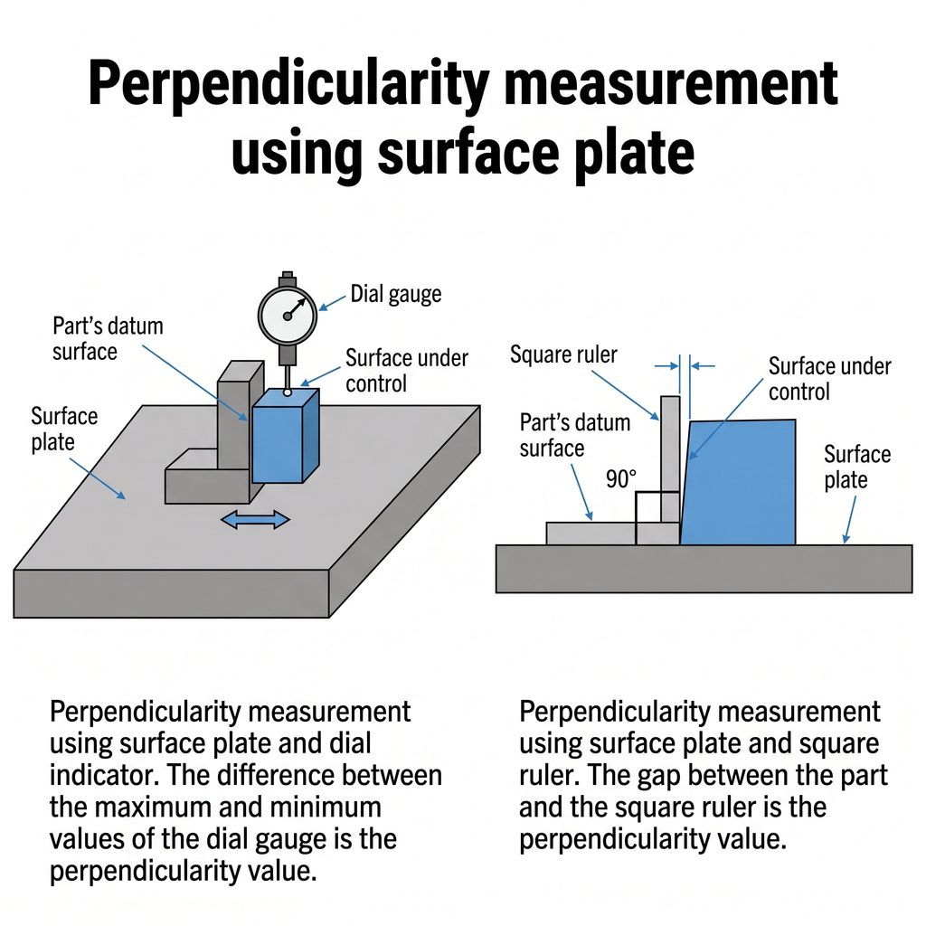
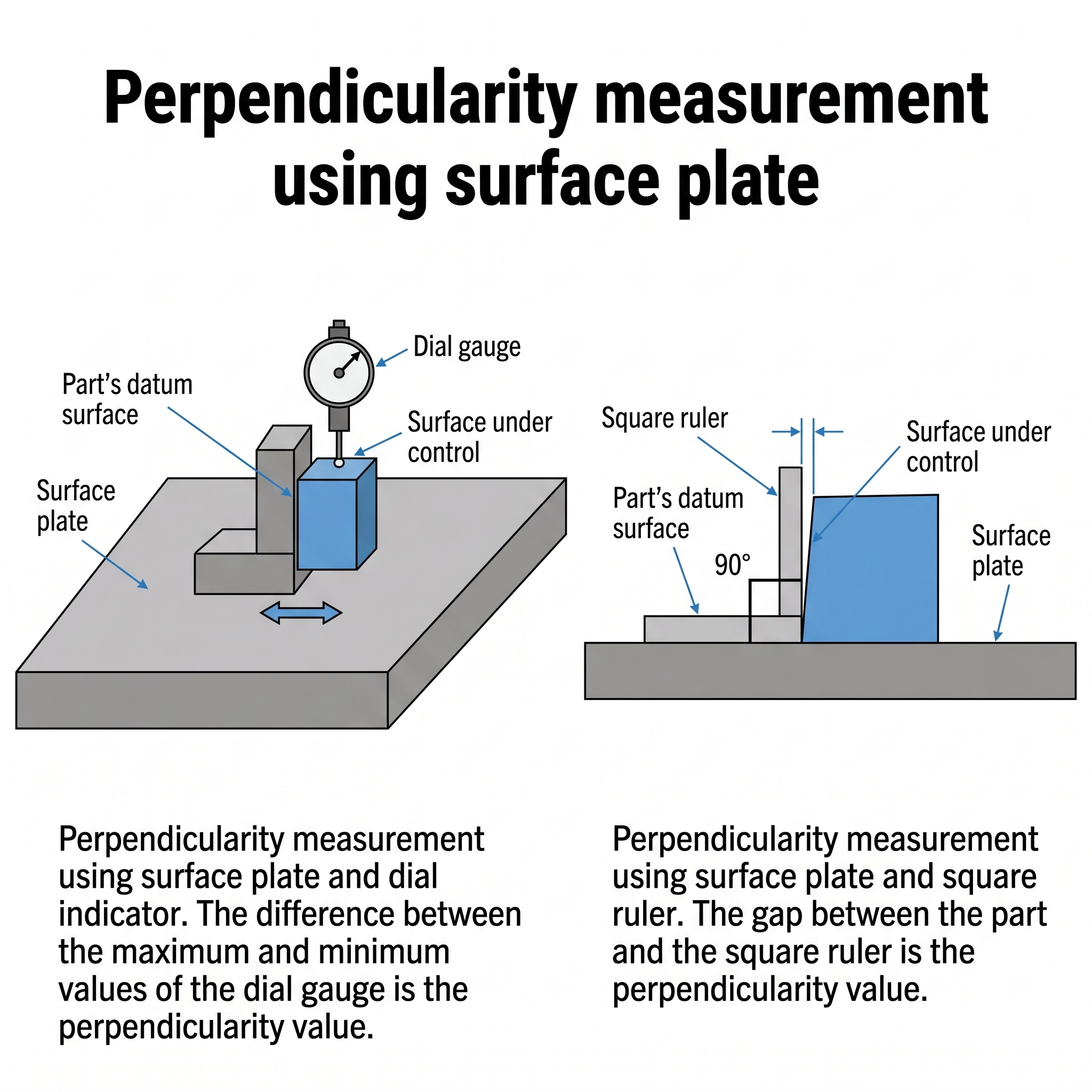
Perpendicularity is always applied with respect to a datum element, so inspection must also be carried out relative to that datum. The right measurement method depends on the accuracy required and the production context: autocollimators, laser interferometers, or coordinate measuring machines suit applications where accuracy is non-negotiable, while surface plates with height gauges, dial indicators, or square rulers suit portable, on-the-go measurement.
Perpendicularity Measurement Method Comparison
| Method | Accuracy | Portability | Best Use Case |
| Surface plate with dial indicator | Moderate | High | Shop floor checks, quick pass or fail decisions |
| Surface plate with square ruler | Moderate | High | Fast visual gap check, low equipment cost |
| Coordinate measuring machine | High | Low | Complex parts, both surface and axis perpendicularity |
| Autocollimator or laser interferometer | Very high | Low | Non-contact measurement on large, delicate, or contamination-sensitive parts |
Surface plate
The surface plate method is a quick, reliable way to measure perpendicularity, paired with a square ruler, dial indicator, or height gauge. In all three approaches, the datum surface rests on a surface plate or other flat reference.

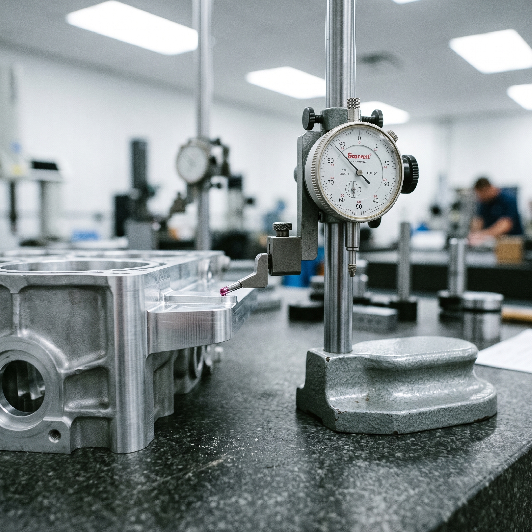
A dial indicator or height gauge probe is then traversed across the controlled surface to capture the maximum and minimum deviation, and the difference between the two is the perpendicularity measurement. With a square ruler, the gap between the ruler and the controlled feature is the measurement itself. As long as this value stays below the stated tolerance, the part passes.
Coordinate measuring machine
A coordinate measuring machine is one of the more reliable methods for measuring perpendicularity, for both surfaces and axes, though it takes more time and costs more than a surface plate check. A probe first collects data points across the datum element to establish it in software, then traverses the controlled surface. The software fits two parallel planes containing the collected points, and the distance between those planes is the perpendicularity measurement. The part passes if this value is lower than the stated tolerance.
Autocollimators and laser interferometers
An autocollimator is a highly sensitive optical instrument for measuring small angles and tilt with remarkable accuracy, suited to parts where very high accuracy is non-negotiable.
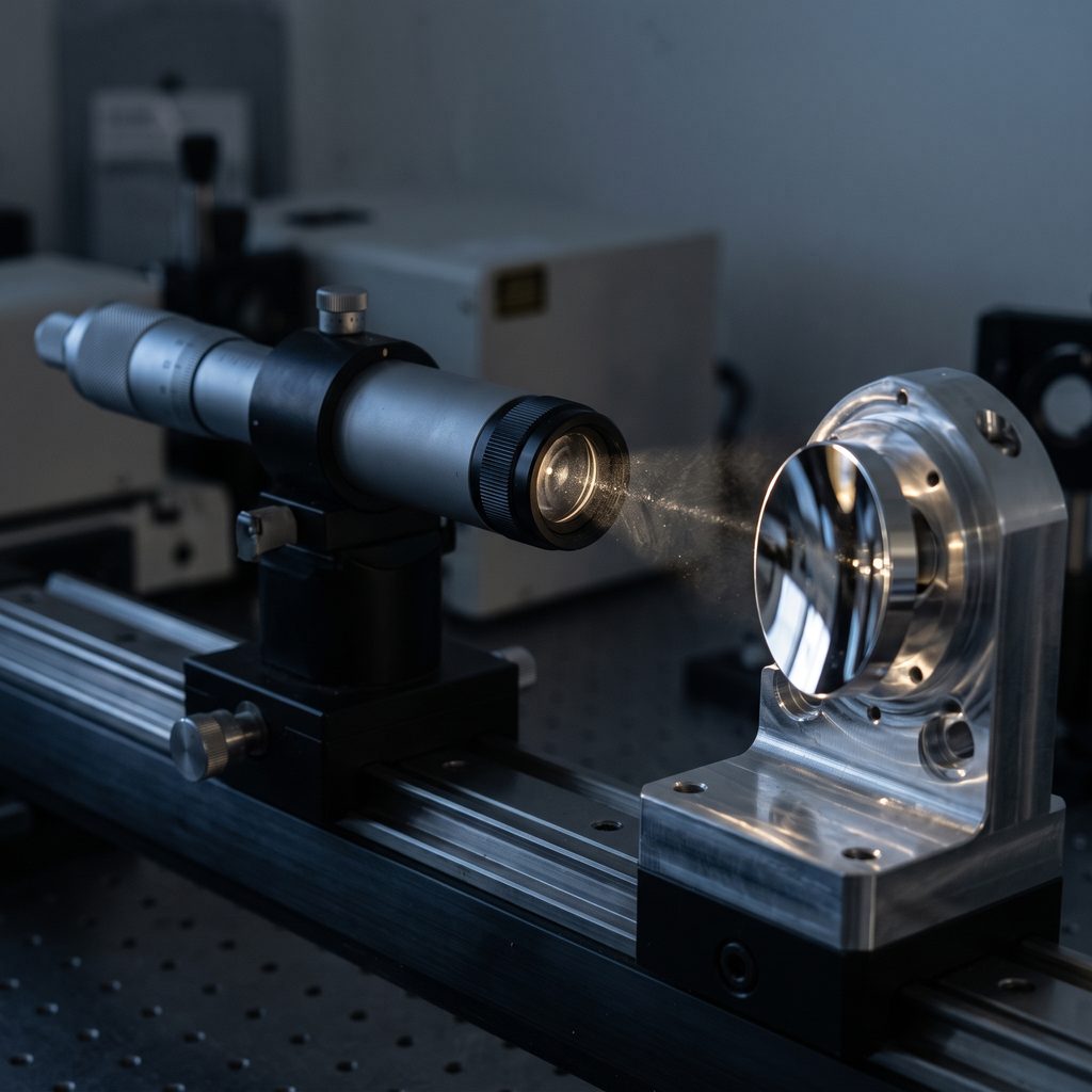
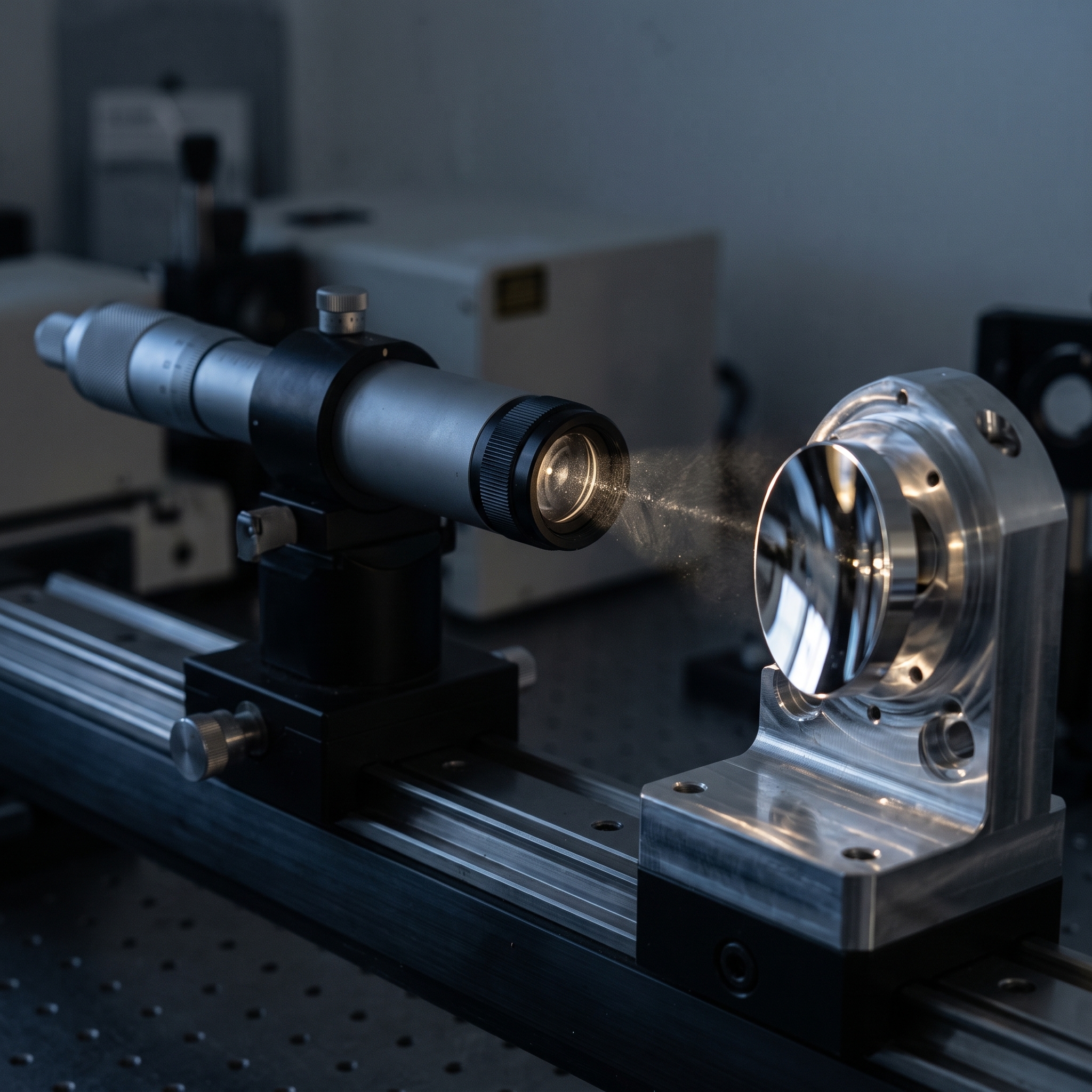
Laser interferometers serve a similar high-accuracy role, measuring path-length differences in reflected laser beams. Both methods are non-contact, making them preferable for large-scale measurements or for parts prone to damage, contamination, or deformation from contact-based inspection.
Conclusion
Perpendicularity is an extensively used tolerance in GD&T, ensuring parts maintain strict 90-degree alignment between surfaces, axes, and median planes relative to a datum. This is fundamental to proper assembly, structural integrity, and long-term reliability.
Understanding when to apply surface, axis, or center plane perpendicularity, and combining it with the correct feature control frame, material modifiers, and datum features, gives manufacturers everything needed to produce and verify a compliant part. Applied correctly, perpendicularity eliminates cost ambiguity, reduces rework, and ensures parts perform as designed throughout their service life. For engineers working across the rest of the orientation and form control family, the GD&T technical library on Xometry Pro also covers flatness, angularity, and concentricity.
Related Topics
 1
1
1
1






Comment(0)