 Europe
  Türkiye


This article provides a comprehensive overview of Cylindricity, a fundamental Form Control that sits alongside Flatness, Straightness, and Circularity. We will cover its definition, tolerance zone, measurement methods, and how it differs from similar callouts.
What is Cylindricity?
Cylindricity is a form control in Geometric Dimensioning & Tolerancing that qualifies a cylindrical part by ensuring the surface’s roundness and the axis’ straightness to meet functional requirements. It does so by defining a tolerance zone around the cylinder’s entire surface.
It also minimizes friction in working mechanisms and extends component life by ensuring consistent alignment.
Being a form control, cylindricity does not need a datum. This means it is not defined with respect to anything external—commonly a fixed point, plane, or axis. It applies strictly to the form of the feature itself. However, a critical rule to remember is that the width of the cylindricity tolerance zone must be less than the size tolerance of the diameter. Failure to ensure this leads to an invalid or redundant callout.
Many applications require a cylindrical part that must fit inside a bore or over a shaft. In such cases, if a part isn’t sufficiently cylindrical, it will not assemble properly.
Example: A cylindrical metal sleeve is often fitted over a pump shaft in corrosive environments to protect it from erosion, corrosion, and abrasion. The sleeve must be sufficiently cylindrical to fit over the shaft without rubbing against it.
This is especially important since the sleeve may be made from a higher-grade material than the shaft. Thus, proper fitting between the shaft and the sleeve is paramount to protect the shaft. Incorrect assembly would not only defeat its purpose but actually do more harm. The clearance between the shaft and the sleeve is often minuscule to ensure a leak-proof fit. If the sleeve isn’t straight enough or cylindrical enough, it will not function as designed.
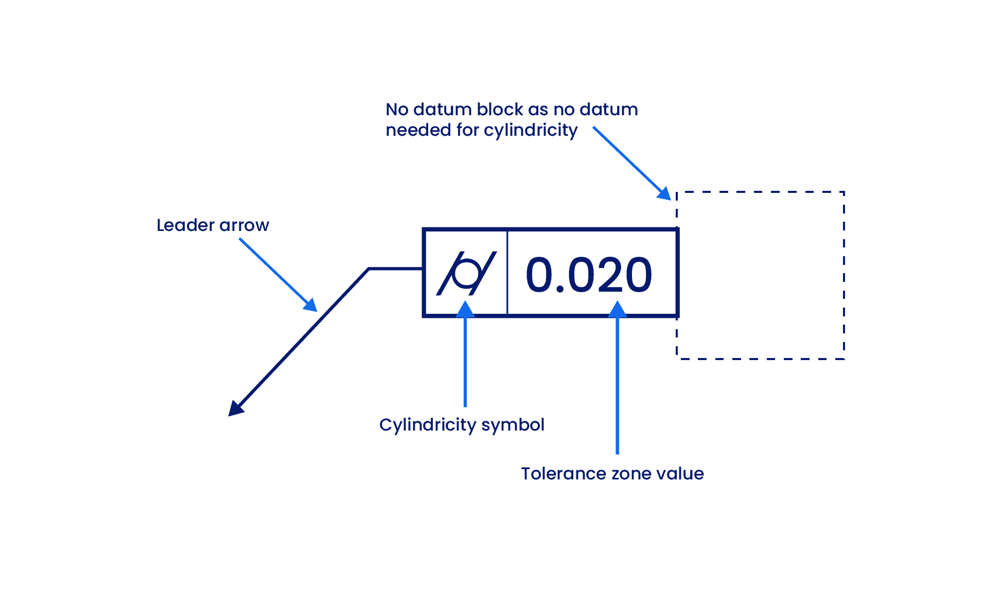
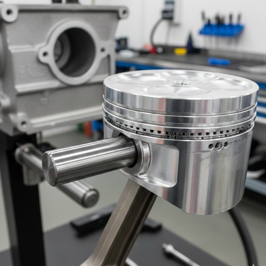
Cylindricity is used in various applications across multiple sectors, including industry and automotive, for components such as hydraulic cylinders, engine crankshafts, long studs, pipelines, and vehicle axles.
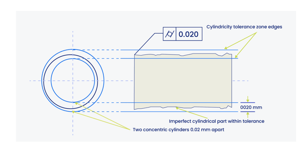
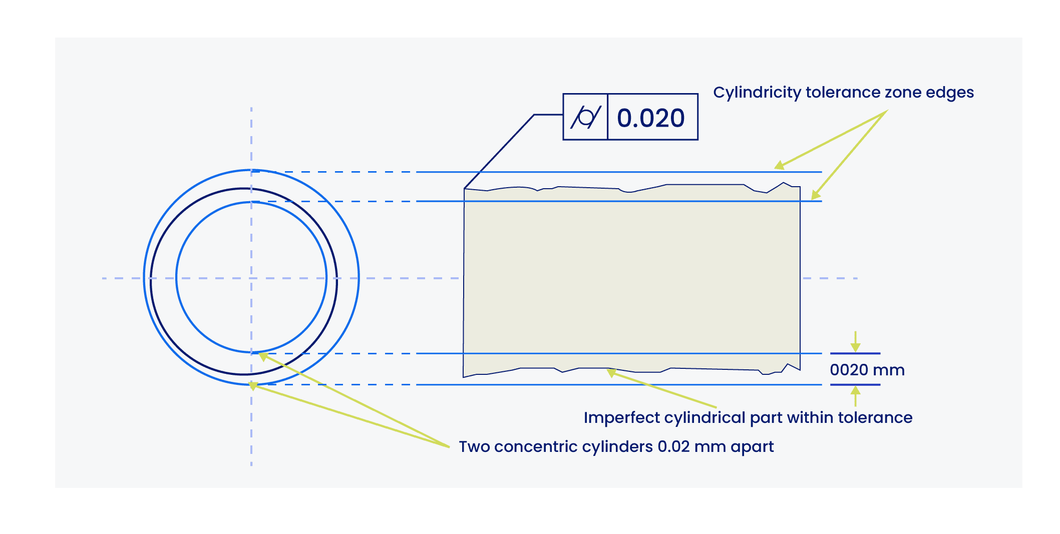
Cylindricity Tolerance Zone
The cylindricity tolerance zone is defined by the volume between two coaxial cylinders (one inside the other). To pass inspection, every point on the part’s surface must lie within the gap between these two virtual cylinders.
The tolerance value is the radial distance between these two cylinders, not the range of diameters.
Think of a cylinder as a stack of coins. By defining a cylindrical tolerance zone, the control ensures two things:
- Each individual coin is perfectly round (Circularity).
- The entire stack forms a straight line without leaning (Straightness).
If even one coin is oval, or if one coin sticks out of the stack due to misalignment, the part fails. The only way to satisfy the control is by being round enough at each cross-section and straight enough along the entire axis.
It is crucial to stress that the tolerance value for cylindricity must be strictly less than the diametral tolerance zone (size tolerance). An invalid callout results if this requirement is not met.
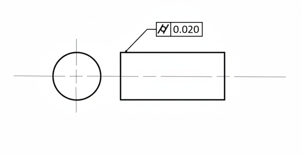
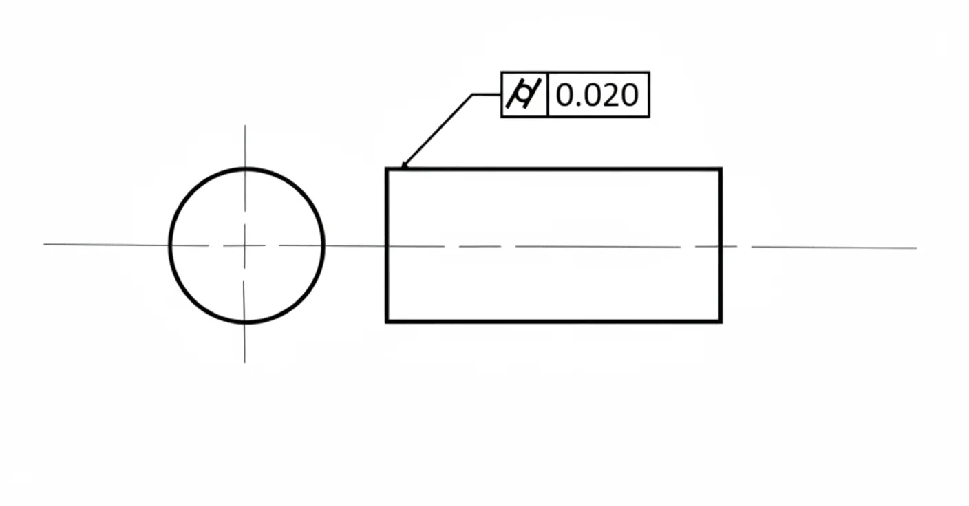
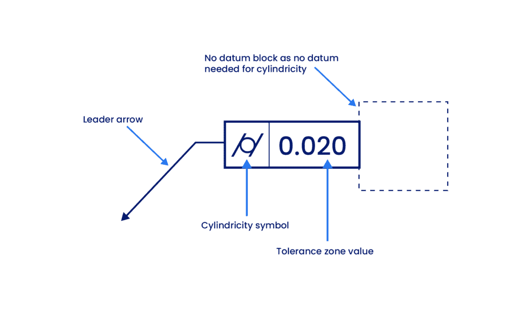
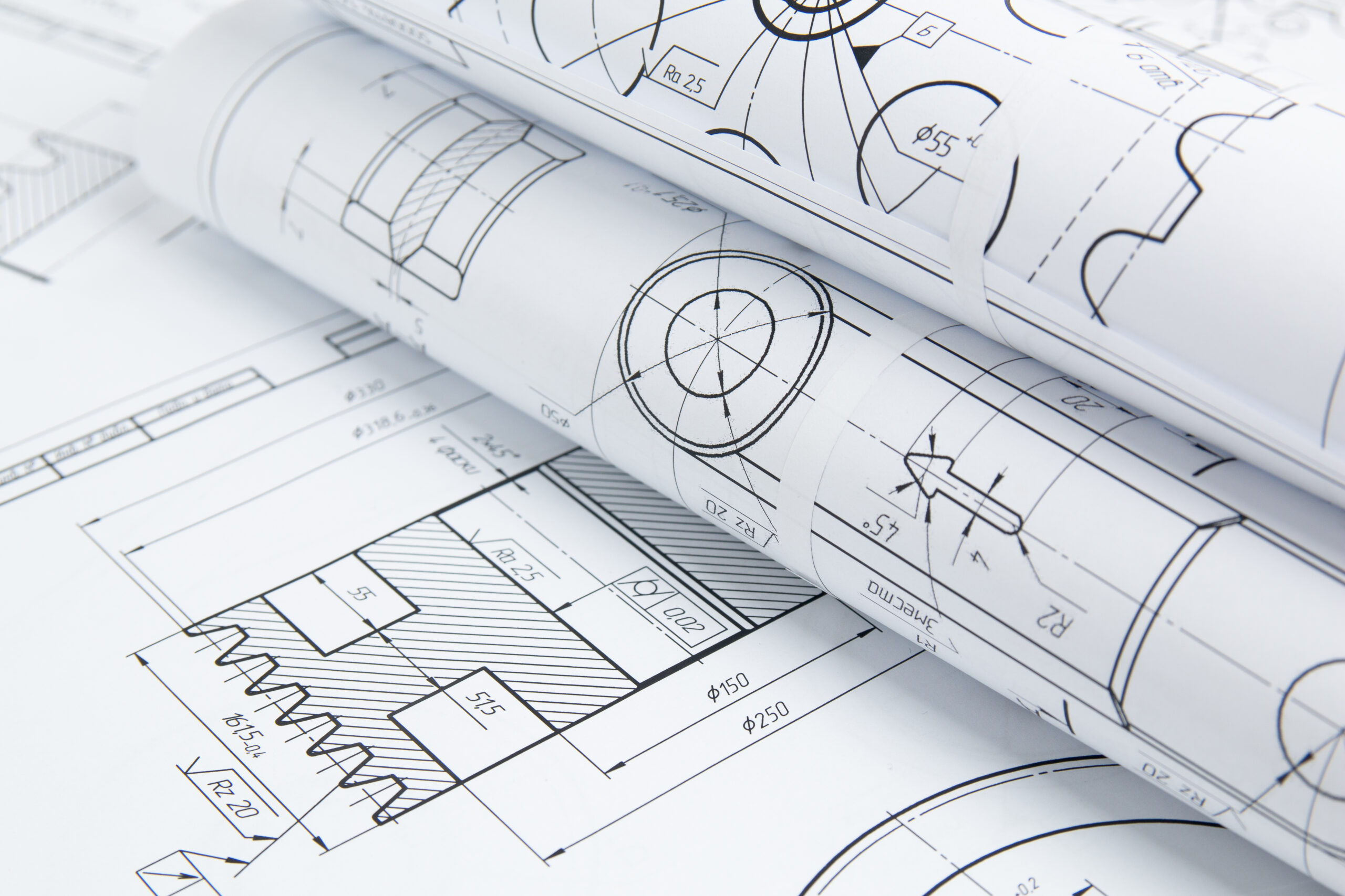
Cylindricity Feature Control Frame
The feature control frame (FCF) is the standard method for annotating a tolerance on an engineering drawing. It typically consists of distinct compartments that define the symbol, the tolerance value, and the reference datums. Thus, all information needed to define a feature is contained within this frame completely.
For cylindricity, the FCF connects to the feature using a leader arrow. Since this tolerance strictly controls the surface form, the leader arrow must always point to the cylindrical surface itself or its extension line (not the dimension line).
The frame is divided into the following three distinct blocks:
1. GD&T Symbol Block
The GD&T symbol block houses the standard geometric characteristic symbol defined by ASME Y14.5.
- The cylindricity symbol consists of a circle sandwiched between two parallel, slanted lines (/○/).
- This icon immediately tells the machinist and inspector that the feature must be treated as a single cylindrical surface, controlling both roundness and straightness simultaneously.
2. Tolerance Value Block
The second compartment defines the specific limits of the tolerance. This block contains the numerical value that dictates the width of the tolerance zone.
In the case of cylindricity, the tolerance value represents the radial separation between the two concentric cylinders. It defines the total width of the wall in which the surface must lie.
Unlike a size tolerance or position tolerance, the cylindricity zone is a Total Wide Zone (also known as a Total Tolerance Zone). It is effectively a 2D flatness zone wrapped around a cylinder.
Because this is a radial width and not a cylindrical boundary size, no diameter symbol (Ø) is used in this compartment. Any tolerance zone without a symbol is assumed to be a total wide zone by default.
Material modifiers (such as MMC or LMC) do not inherently apply to the cylindricity tolerance. The control is applied Regardless of Feature Size (RFS), meaning the form tolerance remains constant regardless of whether the part is produced at its largest or smallest allowable size.
3. Datum Block (Not Applicable)
The third area of a feature control frame is typically reserved for datum references (e.g., A, B, C). However, for cylindricity, this block is left empty.
- Cylindricity is a “pure form” control. It assesses the shape of the feature independently of its location or orientation in 3D space.
- As long as all points on the surface lie within the specified coaxial tolerance zone, the part is considered acceptable. Its angle relative to a base or its distance from a wall does not affect the cylindricity rating, rendering datums redundant.
Cylindricity vs Other Tolerances
Cylindricity is a powerful “compound” control that simultaneously evaluates roundness, straightness, and taper. Because it overlaps with several other geometric controls, it is often confused or misused.
The table below summarizes the key differences at a glance:
| Control | Type | Key Difference vs. Cylindricity | Best Used For |
| Circularity | Form (2D) | Controls only individual cross-sections, not the straightness of the axis. | Sealing rings, short bushings. |
| Straightness | Form (2D) | Controls only surface lines or the axis, not roundness. | Guide rails, long bars. |
| Position | Location | Controls the location of the axis, not the shape of the surface. | Bolt holes, mating pins. |
| Concentricity | Location | derived axis control. Does not control the surface form directly. | Balancing rotating masses. |
| Total Runout | Runout | Controls form + location relative to a datum axis. | Rotating shafts in assemblies. |
As discussed earlier, cylindricity controls the round cross-section, axis straightness, and the overall barrel shape of the cylindrical part.
Let’s review a clear, practical comparison between cylindricity and other (partly) similar controls.
Cylindricity vs. Circularity
Cylindricity is the 3D equivalent of Circularity.
- Circularity (2D): Only checks if individual cross-sections are round. It does not check if they are aligned. A part could be bent like a banana and still pass circularity.
- Cylindricity (3D): Checks the entire surface. To pass, the part must be round and straight.
Circularity can be applied to any circular or spherical features whereas cylindricity works with cylindrical parts only.
Cylindricity vs. Straightness
Straightness controls lines, not volume. It is also a 2D form control.
- Straightness ensures that surface elements or the axis are straight. It ignores the cross-sectional shape.
- Imagine cutting a cylinder in half lengthwise. The resulting semi-circular part would still pass a Straightness inspection (the axis is straight), but it would fail Cylindricity immediately because the cross-section is no longer a circle.
Cylindricity vs. Position
The position control is a type of location control that specifies the location of a feature’s axis with respect to reference points or axes known as datums. It is similar to cylindricity in that they both have the same shape of the tolerance zone (cylindrical). However, these controls serve opposite functions.
Cylindricity is a feature’s shape and is not affected by its position in 3D space. The position control, on the other hand, is opposite.
- Cylindricity controls form (shape). It ignores the location of the part in 3D space.
- Position controls feature’s location. It ignores the shape of the surface.
- A part with a perfectly straight axis (like a pyramid from base to apex) could satisfy a Position tolerance because the axis is in the right place. However, it would fail Cylindricity because the shape is not a cylinder.
Cylindricity vs. Concentricity
Concentricity is a derived axis control, not a surface control.
- Concentricity ensures that the median axes of cylindrical/circular features lie within the defined tolerance zone.
- An oval or “peanut-shaped” part could theoretically pass Concentricity if its opposing points are symmetric around the axis. It would fail Cylindricity because the surface itself is not round.
- Concentricity is even harder to inspect than cylindricity because more cross-sections need to be measured to find the median axis and generally removed from modern standards (ASME Y14.5-2018) in favor of Position or Runout.
Cylindricity vs. Runout
Cylindricity vs. Circular Runout
Circular runout is used to control the wobble of a part during rotation. However, unlike cylindricity that ensures that the entire length has circular cross sections, circular runout is only applied at individual cross-sections.
Cylindricity vs. Total Runout
These are functionally similar, but the difference lies in the datum.
- Cylindricity approves a part as long as it is round and straight, even if it is built at the wrong angle or offset.
- Total Runout requires the part to be round, straight, and perfectly aligned with a datum axis (center of rotation). If the part is intended to rotate in an assembly, Total Runout is the superior choice.
Applying Cylindricity
Cylindricity is a relatively common tolerance for critical components like shafts, pins, and cylinder liners. However, it is also one of the most difficult tolerances to inspect. Its unwarranted use can skyrocket manufacturing costs.
To prevent over-tolerancing, engineers should strictly follow these guidelines on when to apply it and when to avoid it.
When to Use Cylindricity?
You should use the cylindricity callout in the following scenarios:
- When Leak-Free Sealing is Non-Negotiable: This is the primary use case. Cylindricity performs exceptionally well for high-pressure hydraulic applications, such as rams, cylinder liners, and valves. By ensuring the surface is perfect along its entire length, it minimizes leakage risks.
- For Precision Sliding Fits: It is ideal for controlling sliding parts like shafts, bearings, and bushings. It ensures the part moves smoothly without binding or losing energy to friction.
- To Control Roundness and Straightness Simultaneously: Instead of applying two separate controls (Circularity + Straightness), Cylindricity combines them into a single callout. This keeps the drawing cleaner and defines the 3D form requirement in one symbol.
- When You Only Need to Control Shape: Cylindricity can control a shape much better than most callouts but there is no concept of a median axis or location control.
If the part is free-floating (not attached to a datum structure) and you only care about its form, cylindricity is the most accurate definition of a “perfect cylinder.”
When to Avoid Cylindricity?
Cylindricity is a powerful tolerance but it has certain limitations that leads to it being misunderstood and difficult to inspect. These caveats can sometimes lead to manufacturers choosing multiple callouts such as size and position to replace a single cylindricity tolerance.
It is prudent to avoid cylindricity it in these situations:
- When Axis Location is Important: Cylindricity ignores location. It measures the surface against a calculated “best-fit” axis, not a real datum. If a pin needs to align perfectly with a hole, a part could pass Cylindricity but still be out of position, leading to assembly failure. In these cases, use Position or Total Runout.
- When Inspection is Difficult or Limited: Cylindricity requires full-length, high-density scanning (CMM or Roundness Tester). There are no simple functional gauges for it. If you apply this to very long parts, inspection time and data volume increase exponentially.
- When “Bonus Tolerances” are Needed: Unlike Straightness or Position, Cylindricity does not allow the use of the Maximum Material Condition (MMC) modifier. There is no “Bonus Tolerance.” If you need flexibility for assembly, choose a different control.
- When Total Runout Can Do the Job: If a part rotates around a fixed datum axis (like a drive shaft), Total Runout is almost always the better choice. It controls form and alignment relative to the bearings. Using Cylindricity here often leads to false passes (good shape, bad alignment) or unnecessary failures.
Engineering Note: Use cylindricity sparingly. Since the symbol itself does not explain why it is there, it is good practice to provide drawing notes describing the functional requirement (e.g., “Critical Sealing Surface”).
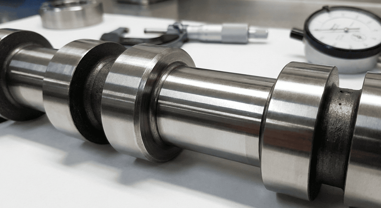
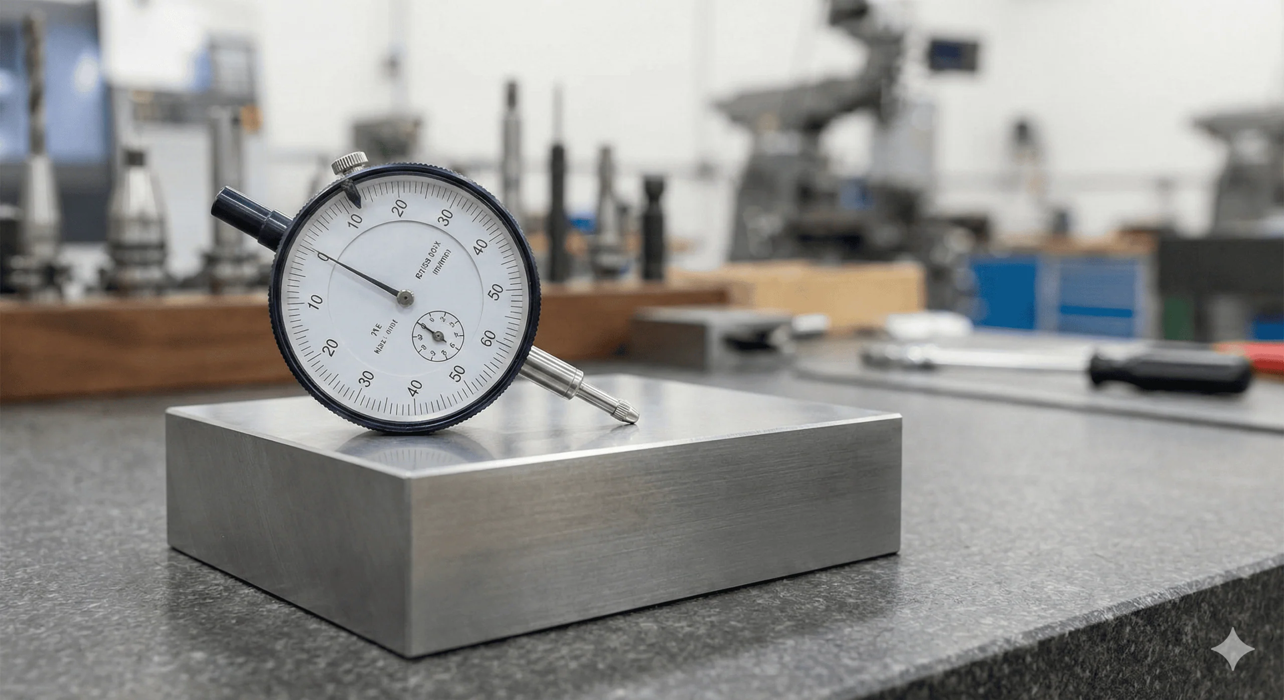
How to Measure Cylindricity?
Measuring cylindricity is significantly more complex than checking diameter with a caliper. Since it requires verifying the entire surface area (3D) relative to a central axis, simple hand tools are insufficient.
1. Roundness Testing Machine (Turntable)
This is the gold standard for verifying cylindrical form.
- The part is mounted on a precision rotating turntable. A probe touches the surface and moves vertically (Z-axis) while the part rotates.
- The machine maps a spiral topography of the surface. Software then calculates the Minimum Radial Separation between two concentric cylinders that contain all surface points.
2. Coordinate Measuring Machine (CMM)
The CMM is the most common industrial method for this control.
- The probe moves around the stationary part, collecting a “point cloud” using a helical scan path or multiple circular traces at different heights.
- Algorithms (typically Least Squares or Minimum Zone) process the data to determine the deviation.
3. 3D Scanning
3D scanning is a non-contact method for measuring cylindricity.
- A light or laser is projected onto the part, and the reflection is measured to create a 3D point cloud.
- Perfect cylinders are mathematically fitted to this point cloud to find the minimum and maximum radii that contain all surface points. The difference between these radii is the cylindricity value.
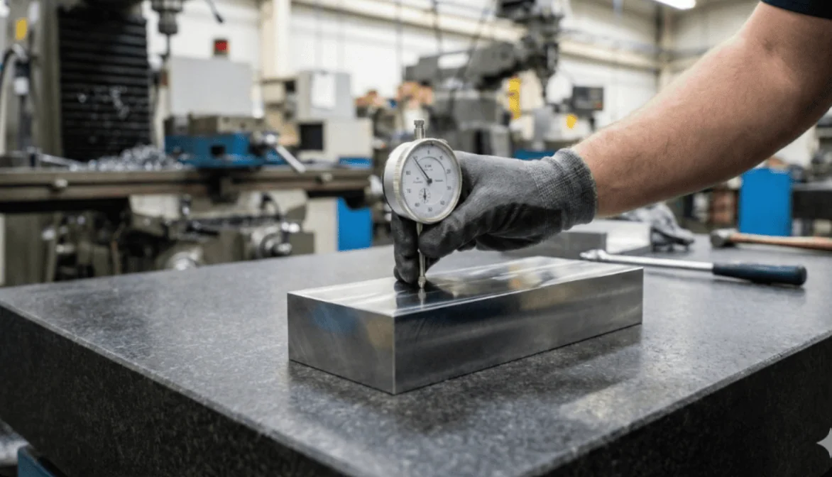
Why V-Blocks are Not Recommended
A common shop-floor mistake is trying to measure cylindricity using a V-block and a dial indicator.
- The Problem: V-blocks cannot detect “Lobing” (e.g., a triangular shape with rounded corners). A lobed part can rotate in a V-block and show a constant diameter reading, falsely passing inspection.
- The Verdict: V-blocks measure Circular Runout relative to the setup, not true Cylindricity.
Relation to Size Tolerance
Per the Envelope Principle (ASME Y14.5 Rule #1), unless otherwise specified, the form of a feature must not extend beyond its perfect boundary at Maximum Material Condition (MMC).
The Golden Rule: The Cylindricity tolerance must always be less than the Size (Diameter) tolerance.
- Example: If a pin has a diameter tolerance of 0.2 mm, the cylindricity tolerance must be tighter (e.g., 0.05 mm).
- Invalid Callout: If you set cylindricity to 0.3 mm, you are logically allowing the surface to warp outside its own size limits.
Glossary of Key Terms
| Term | Definition | Context |
| Coaxial Cylinders | Two cylinders sharing the same axis but with different diameters. | The shape of the Cylindricity tolerance zone. |
| Radial Separation | The distance between the inner and outer cylinders of the tolerance zone. | This is the value entered in the Feature Control Frame. |
| Lobe / Lobing | A form error where the cross-section is not round (e.g., triangular). | Common in centerless grinding; undetected by 2-point measurement tools (calipers). |
| Total Wide Zone | A tolerance zone that applies to the entire surface area. | Cylindricity uses a Total Wide Zone (no diameter symbol). |
Mastering Form Controls
Cylindricity is one of the ultimate GD&T form controls for shafts, pins, bearings, and bores, ensuring they are both round and straight. However, due to the difficulty of inspection, it should be used judiciously.
- Vs. Circularity: If you don’t need to control axis straightness, use Circularity to save inspection time.
- Vs. Runout: If the part rotates in an assembly (like a motor shaft), Total Runout is often the better functional choice.


Comment(0)