 Europe
  Türkiye
  United Kingdom
  Global


 0
0

The correct use of GD&T eliminates confusion in engineering drawings by providing clear instructions on how to manufacture and inspect a part. Within this system, Circularity is a fundamental Form Control. Like straightness, flatness, and cylindricity, it applies strictly to the 2D shape of the feature itself and does not require a datum reference.
What is Circularity in GD&T?
The GD&T Circularity tolerance is a two-dimensional form control that ensures a circular feature is round enough to meet functional requirements at every individual cross-section of the feature.
Because circularity evaluates each cross-section independently, it does not control the straightness of the feature’s axis or the overall cylindrical shape of the part. The tolerance controls the feature by defining a tolerance zone for each measured cross-section of its surface. A surface meets the tolerance only if all points lie within the tolerance zone.
In addition to standard circular features such as pins and bores, circularity can also control circular features of spherical and conical parts.
As with other form controls, circularity is defined without a datum axis. The location of a feature is not important as the form control only governs a feature’s shape. A feature could be in a completely wrong location but still perfectly pass the circularity control. For isolated components, such as simple shafts, this is completely fine as the circular feature is a complete part in itself. However, for components that need to have a circular feature in addition to other features, location tolerances may be added to ensure precise positioning.
Note: As a practical rule, circularity should typically be equal to or tighter than the feature’s size tolerance; otherwise it may be redundant and add inspection cost without improving function.
When to Apply Circularity?


The circularity tolerance is a great tool for controlling roundness in circular features. In practice, circularity is suited to parts where the circular shape is absolutely critical for function. It is commonly applied to pipes, spools, bearings, and shafts to ensure:
- Good sealing: Pistons, rams, spools, and cylinders must achieve effective sealing and have good fluid control in hydraulic systems.
- Tight assembly: Precision pins must fit securely and reliably in assemblies, especially in case of close engineering fits.
- Smooth rotation: Vibrations and wobble must be minimal in parts such as turbine rotors, axles, and shafts. This also improves transmission efficiency by controlling friction resistance.
- Uniform load distribution: Bearings must distribute load evenly to prevent premature wear and damage to machinery. Ideally, the wear is even and controlled.
Through circularity, we can loosen diametral tolerance while still meeting functional requirements that demand a near-perfect circular feature. Let us understand how circularity is used in the industry through an example.
Circularity Application Example from the Industry
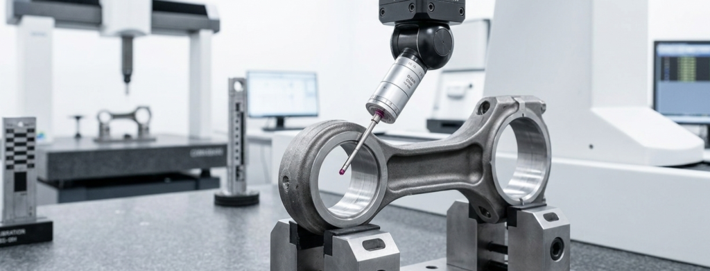
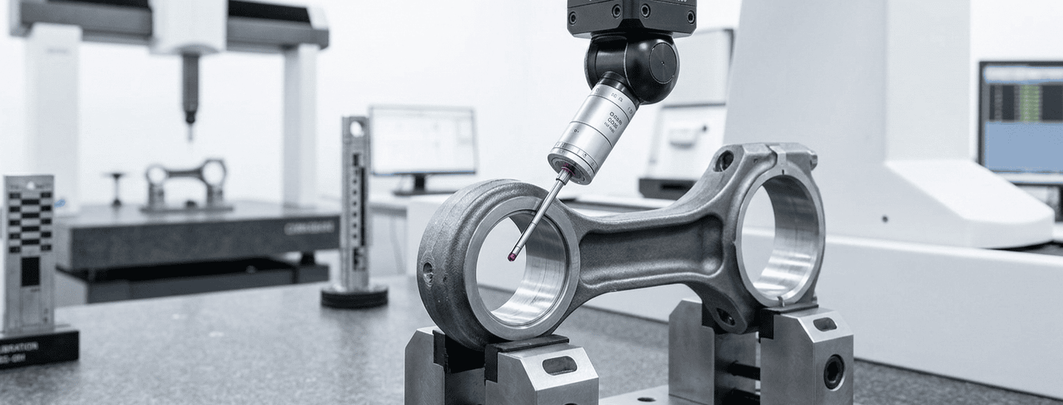
To understand the critical nature of this form control, look no further than the connecting rod of a generator engine. This component operates at high speeds under tremendous cyclic loads for days or weeks at a time. It performs the vital function of converting linear motion into rotational motion by transferring explosive forces from the combustion cylinder to the crankshaft.
The bores on the small and large ends of the connecting rod are responsible for power transfer, even load distribution, and the maintenance of a uniform oil thickness for lubrication. These bores must be circular enough to maintain the microscopic clearances necessary for hydrodynamic lubrication.
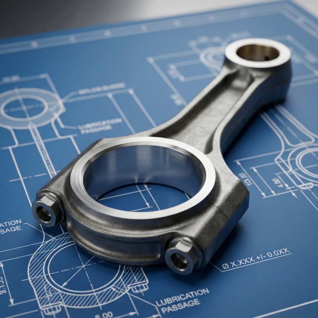

A perfectly round bore ensures minimal vibrations and strictly controlled bearing wear. Even the smallest amount of ovality (out-of-roundness) in the connecting rod can amplify within hours, resulting in catastrophic engine failure. Therefore, these critical bores are manufactured with strict circularity tolerances to ensure negligible ovality.
In many engine applications, allowable ovality limits are extremely small, often only a few hundredths of a millimeter. Typical service limits reported in engine maintenance references fall roughly in the range of 0.015 mm (0.0006″) to 0.025 mm (0.001″), although the exact value always depends on the specific engine design and manufacturer specifications. Because this dimension directly affects bearing load distribution and oil film stability, connecting rod bores are typically inspected during major engine overhauls and replaced if ovality exceeds manufacturer limits.
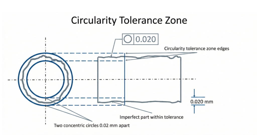
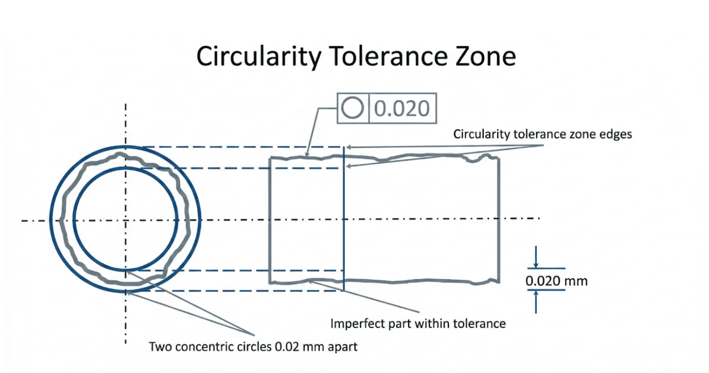
Circularity Tolerance Zone
The circularity tolerance zone is a 2D boundary defined by two concentric circles. To pass inspection, all points on the surface of the feature’s cross-section must lie entirely within the radial space (the gap) between these two circles.
The plane of this tolerance zone is always perpendicular to the axis of the circular feature under control. Note: Because Circularity evaluates form independently of the part’s actual axis, the phrase “perpendicular to the axis” is used conceptually for visualization.
Because Circularity is a 2D control, this tolerance zone is evaluated independently at multiple cross-sections along the length of the part. Each cross-section must independently fall within its own tolerance zone; passing one cross-section does not guarantee that the entire feature meets the circularity requirement.
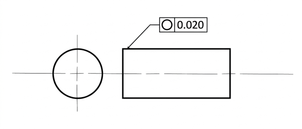
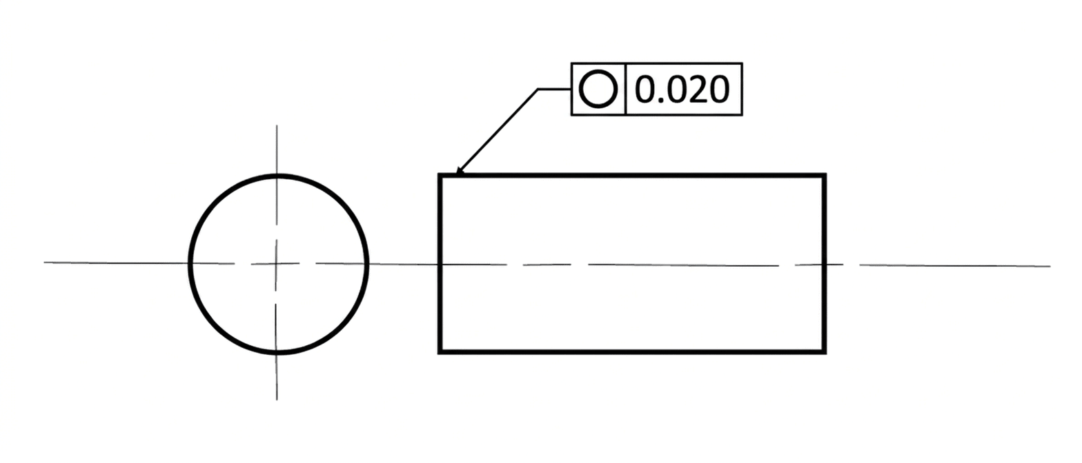
How to Apply Circularity (Feature Control Frame)
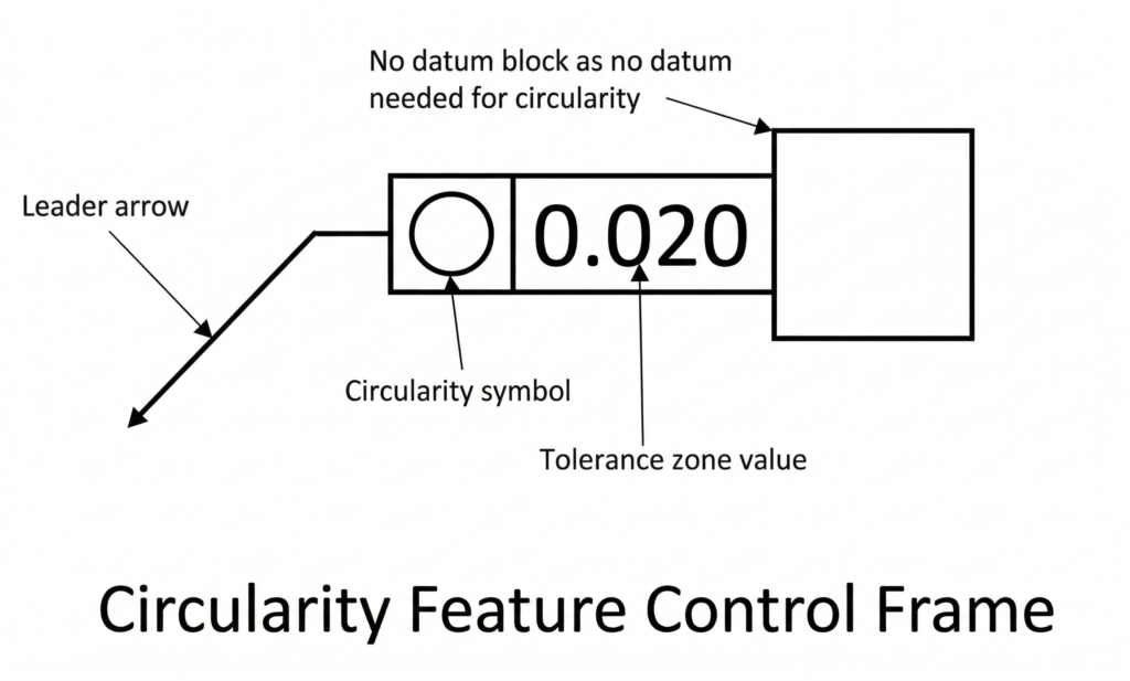
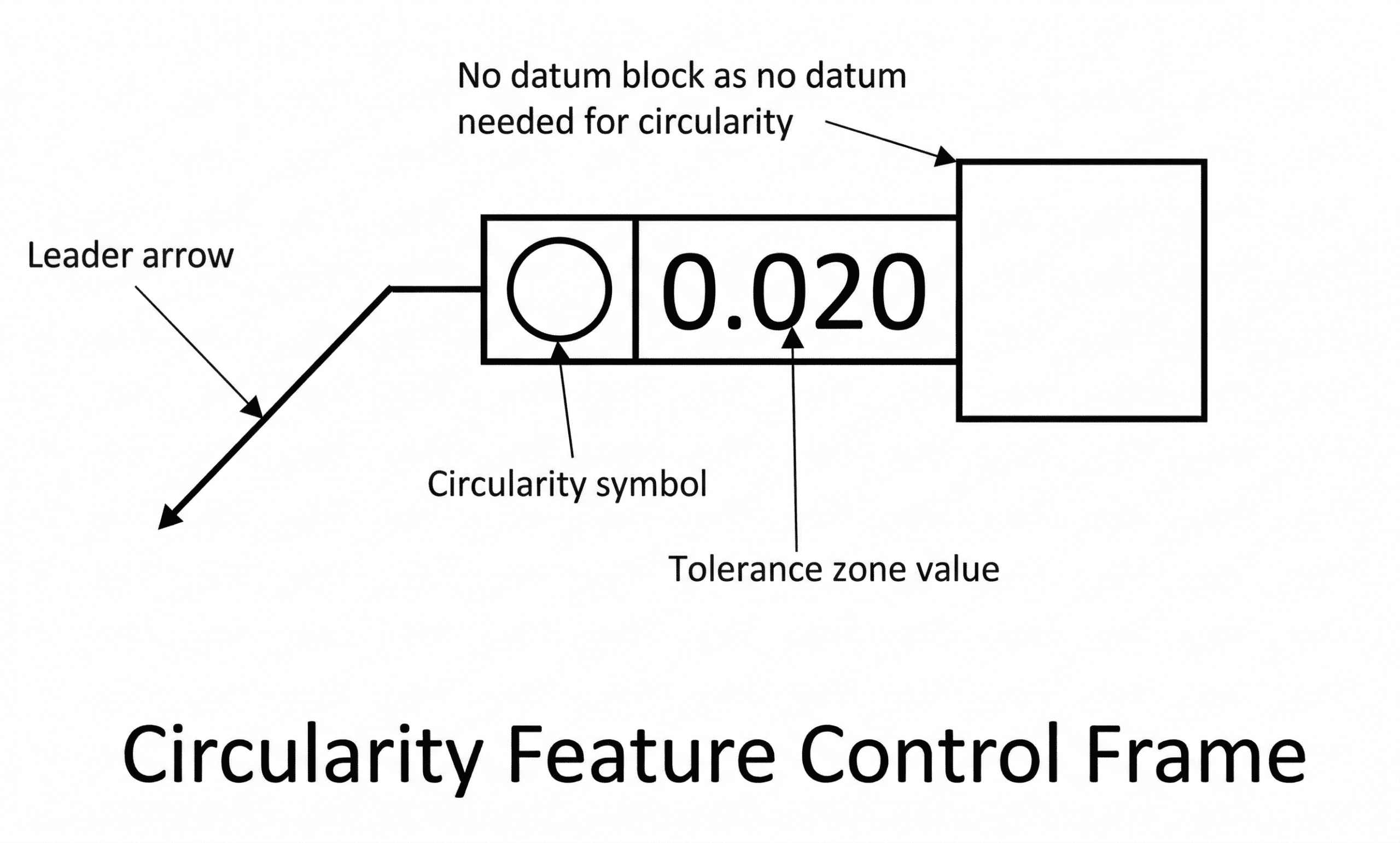
GD&T tolerances are communicated on engineering drawings using a Feature Control Frame (FCF). This frame uses a standard layout to concisely explain the tolerance value, zone shape, and material conditions. The FCF connects to the feature using a leader arrow (or leader line) pointing directly to the surface being controlled.
A standard feature control frame for circularity is broken down into specific blocks:
1. GD&T Symbol Block
The first compartment houses the geometric characteristic symbol. For circularity, this symbol is a simple, perfect circle (○).
2. Tolerance Value Block
The second compartment defines the total allowable variation. This numerical value dictates the radial gap between the two concentric circles that make up the tolerance zone.
- No Zone Symbol: Because circularity uses the default 2D tolerance zone, no specific zone shape symbol (like a diameter symbol) is required in this block.
- Regardless of Feature Size (RFS): The circularity tolerance is fixed and does not change based on the feature’s actual manufactured size. Therefore, circularity is always applied Regardless of Feature Size (RFS), and is never applied with material modifiers like Maximum Material Condition (MMC) or Least Material Condition (LMC).
3. Datum Block (Not Applicable)
The third compartment of an FCF is usually reserved for datum references (fixed points, axes, or planes). However, because the circularity tolerance is a pure form control that strictly evaluates the shape of the part, it has nothing to do with feature location or orientation. Thus, the feature control frame for circularity does not contain a datum block.
Circularity vs. Other Tolerances
Circularity is a powerful form control, but because it evaluates cross-sectional roundness, it is often confused with other GD&T callouts. To apply it correctly and avoid unnecessarily driving up manufacturing costs, it is vital to understand where the differences lie.
The table below summarizes the key differences at a glance:
| Control Type | Category | Key Difference vs. Circularity | Best Used For |
| Circularity | Form (2D) | Controls only 2D cross-sectional roundness. No datum required. | Sealing rings, individual cross-sections. |
| Cylindricity | Form (3D) | Controls roundness and straightness of the entire 3D cylinder. | Long shafts, tight-fitting sliding pins. |
| Concentricity | Location | Controls the location of the median axis, not the shape of the surface. | Balancing rotating masses (Legacy). |
| Runout | Location & Form | Controls roundness and eccentricity relative to a fixed datum axis. | Rotating shafts in active assemblies. |
Circularity vs. Cylindricity
Circularity and cylindricity both control the roundness of cross-sections. However, cylindricity also ensures that a part has a sufficiently straight axis. Thus, cylindricity is the 3D equivalent of circularity.
Imagine a stack of coins. Since circularity is checked independently at each cross-section, the part will pass inspection as long as each coin is perfectly round. Even if the coins are misaligned and jutting out in different directions, the part still passes the 2D Circularity check. This same stack of coins, however, would immediately fail a 3D Cylindricity check, because the misaligned coins shift the overall axis far enough that the total volume no longer resembles a perfect cylinder.
Circularity vs. Concentricity
Circularity and concentricity appear similar at first but serve entirely different geometric purposes.
- Form vs. Location: Circularity is a form tolerance that is indifferent to the feature’s location. Concentricity is a location tolerance.
- The Tolerance Zone: The circularity tolerance zone is a 2D ring-shaped zone surrounding the physical surface. Concentricity’s tolerance zone is a 3D cylindrical envelope positioned along a theoretical axis.
The primary objective of circularity is to ensure that the physical part maintains a circular shape. If the part deviates by becoming elliptical or oblong, it will face rejection. Concentricity, on the other hand, strictly measures the location of a feature’s median axis. A part could actually be elliptical (failing circularity) but still pass a concentricity check as long as its median axis remains perfectly centered within the tolerance zone.
Because concentricity measures location, it requires a datum axis. Circularity requires no datum feature. (Note: In modern GD&T practice, concentricity is rarely recommended. Many applications now use Position or Runout controls instead because they are easier to inspect and communicate.)
Circularity vs. Runout
The runout tolerance essentially combines a circularity callout and an eccentricity (off-center) check into one dynamic inspection.
Let us think about it this way: A part may pass circularity checks at each cross-section, but its actual axis may deviate significantly from the central assembly axis, causing the part to wobble when spinning. Conversely, a part’s median axis may coincide perfectly with the central axis, but it does not have a circular cross-section (it is oval). In both cases, if the part rotates at high speeds, it will be subjected to undue stresses, leading to premature degradation or catastrophic failure.

Runout addresses this issue by evaluating both the surface form and its relationship to a reference axis during rotation. It measures a part’s eccentricity (being off-center) as well as its surface form. If a part is perfectly round, the runout value represents its eccentricity. If it is perfectly centered, runout measures its circularity. For most real-world parts, a runout measurement captures the sum total of both circularity and eccentricity errors.
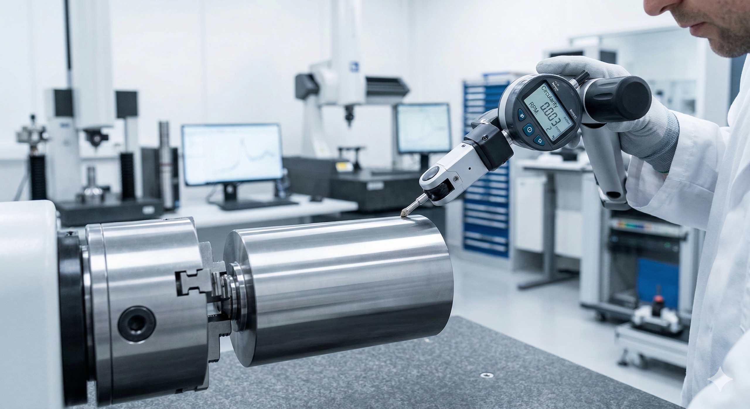
How To Measure Circularity
Circularity is measured at multiple cross-sections independently. The inspector must measure the highs and lows to ensure that the part does not have excessive circularity error in either radial direction around the cross-section.
Reliable circularity measurements are possible through the following five methods, ranging from standard shop-floor setups to advanced metrology:
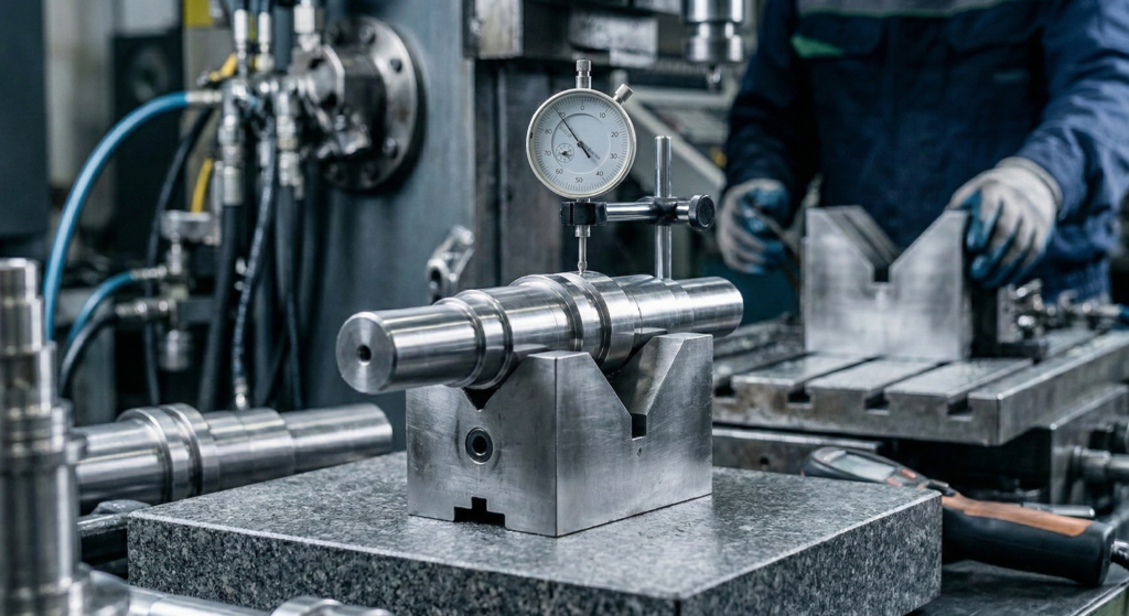
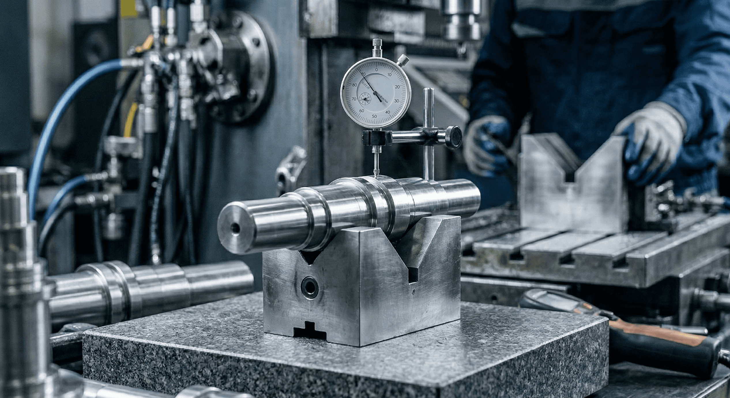
1. Height Gauge and V-block
Circularity can be approximated by identifying the overall high and low points on a cross-section and dividing the difference by two. The division by two is necessary because the measurements capture the total run across the tolerance zone on both sides of the part.
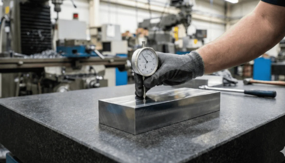
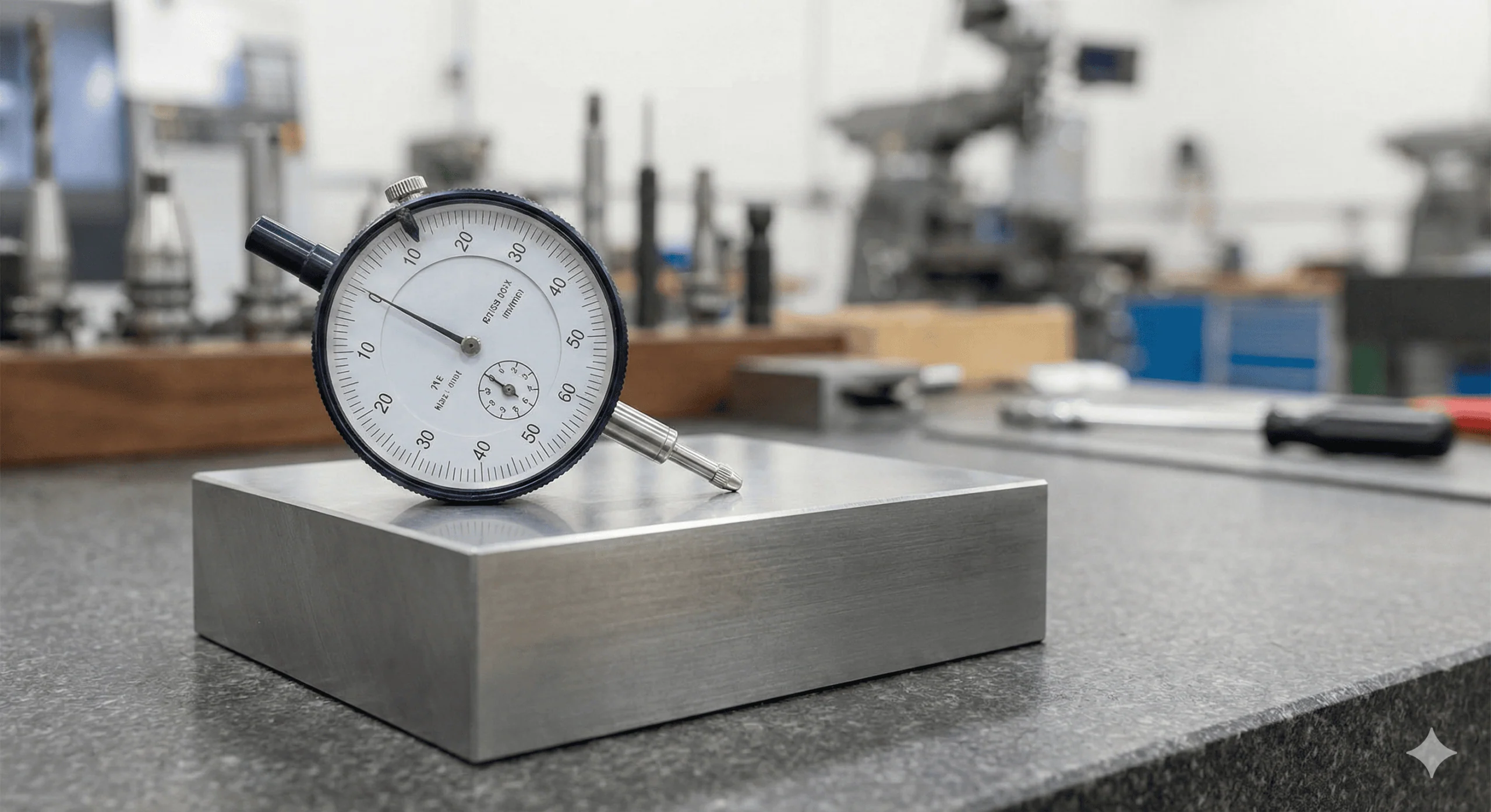
This makes circularity relatively straightforward to check, and it is quite common to see measurements performed using a rudimentary setup with a dial gauge and a V-block.
- To measure circularity, place the cylindrical part on a V-block.
- Bring the dial indicator into contact with the top surface and zero it.
- Slowly rotate the part 360 degrees, noting the maximum and minimum indicator readings.
- The circularity value is half the difference between these two readings.
This method is prone to issues like error magnification and true axis misidentification, and it struggles with very tight tolerances. Therefore, it is best suited for general applications, quick on-machine measurements, and large parts.
Note: Dial indicator methods measure variation relative to the setup and effectively capture Total Indicator Reading (TIR). While useful for quick shop-floor checks, this approach does not fully replicate the formal roundness evaluation methods used in precision metrology.
2. Micrometer
The micrometer uses a two-point measurement principle similar to the V-block method. The outer diameter (OD) is measured all around the 2D cross-section, and the difference between the maximum and minimum readings is divided by two.
Note: 2-point micrometers cannot detect odd-numbered lobing (shapes with a constant diameter but non-circular form). They will falsely pass these defective parts, so a V-block or CMM should be used instead.
3. Coordinate Measuring Machine (CMM)
The CMM is a preferred tool for macro-geometry measurement. It can measure circularity with high accuracy, repeatability, and reliability. Depending on the scale of the programmed inspection path, the CMM can cover the entire surface, making it the go-to choice for special parts that need to meet tight, complex aerospace or automotive standards.
4. Dedicated Roundness Tester
For absolute precision, dedicated roundness testers (profilometers) are the most appropriate solution. A roundness tester is a special instrument designed specifically to measure the deviation of a part’s cross-section from a perfect circle.
It can measure the complete circumference using a highly sensitive rotating probe, making it perfectly suited for form tolerances like circularity and cylindricity. The tester traces the part’s physical profile, which is then mathematically compared against a perfect circle by the system’s software. The instrument outputs the data in the form of a highly detailed topographic graph or a precise numerical value.
5. 3D Scanning
3D scanning offers an advanced, non-contact method for circularity measurements. It projects light or lasers to create a highly detailed 3D point cloud of the part, which is then fitted onto perfect virtual circles using metrology software. The software quantifies the roundness value using advanced algorithms such as the least squares or minimum zone methods.
This non-contact approach can provide useful roundness data when the scanner resolution, surface condition, and measurement setup are appropriate. However, for tight circularity tolerances, dedicated roundness testers or high-precision CMM measurements are typically preferred.
Glossary of Key Terms
| Term | Definition | Context |
| Concentric Circles | Two circles sharing the exact same center point but with different radii. | Defines the 2D boundary of the Circularity tolerance zone. |
| Radial Separation | The physical distance (gap) between the inner and outer concentric circles of the tolerance zone. | This is the specific numerical value entered into the Feature Control Frame. |
| Lobe / Lobing | A form error where the cross-section is not perfectly round (e.g., it resembles a rounded triangle or oval). | A common defect in centerless grinding; completely undetected by simple 2-point measurement tools like calipers. |
| RFS (Regardless of Feature Size) | The rule stating that the geometric tolerance remains fixed, regardless of the part’s actual manufactured size. | Circularity is always RFS. Material modifiers (MMC/LMC) and bonus tolerances cannot be used. |
| Cross-Section | A 2D “slice” of a 3D part, perpendicular to its axis. | Circularity evaluates the part one 2D slice at a time, entirely independent of the rest of the cylinder. |
Mastering Form Controls
Circularity is one of the most fundamental GD&T Form Controls for ensuring precision fits, smooth rotation, and proper sealing. To create fully manufacturable parts, engineers must understand how it interacts with the rest of the GD&T ecosystem:
- Vs. Cylindricity: If you need to ensure the part is perfectly round and that its central axis is perfectly straight along its entire length, step up to Cylindricity.
- Vs. Total Runout: If the part is designed to rotate at high speeds within an assembly (like a motor shaft or turbine), and you must control its wobble relative to a fixed bearing axis, use Total Runout.
- Vs. Straightness: If you only care about the linearity of the part’s axis and do not explicitly need to control the roundness of its cross-sections, use Straightness.
For deeper insights into these related controls and how to apply them to your CAD drawings, explore our comprehensive Geometric Dimensioning and Tolerancing guide in the Xometry Pro technical library.


Comment(0)