 Europe
  Türkiye
  United Kingdom
  Global


 0
0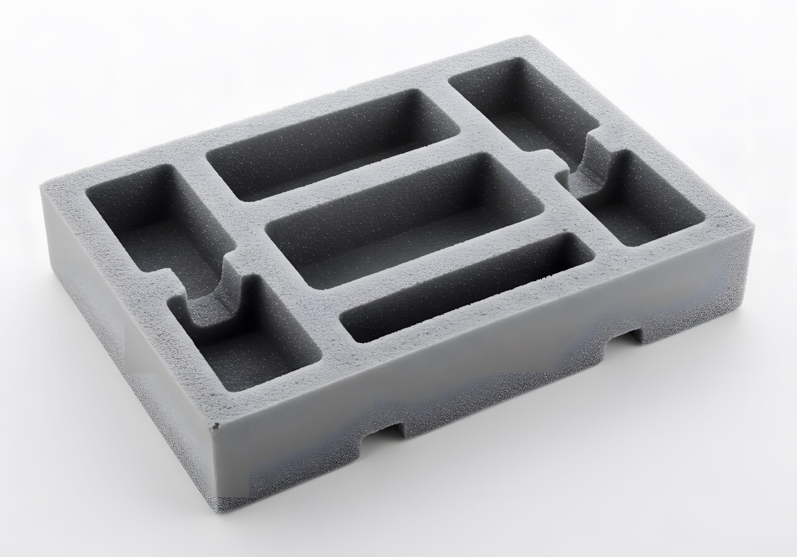
What Is Foam Injection Molding?
Foam molding—also known as structural foam molding—produces rigid plastic parts with an internal cellular core and a solid outer shell. This structure reduces material use and part weight up to 30% while preserving strength and dimensional stability. Engineers use it to manufacture large, rigid components that need to stay lightweight—like dashboards, housings, and panels.
As a rule of thumb, use foam molding when:
- Part size is large
- Weight reduction is critical
- Surface finish is not cosmetic
The process blends molten thermoplastic with a chemical or physical blowing agent. Inside the mold, a controlled pressure drop causes the agent to expand, forming uniform gas bubbles (~4 mm diameter). This expansion creates a lightweight internal structure without compromising strength.
Unlike traditional injection molding, foam molding keeps the foaming process tightly controlled. Expansion happens only after the material fills the cavity. This enables efficient plastic use and supports thicker, more complex geometries that solid molding can’t handle.
Thermal insulation and sound damping are additional benefits—especially important in automotive and aerospace interiors.
| Advantages | Disadvantages |
| Up to 30% weight reduction | Longer cycle times due to foam expansion |
| High strength-to-weight ratio | Surface defects like swirl marks may occur |
| Excellent thermal & acoustic insulation | Higher tooling and setup costs |
| Supports large, complex geometries | Limited surface finish quality for cosmetic applications |
| Lower material use and waste | Fewer compatible materials compared to standard molding |
Technical Specifications of Foam Injection Molding
Use the following design rules and parameters to ensure high-quality foam-molded parts:
| Parameter | Design Guidance |
| Materials | Use expanded thermoplastics such as EPP, EPS, EPO. Choose based on mechanical needs, flexibility, and thermal resistance |
| Build Size | Parts can reach up to 1,500 mm in length, depending on material and molding setup. Design large components in a single shot when feasible. |
| Wall thickness | Maintain a uniform wall thickness of at least 8 mm. Avoid thick ribs and sharp transitions to ensure even filling and foaming. Use dual-wall designs where necessary. |
| Tolerances | Vary with part density and geometry. Discuss tolerances during DFM to account for foam expansion and shrinkage. |
| Surface Finish | Expect swirl marks or textured areas due to foaming. However, gate vestiges will not appear. Don’t use for high-cosmetic surfaces. |
| Production Volume | Best suited for medium to high volumes—typically from 50 up to 100,000+ units. For prototypes or very low quantities, consider alternative methods. Minimum order quantities depend on the raw material, with both part volume and required quantity playing a key role. |
| Design guidance | • Apply 1° draft per feature height for demolding • Use a 20 mm flat gate surface to ensure proper filling • Optimize rib geometry for smooth flow and full cavity fill |
Foam Molding Compared to Other Manufacturing Processes
Foam injection is unique in many different ways compared to compression molding or traditional processes. Here’s a detailed comparison:
| Technology | Foam Molding | Traditional Injection Molding | Compression Molding |
| Best For | Lightweight structural parts with thick walls and moderate surface demands | Highly detailed plastic parts with tight tolerances and cosmetic finishes | Low-volume rubber or thermoset parts with basic shapes |
| Optimal Quantity Range | > 200 (depending on raw material minimum order quantity) | 50 – 1,000,000 | 1 – 5,000 |
| Lead Time (available at Xometry) |
38 days | 38 days | 20 days |
| Maximum Part Size (available at Xometry) | Typically 1000 × 1500 × 500 mm, but it depends on material and molding method | 1289 × 1910 × 1006 mm | 500×500 mm |
| Mould Life | 10,000 – 1,000,000 shots | 10,000 – 1,000,000 shots | 10,000 – 1,000,000 shots |
| Material Selection | Expanded thermoplastics (EPP, EPS, EPO) | Any thermosets/thermoplastics | Rubbers, silicone materials |
| Prototyping | ⭐ | ⭐ | ⭐⭐⭐ |
| High-Volume Production | ⭐⭐ | ⭐⭐⭐ | ⭐ |
| Part Design Complexity | ⭐⭐ Supports ribs and thick walls |
⭐⭐⭐ Handles thin, complex geometries |
⭐⭐ Simple shapes work best |
| Standard Surface Finish | ⭐⭐ May show swirls or texture |
⭐⭐⭐ Smooth, detailed surfaces |
⭐⭐ Less suited for cosmetic parts |
| Post-Processing | No | No | No |
| Cost of Design Mistakes | Moderate | High | Lower |
| Advantages | • Lightweight, strong parts • Thicker walls without sink marks • Lower material usage • Good thermal/acoustic insulation |
• High repeatability for consistent part quality • Ideal for large production volumes • Extensive material options to suit diverse applications • Ability to meet custom colour requirements, ensuring precise tones |
• Go-to process for specific rubber or thermoset applications, e. g. NBR and FFKM • Cost-effective tooling for production runs of up to 5,000 pieces |
| Disadvantages | • Lower surface finish • Not suited for thin walls • Longer cycle times |
• High upfront investment in mould tooling • High costs for mould modifications or improvements, particularly if the design is not frozen before mould production • Limited flexibility for highly complex or intricate designs |
• Limited material options • Limited design complexity |
Foam Injection Molding Materials
Choose your material based on performance needs, environmental exposure, and design priorities. Below are the most common options with their key traits and ideal applications:
| Material | Key Properties | Applications | Strength & Shape Retention | Use When |
| EPP (Expanded Polypropylene) | • High impact resistance • Lightweight • Good thermal insulation • Chemical and water resistance • Recyclable |
• Automotive components (e.g., bumpers, headrests) • Reusable packaging • HVAC parts • Sports equipment |
• High resilience • Retains shape after multiple impacts |
You need durable, reusable parts that absorb energy and maintain form under repeated stress |
| EPS (Expanded Polystyrene) | • Rigid and lightweight • Excellent thermal insulation • Moisture resistant • Cost-effective |
• Building insulation • Protective packaging • Disposable food containers |
• Moderate strength • Brittle; limited shape retention after impact |
You need low-cost insulation or single-use packaging with minimal structural load |
| EPO (Expanded Polyolefin) | • Blend of polyethylene and polystyrene • Lightweight • Good impact resistance • Moldable into complex shapes |
• Model aircraft • UAV components • Disposable packaging |
• Moderate resilience • Less durable than EPP |
You need parts with complex geometries and moderate toughness—where EPP is overkill |
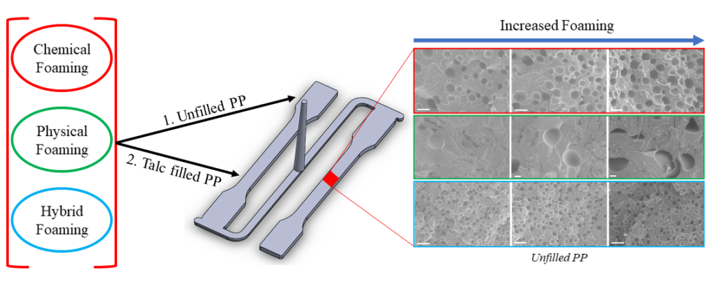
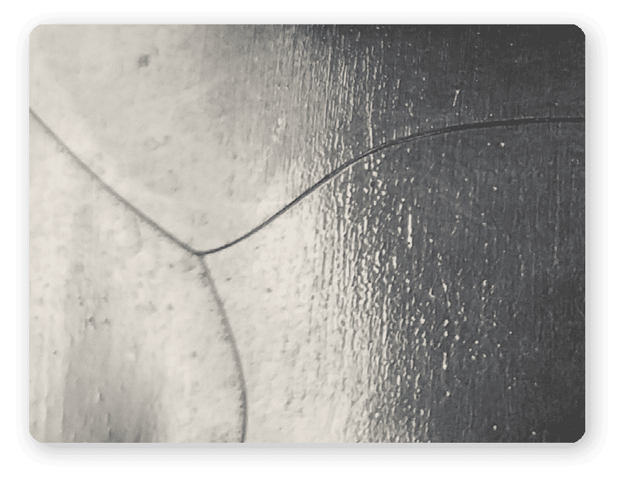
The foaming technique used—chemical, physical, or hybrid—has a direct impact on the material during molding, affecting how it expands and solidifies within the mold. Each method influences the size, distribution, and uniformity of foam cells, which in turn determines the mechanical behavior and performance of the final part.
The diagram below illustrates the effects of these different techniques on polypropylene (PP). The accompanying micrographs show how foam formation increases, with clear variations in bubble size and distribution.

Types of Foam Injection Molding
There are various methods for generating foam within a polymer matrix. These differences influence material properties, processing conditions, and the suitability of applications.
The three main types are:
- Physical foaming
- Chemical foaming
- Structural foaming
Physical Foaming
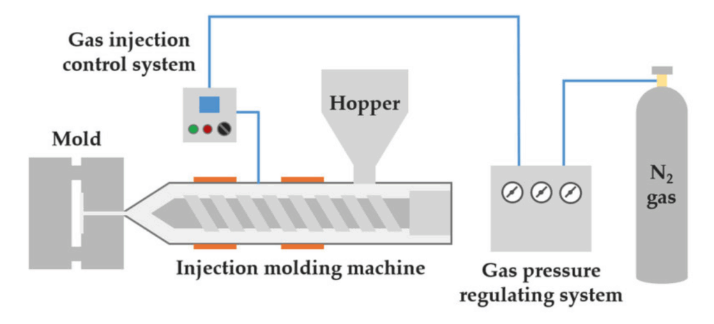
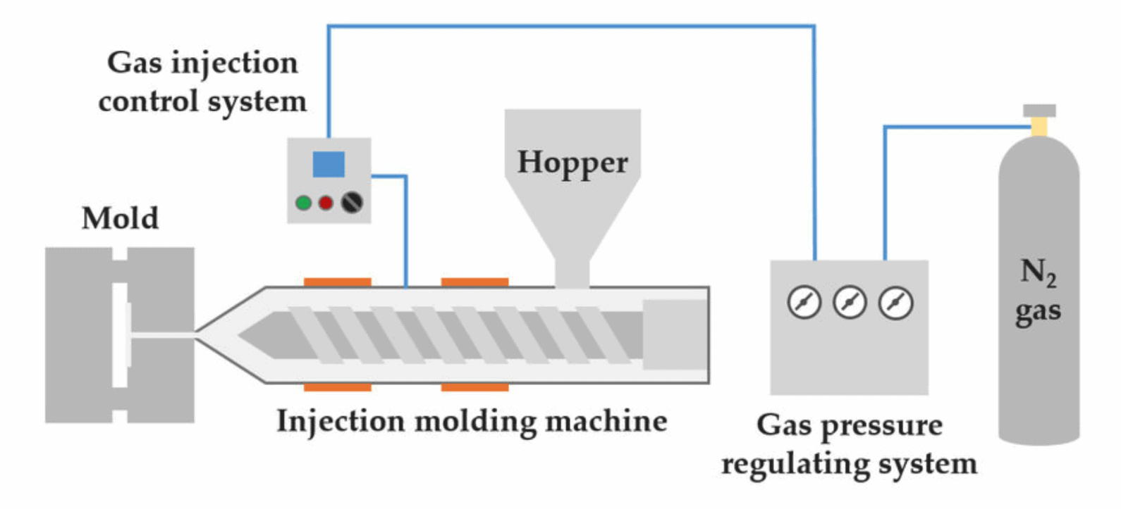
The physical foaming process involves forcing unreactive gas, such as nitrogen or carbon dioxide, into the polymer melt under high pressure. This forces the gas to fuse into the molten polymer. During the injection process, the pressure is reduced, and gas is forced to come out, forming bubbles within the molten polymer.
It is best when you need good finish and no chemicals.
Key Benefits:
- Environmentally friendly process with no chemical reactions involved
- Reduces material usage while maintaining structural integrity.
- Improves surface finish and dimensional stability.
- Allows for the production of complex geometries with uniform wall thickness.
Chemical Foaming
This method uses chemical reactions to produce gas bubbles within the molten polymer. It involves heating chemical blowing agents and a polymer mixture, which releases gas (nitrogen or carbon dioxide) and causes foaming. Chemical foaming is typically the same as other injection molding techniques. Heating, mixing, plasticizing, and most processes occur in an injection molding machine.
Ideal when cycle time and cost are priorities.
Key Benefits:
- Enables precise control over cell size and density through selection of specific chemical blowing agents (CBAs).
- Reduces material usage and part weight, leading to cost savings.
- Improves dimensional stability and reduces warpage.
- Eliminates sink marks, enhancing surface finish.
- Allows for faster cycle times and lower clamping pressures.
Structural Foaming
Structural foaming is a hybrid process that benefits from traditional injection molding and new foaming technology. Chemical or physical blowing agents are used in creating a microcellular foam structure, but chemical agents are mostly used.
The main difference between structural foaming and chemical foaming is the injection pressure. Structural foaming operates at a lower pressure, which allows the core to be foamed as gases expand while the outer layer remains solid.
Best option when you need low-pressure molding for large parts.
Key Benefits:
- Produces parts with a high stiffness-to-weight ratio—lightweight yet durable.
- Enables molding of intricate geometries using low-cost molds.
- Suitable for manufacturing extra-large parts.
- Reduces material usage and cycle times, enhancing production efficiency.
How Foam Injection Molding Works
Foam injection molding combines conventional injection molding with a foaming stage to produce lightweight parts with a cellular core and solid outer skin. The process involves selecting the right material and foaming agent, then carefully controlling temperature, pressure, and mold design to ensure uniform foaming and part quality.
Step 1: Select the Right Polymer
Choose a thermoplastic that matches your performance goals.
- Use EPP for high impact resistance and shape recovery
- Use EPS for rigid, low-cost insulation
- Use EPO for complex geometries with moderate strength
Step 2: Add a Foaming Agent
Choose the foaming method based on cell structure and environmental needs:
- Chemical agents (e.g. azodicarbonamide, sodium bicarbonate) release gas when heated
- Physical agents (e.g. nitrogen, carbon dioxide) are injected under high pressure
Step 3: Inject the Molten Mixture
Heat and mix the polymer and blowing agent into a uniform melt. Then inject it into the mold cavity.
- Maintain tight temperature control to avoid premature foaming
- Use low injection pressure to allow core expansion while the outer skin solidifies.
Result: A part with a smooth surface and lightweight interior.
Step 4: Foaming and Expansion
As the pressure drops inside the mold, the blowing agent expands—forming evenly distributed gas bubbles. Control pressure and temperature to ensure uniform cell size and prevent defects like voids or warping.
Step 5: Cooling and Ejection
Cool the part inside the mold using water channels or integrated cooling systems.
Once solid, eject the part. Perform any secondary operations like trimming or painting as needed.
The Bottomline: Why Use Foam Injection Molding?
Engineers can use foam injection molding to reduce part weight, improve insulation, and cut material costs—without sacrificing structural strength. It’s ideal for automotive, packaging, or aerospace designs that prioritize lightness over surface finish.
Ready to take advantage of foam injection molding? Source your custom structural foam moulding projects with Xometry. Our expert support at every stage, combined with attentive customer care, guarantees a seamless experience from quoting to order tracking.


Comment(0)