 Europe
  Türkiye


DfA is a core pillar of the Design for X (DfX) family. While it is often combined with Design for Manufacturing (DfM) to create the holistic Design for Manufacturing and Assembly (DfMA) methodology, DfA is a distinct discipline with its own set of principles.
This guide explores DfA in detail, distinguishing it from DfM and outlining guidelines for implementation.
What is Design for Assembly?
At its core, DfA answers a fundamental engineering question: “How can we design this product to be assembled as easily, quickly, and cost-effectively as possible?”
DfA aims to minimize the number of distinct parts and ensure that the remaining components can be easily handled, aligned, and joined. By quantifying assembly efficiency early in the design phase, engineers can identify bottlenecks that would otherwise slow down the production line.
The objectives of DfA generally fall into two categories:
- Facilitating Factory Assembly: optimizing the product for the manufacturing floor to reduce labor and equipment costs.
- Example: Designing a consumer electronic device with “snap-fits” instead of screws to speed up the manual assembly line.
- Facilitating End-User Assembly: Optimizing the product for the customer who must assemble it post-purchase.
- Example: IKEA furniture is a classic case of DfA, utilizing minimal components and standardized fasteners to allow untrained users to build complex structures.
What is the Difference Between DfA and DfM?
Because they are often mentioned in the same context (or combined into DfMA), Design for Assembly and Design for Manufacturing are frequently confused.
- Design for Manufacturing (DfM) focuses on the production of individual parts. It looks at constraints like wall thickness in injection molding or tool access in CNC machining.
- Design for Assembly (DfA) focuses on the system level. It looks at how those individual parts come together, aiming to reduce the total number of items and the complexity of their connections.
While distinct, the two are deeply interconnected. A part might be easy to manufacture (good DfM) but impossible to reach with a screwdriver during assembly (bad DfA). Successful product development requires balancing both strategies to reduce total production costs.
Key Principles of Design for Assembly
The principles of DfA have been refined over decades of manufacturing experience (DfX emerged around 1990).
While their prioritization depends on the specific product type, these guidelines serve as a universal roadmap for transforming assembly from a bottleneck into a competitive advantage.
| Principle | Engineering Objective |
| 1. Minimize Part Count | Reduce bill of materials (BOM) complexity and failure points. |
| 2. Self-Locating Features | Use chamfers/guides so parts align themselves without manual adjustment. |
| 3. Built-In Fasteners | Replace separate hardware with integral features like snap-fits to speed up connections. |
| 4. Symmetry/Asymmetry | Make parts fully symmetrical OR obviously asymmetrical to prevent orientation errors. |
| 5. Reasonable Tolerances | Use the loosest possible tolerance that preserves function to avoid lengthening assembly time. |
| 6. Modular Design | Build and test sub-assemblies in parallel before final integration. |
| 7. Standardize Parts | Use common screw sizes across the entire assembly to prevent tool changes. |
| 8. Top-Down Assembly | Stack parts vertically using gravity to hold them in place. |
| 9. Handling Ease | Avoid parts that tangle (hooks), stick (flat oily sheets), or hurt (sharp edges). |
| 10. Mistake-Proofing | Design physical keys (Poka-Yoke) so parts cannot be installed incorrectly. |
1. Part Count Reduction
Minimizing the number of components is the single most effective DfA principle. Every additional part increases process complexity, introduces a potential failure point, and adds to the bill of materials (BOM).
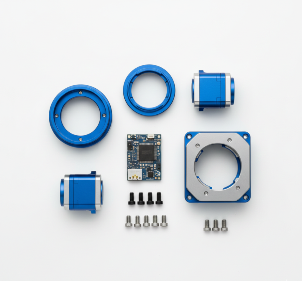

However, consolidation must be balanced against manufacturability; combining parts should not result in a component that is impossibly complex or expensive to manufacture.
To identify candidates for elimination or integration, engineers should ask three fundamental questions for each part:
- Relative Motion: Does this part need to move relative to other parts? (e.g., a steering wheel).
- Material Necessity: Does this part require a different material than its neighbor to function? (e.g., a rubber seal on a steel housing).
- Serviceability: Does this part need to be removed for assembly or maintenance?
If the answer to all three is “no,” the part is a prime candidate for integration into a neighboring component.
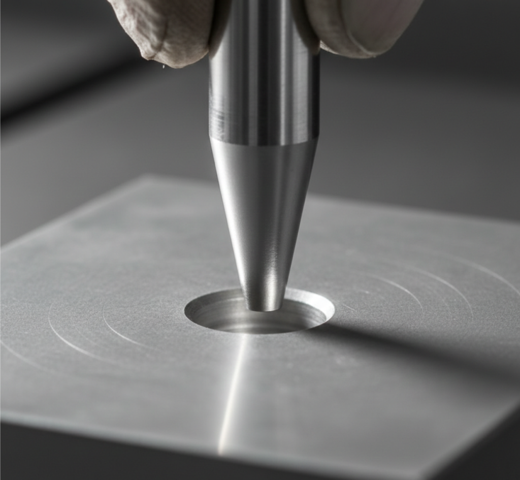
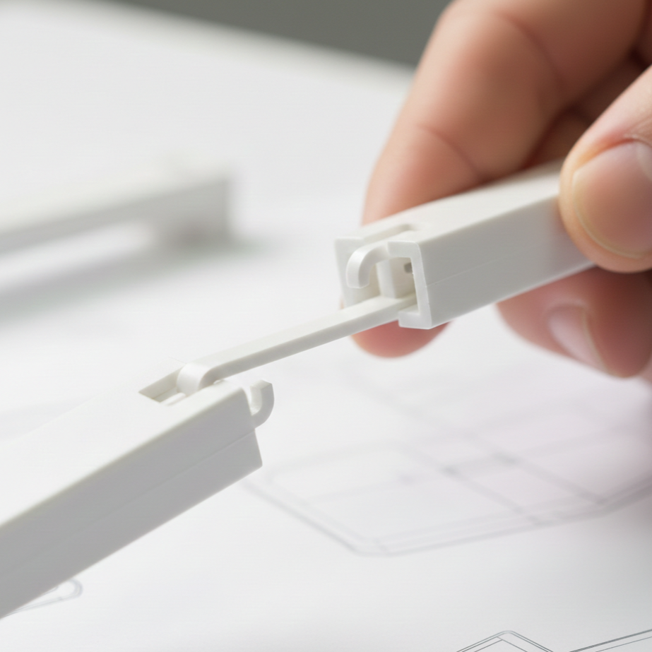
2. Self-Locating and Self-Orienting Features
DfA aims to remove the need for precision manual alignment. Self-locating parts use geometry to guide themselves into the correct position without additional fixtures or alignment tools.
Common features include:
- Chamfers and Countersinks: Tapered edges on pins or holes that guide insertion even when slightly misaligned.
- Bosses and Slots: Mating features that physically restrict movement to the intended position.
In the example below, where two parts are fixed for the next step of welding, the upper part is symmetrical. If it wasn’t, the taps should also be of different lengths to create a self-orienting feature that allows assembly in a single, correct orientation only.
3. Built-In Fasteners
Threaded fasteners (screws, nuts, bolts) are notorious for increasing assembly time and defect rates. They often require washers, tools, and specific torque settings.
Where possible, DfA encourages replacing separate fasteners with integral features:
- Snap-Fits: Allow parts to be joined in a single linear motion. Types of snap fit connections include cantilever, torsion, and annular snaps.
- Adhesives & Welding: For permanent assemblies, ultrasonic welding or bonding eliminates hardware entirely.
Note: Integral fasteners are not a universal solution. Screws are still preferred for high-load applications or assemblies requiring frequent non-destructive disassembly.
Fastener Selection Table
| Joining Method | Assembly Speed | Disassembly | Cost Impact | DfA Rating |
| Threaded Fasteners (Screws/Bolts) | Slow (High labor) | Easy (Non-destructive) | High (Requires hardware inventory) | ⭐ |
| Snap-Fits (Plastic/Metal) | Fast (One motion) | Difficult (Can be designed for it) | Low (Free with part) | ⭐⭐⭐ |
| Adhesives / Welding | Medium (Cure time) | Impossible (Destructive) | Low/Medium (Consumables) | ⭐⭐ |
| Rivets | Fast | Difficult (Drill out) | Low | ⭐⭐ |
4. Part Symmetry and Asymmetry
Symmetric designs allow parts to be used in multiple orientations and to fit in multiple ways. This design reduces the opportunity for misalignments and the time for reorientation or to figure out the correct alignment.
Symmetrical parts allow the use of the same tools during assembly, further reducing the cost of multiple or special tools.
If a symmetrical design would compromise the product’s function, the first alternative is to incorporate self-orientation features. However, if this is also not feasible, the asymmetry must be clearly indicated.
This is typically achieved through visual cues like markings, labels, and variations in color, shape, and/or texture. These cues serve to highlight the asymmetry, ensuring the part is correctly oriented and thereby preventing assembly errors caused by confusion.
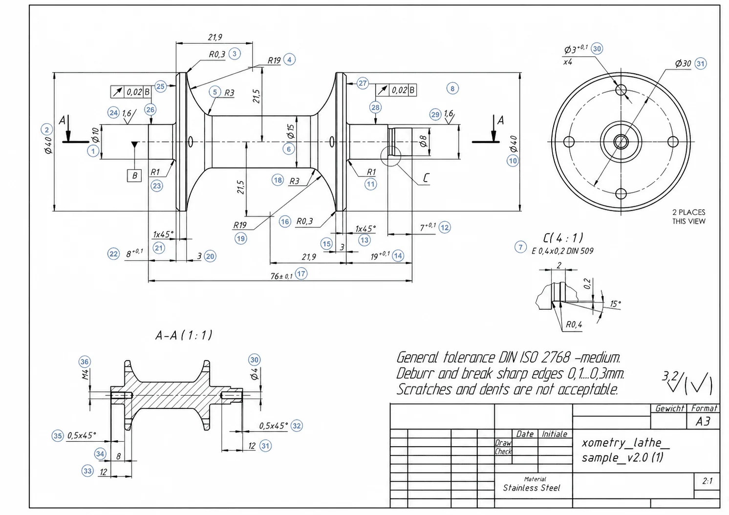
5. Reasonable Tolerances
Currently, extremely fine tolerances in manufacturing are possible using modern mechanical engineering tools. However, obtaining precise tolerances is time-consuming and expensive, and unnecessarily tight fits lengthen the assembly time.
DfA advocates for the loosest possible tolerance that still preserves function.
DfA also incorporates tolerance stacking analysis. This process examines how the overall final tolerance is influenced by the accumulated tolerances of the individual components. Methods for conducting tolerance stacking analysis include worst-case tolerance analysis and statistical tolerance analysis.
Tolerance stacking analysis is carried out during DfA to ensure that the tolerance sum (both upper and lower extremes) remains within the tolerance range allowed for assembly. For example, if the tolerance sum is smaller than the specified range, a gap will occur between the joining parts.
6. Modular Design
For complex products, DfA advocates breaking the design into distinct sub-assemblies or modules.
- Modules can be assembled and tested simultaneously on different lines with parallel production, drastically reducing final assembly time.
- Standard modules (e.g., a power supply unit) can be reused across different product lines, creating economies of scale.
7. Standardization
Another key objective of DfA is to use common tools, parts and interfaces across the entire assembly and product line.
Using standard, commercially available components minimizes inventory complexity and tooling costs.
- Design the entire product to use the same screw head size to prevent tool changes.
- Use the same screw length throughout the assembly to prevent operators from installing a “short” screw in a “deep” hole.
In essence, it’s about turning assembly into a repeatable, predictable operation rather than a problem-solving task.
8. Top-Down Assembly
Top-down, or vertical, assembly is a recommended Design for Assembly (DfA) practice because gravity assists the process.

This simplifies manual assembly by reducing the need for fixturing, reorientation, and holding, allowing the product to remain stable. It also benefits automated lines by improving reliability, reducing tooling complexity, and ensuring consistent cycle times.
The main advantage is minimizing handling, orientation changes, and overall complexity.
9. Ease of Handling
If a part is difficult to pick up, it slows down the line. DfA considers the physical handling of every component:
- “Open” parts like C-clips or open-ended springs tend to nest and tangle in bins. Designing them with closed loops prevents this.
- Parts that are too small, slippery, or sharp require tweezers or gloves, adding time to every cycle.
Furthermore, easy-to-handle parts facilitate automated assembly.
10. Mistake-Proofing (Poka-Yoke)
DfA incorporates Poka-Yoke (error-proofing) principles to make incorrect assembly physically impossible.
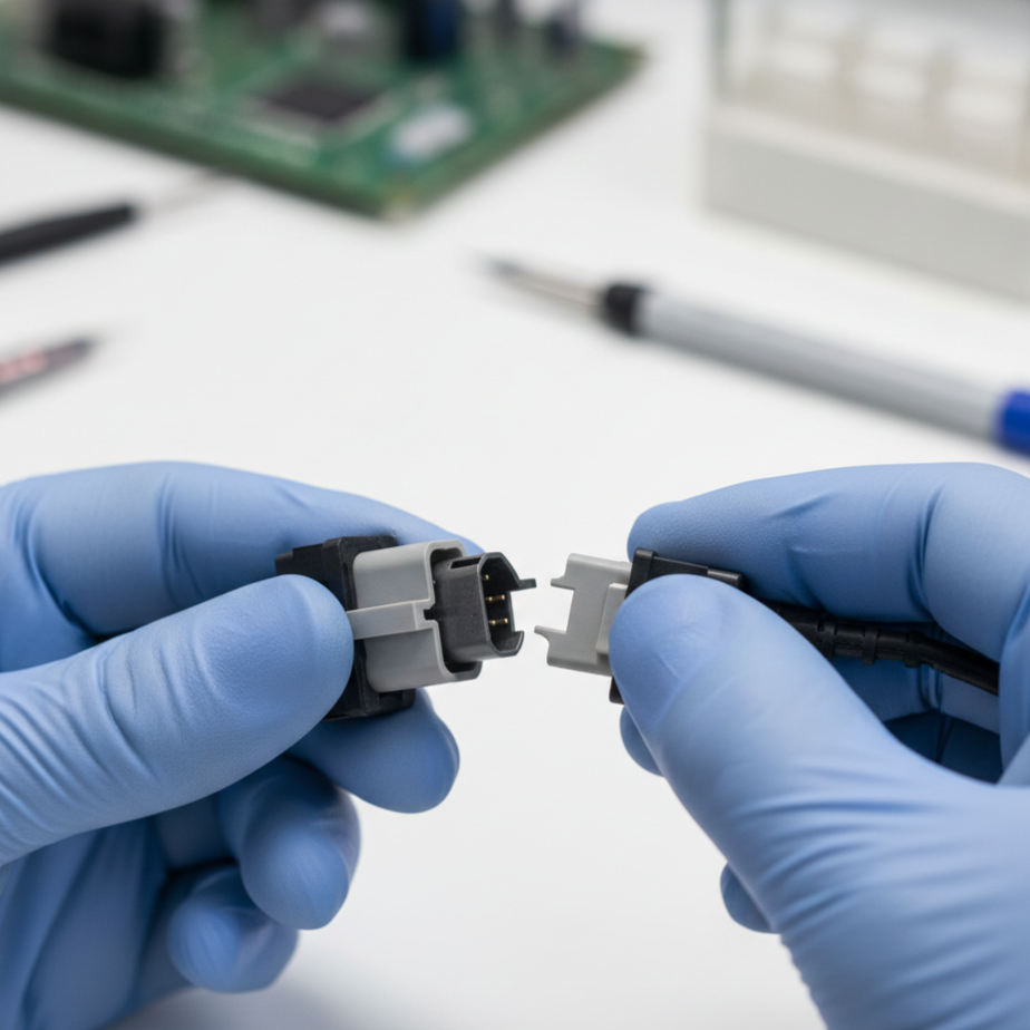
- Physical Keys: Designing connectors (like USB plugs or battery compartments) that physically fit only one way.
- Interference Features: Adding tabs or blocks that prevent a part from seating if it is upside down.
- Visual Cues: Using color-coding or alignment marks to guide operators.
- Incorporating fail-safe mechanisms to stop assembly when a part is incorrectly positioned or oriented
- Fail-Safe Mechanisms: Systems that automatically halt the assembly process if a part’s positioning or orientation is wrong.
Benefits of Design for Assembly
Implementing the DfA methodology offers significant advantages across the entire product lifecycle, from the factory floor to the end-user.
| Core Benefit | The Bottom Line |
| Cost Reduction | Drastically cuts labor, tooling, scrap, and overhead expenses by minimizing part counts. |
| Efficient Manufacturing | Reduces assembly errors and boosts First Pass Yield (FPY). |
| Enhanced Supply Chain | Consolidates part varieties, leading to fewer suppliers and simpler logistics. |
| Faster Production | Shortens cycle times and increases overall line throughput. |
| Automation Readiness | Optimizes part geometries to easily accommodate robotic gripping and automated assembly lines. |
| Simple Maintenance | Facilitates easier disassembly for post-purchase repairs and service. |
| Quality & Reliability | Lowers long-term defect rates by minimizing potential points of failure. |
| Sustainability | Uses less energy and material, and seamlessly aligns with Design for Disassembly (recycling) principles. |
Cost Reduction
Cost reduction is the most tangible benefit of DfA. By minimizing part counts and simplifying operations, expenses are cut across several categories:
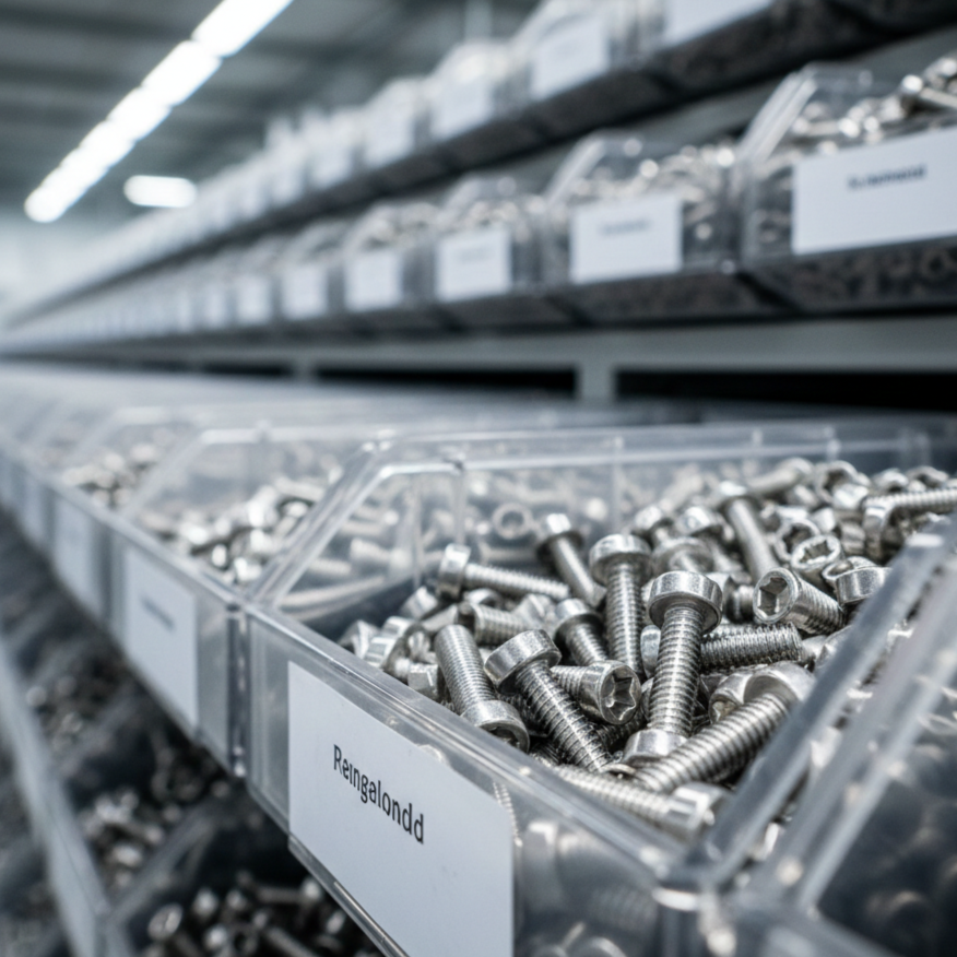
- Labor: Simpler assemblies require fewer man-hours and less operator training.
- Inventory: Standardization significantly reduces the variety of parts kept in stock. For example, limiting fasteners to only M6x10 and M6x20 bolts reduces the number of bins, tools, and SKUs required.
- Tooling: Eliminating specialized components reduces the need for expensive custom jigs, fixtures, and tools.
- Scrap & Waste: Fewer parts and simpler connections reduce the likelihood of assembly errors that lead to scrapped materials or redesigns.
- Overhead: Faster, smoother assembly lines reduce indirect costs such as utilities and supervision.
Simple and Efficient Manufacturing
DfA naturally streamlines the manufacturing process. With fewer components to handle and standardized interfaces to connect, the opportunities for assembly errors are drastically reduced. This leads to higher “First Pass Yield” (FPY), which means the percentage of products that pass inspection without needing rework.
Enhanced Supply Chain
A DfA-optimized product with standardized components relies on fewer unique parts, which often means fewer suppliers. This consolidation simplifies communication, reduces logistics complexity, and shortens the overall supply chain.
While reducing the supplier base simplifies logistics, engineers must still ensure they are not reliant on a single source for critical components to avoid supply chain “singularity.”
Faster Production Times
Every part eliminated is a step removed from the assembly line. DfA directly reduces cycle times, increasing production throughput. This speed allows manufacturers to be more flexible and respond faster to market demand fluctuations.
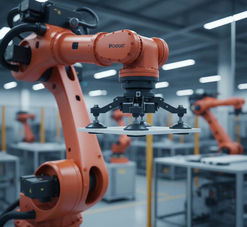
Mass Production and Automated Assemblies
In addition to optimal part manufacturing, simplifying the assembly process and increasing its speed are key requirements for mass production.
Simplified assembly facilitates automation, often utilizing robotic systems with tools like vacuum cups or three-finger grippers. This requires designing the product to accommodate the equipment, which includes specific features such as smooth surfaces necessary for suction.
However, high-volume production does not strictly require automation. Applying Design for Assembly (DfA) principles can ensure efficient mass production even when assembly is primarily manual.
In practice, many contemporary products adopt a hybrid approach, applying automation selectively. For example, in consumer electronics, appliances, and automotive subassemblies, the final assembly (and sometimes intermediate steps) are frequently manual. This allows for greater flexibility, better management of variations, and enhanced quality control.

Simple Maintenance
Many of the principles that guide toward simple assembly are also present in the Design for Maintenance framework. This is critical for making maintenance easy. Just the ability to disassemble is the first step, closely followed by the ease of it.
High Quality and Reliability
Products with simpler assemblies show lower defect rates as fewer mistakes occur during manufacturing. In addition, these products show higher reliability over the product lifetime owing to their lower defects and fewer chances for malfunction due to failed fasteners and connections.
Sustainability Benefits
Fewer parts mean less material usage and less energy consumed during manufacturing. Additionally, DfA often aligns with Design for Disassembly, making products easier to take apart for recycling at the end of their service life.
Implementing Design for Assembly
Effective implementation of DfA should follow a structured procedure, comprising the following steps:
1. Early Integration of DfA
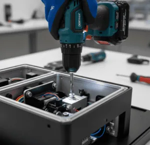
DfA is most effective when applied during the conceptual design phase. Integrating assembly considerations early through collaboration between design, engineering, and production teams prevents costly redesigns later. It is far cheaper to erase a line on a CAD drawing than to retool a production line.
2. Conducting DfA Analysis (Boothroyd-Dewhurst Method)
Engineers often use established methodologies to quantify assembly efficiency. The Boothroyd-Dewhurst method is the industry standard, focusing on three key analyses:
- Part Necessity: Can this part be eliminated based on the three fundamental DfA questions (Relative motion? Material difference? Service necessity?)?
- Handling Analysis: How much time is required to grasp, orient, and move the part?
- Insertion Analysis: How much time is required to insert and secure the part?
The goal is to calculate the DfA Index (Efficiency):
DfA Efficiency = (Minimum Theoretical Parts × 3 seconds) / Total Estimated Assembly Time
(Note: 3 seconds is the theoretical ideal time to handle and insert a standard part).
This process is aided by Design for Assembly software, such as DFA Product Simplification Software, which quantifies the assembly efficiency and suggests which parts should be consolidated.
3. Constructing Assembly Flow Diagrams
Design teams create flow diagrams to map the entire assembly sequence. These diagrams act as a visual manual, highlighting potential bottlenecks, difficult orientations, or steps where access is restricted. Identifying these “tricky points” on paper allows for correction before prototyping.
4. Prototyping and Testing
Physical testing is essential and must be conducted. Prototypes need to be assembled under realistic conditions, using either actual line workers or robotic systems. This practical step is crucial because it frequently uncovers real-world problems (like hand fatigue or insufficient tool clearance) that standard CAD simulations cannot predict.
5. Automated vs. Manual Assembly
DfA helps determine the optimal assembly mode based on volume and complexity.

- Automated assembly in small-scale production can be expensive due to the need for design modifications, specialized equipment, and extensive worker training.
- The complexity of the assembly process (manual, automated, or hybrid) must be assessed to find the option with the lowest intricacy.
- Automated assembly generally reduces errors but offers less adaptability and responsiveness to changes compared to manual assembly.
- Due to the limited range of motion of robotic arms, design specifications and tooling must be precisely tailored to match the specific operational capabilities of the robots.
6. Iterative Refinement
DfA is not a one-time step; it is a cycle. After testing and cost analysis, the design is refined, and the DfA index is recalculated. This loop continues until the technical performance and production cost targets are met.

How DfA Relates to Other DfX Methods?
Design for Assembly (DfA) does not exist in a vacuum. It is a central pillar of the Design for X (DfX) framework, acting as the bridge between component creation and product lifecycle management.
- DfA vs. Design for Maintenance (DfMS): DfA is heavily focused on putting a product together, whereas Design for Maintenance & Serviceability focuses on taking it apart. However, the principles often overlap. A modular design that uses snap-fits for easy assembly often makes component replacement (maintenance) faster, provided the fasteners are non-destructive.
- Design for Supply Chain: DfA’s emphasis on standardization directly simplifies procurement and reduces inventory risks.
- Design for Inspection: By simplifying the product structure and ensuring line-of-sight access to connections, DfA naturally creates accessible test points for Quality Control.
Common Mistakes in Design for Assembly
Even experienced engineers can fall into traps when optimizing for assembly. Avoid these common pitfalls to ensure successful implementation.

Over-Consolidation
While reducing part count is a primary goal, merging too many functions into a single complex part can backfire. If a consolidated part becomes too difficult to mold or machine, the DfM costs may outweigh the DfA savings.
Ignoring the Assembly Line
Designing in a CAD vacuum without consulting assembly technicians is a critical error. Features that look easy to assemble on a screen (like blind screw insertions) can be a nightmare on the factory floor.
Sole Focus on Speed
Optimizing purely for assembly speed (e.g., using cheap adhesives) can compromise other DfX goals, such as durability or serviceability. DfA must be balanced against the product’s functional requirements.
Neglecting Tolerance Stacks
A common mistake is assuming parts will always be at their nominal size. Failing to account for tolerance stack-up in a complex assembly can lead to interference issues that halt production.
The Serviceability vs. Integration Trade-Off
DfA promotes “Integration” (combining parts), but this can conflict with Design for Maintenance. Engineers must weigh assembly speed against repairability.
- Ultrasonic Welding: A DfA ideal. Zero fasteners, instant bond, low cost. Downside: Impossible to repair non-destructively.
- Traditional Hardware: While separate hardware like screws are the maintenance standard for easy upgrades and repairs, they come with the downside of significantly slower assembly times.
The decision relies on product strategy: is this a low-cost “consumable” suitable for welding, or a high-value asset where repairability is non-negotiable?

Real-World Examples
These examples illustrate how DfA principles have transformed entire industries.
The IBM Proprinter
In the 1980s, IBM initially planned a highly automated, capital-intensive factory for its new printer. However, after applying DfA analysis, they realized the design itself was the bottleneck.
By redesigning the printer to snap together in layers (Top-Down Assembly) without screws or springs, they achieved a design so simple that a human could assemble it in 3 minutes.
This eliminated the need for complex robots entirely, proving that simplification often beats automation.
The Sony Walkman
Sony’s dominance in the portable audio market was largely due to a “Platform Strategy” rooted in DfA. By designing a shared internal mechanism (module) that was optimized for vertical automated assembly,
Sony could release hundreds of different Walkman models with unique outer shells while using the same efficient core. This allowed them to scale production rapidly, dominate the market for decades and generate huge revenues for the Walkman, exceeding $1 billion.
Mastering the Assembly Mindset
Design for Assembly (DfA) is a critical strategy that integrates assembly considerations into the early design phase. As an influential DfX strategy, DfA significantly lowers product cost, improves quality, and boosts profitability and customer satisfaction.
DfA simplifies future automation, disposal, and recycling. While this text focuses solely on DfA, combining it with Design for Manufacturing (DfM) is highly recommended, as DfA and DfM together offer the most impactful decisions for comprehensive manufacturing.


Comment(0)