 Europe
  Türkiye
While modern manufacturing relies heavily on 3D CAD models, the 2D technical drawing is still crucial for specifying critical tolerances, surface finishes, and inspection needs that 3D models cannot fully convey.
This guide covers the fundamental elements of engineering (technical) drawings—from line types and orthographic projections to dimensioning and information blocks—and provides a step-by-step process for preparing flawless technical drawings for production.

Why Are Technical Drawings Important?
In an era where instant quoting engines and CNC machines can interpret 3D CAD files directly, the role of the 2D drawing is often questioned. However, for almost all professional manufacturing jobs, a 3D model is not enough.
A 3D CAD file defines the perfect geometry, but the 2D technical drawing defines the allowable imperfections.
Main Functions of an Engineering Drawing:
- Clear specifications for internal/external threads, knurling, and surface treatments that are not explicitly modeled in 3D.
- A 3D model has nominal dimensions. The drawing uses GD&T and dimensional tolerances to tell the machinist which features are critical for function and assembly.
- Specifying surface roughness values (e.g., Ra 0.8 µm) for specific surfaces, which directly impacts machining time and cost.
- In the event of a dispute regarding parts that do not fit or function, the signed engineering drawing is the definitive document for resolving the issue.
- A clear drawing allows estimators to quickly identify tight tolerances, complex features, and finishing requirements that drive up cost.
Even for simple parts, always accompany your 3D model with a 2D technical drawing. The 3D file drives the machine’s toolpath, but the 2D drawing is the inspection document used for quality control.
The Components of an Engineering Drawing
A first glance at an engineering drawing can be daunting due to the density of information. However, decoding it starts with understanding its fundamental building blocks: lines, views, coordinates, and information blocks.
It is important to note that this article discusses drawings from a modern, CAD-first perspective. While traditional manual drafting relied strictly on variations in line thickness (e.g., thick for visible outlines, thin for dimensions), CAD software often automates line weights or uses color coding for differentiation. However, the fundamental types of lines and their meanings remain standardized.
Lines
Lines are the most basic element of any technical drawing. Each type of line conveys a specific meaning about the part’s geometry or the drawing’s annotations.


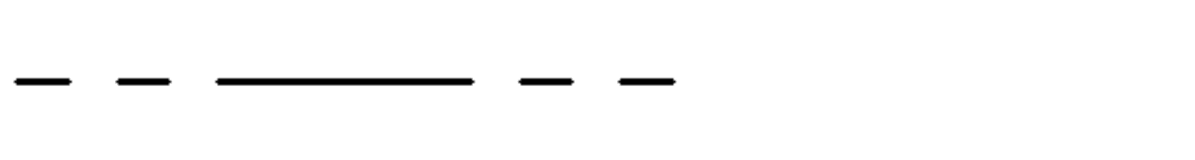
Visible Line (Continuous): Thick, solid, continuous lines define the visible edges and contours of the part as seen from the specific angle of view. These represent the physical boundaries of the object.
Hidden Line (Dashed): Thin lines composed of short dashes represent edges, surfaces, or features hidden behind other geometry in the current view.

Phantom Line: Thin lines that alternate one long dash with two short dashes. They depict alternate positions of moving parts, adjacent components for context, or repeated features. For example, solid lines might show a hinge in the closed position, while phantom lines indicate its open position path.
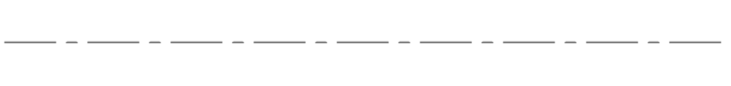

Center Line: Thin lines alternating long and short dashes indicate the center axis of cylindrical features (like holes or shafts) or define lines of symmetry on the part.
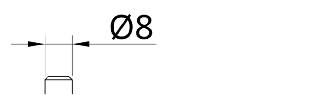

Dimension and Extension Lines: These thin, solid lines work together to define a measurement.
Extension lines stretch outward from the feature’s boundaries to show the extent of measurement.
The dimension line runs between them, usually terminated by arrowheads, with the measurement value placed centrally above or within it.
Leader Line: A thin line terminating in an arrowhead or dot, used to connect a specific feature to a note, dimension, specification, or GD&T callout.
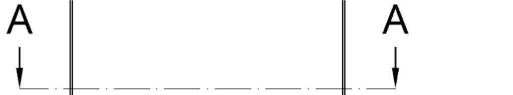

Cutting Plane Line: A thick or broken line terminated with large arrows at the ends. It indicates the path and viewing direction of the cut used to create a section view. It is always accompanied by letter designations (e.g., A-A) for reference.
Section Line (Hatching): Thin, angled lines arranged in patterns to indicate solid material that has been cut through in a section view. Different standard hatch patterns are often used to visually differentiate between materials or adjacent parts in an assembly.
The cross hatching feature simply illustrates an area of the part that was cut for the cross sectional view. For clarity, different materials use dedicated hatch patterns and mating parts of the same material usually have a different angle for hatching.
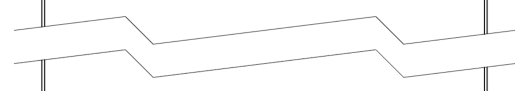
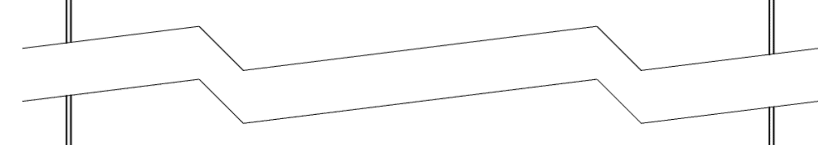
Break Line: Zig-zag or freehand wavy lines used to shorten the view of a long, uniform part that would otherwise not fit the drawing sheet at the required scale. It indicates that a section of the part has been omitted for brevity. To distinguish between break lines and section lines, compare the broken view and cross-section view, which are presented further down.
Coordinates
Coordinates are a grid system placed along the borders of large or complex technical drawings. They serve as alphanumeric reference points, making it easy to locate specific areas when discussing the drawing with manufacturers or colleagues.
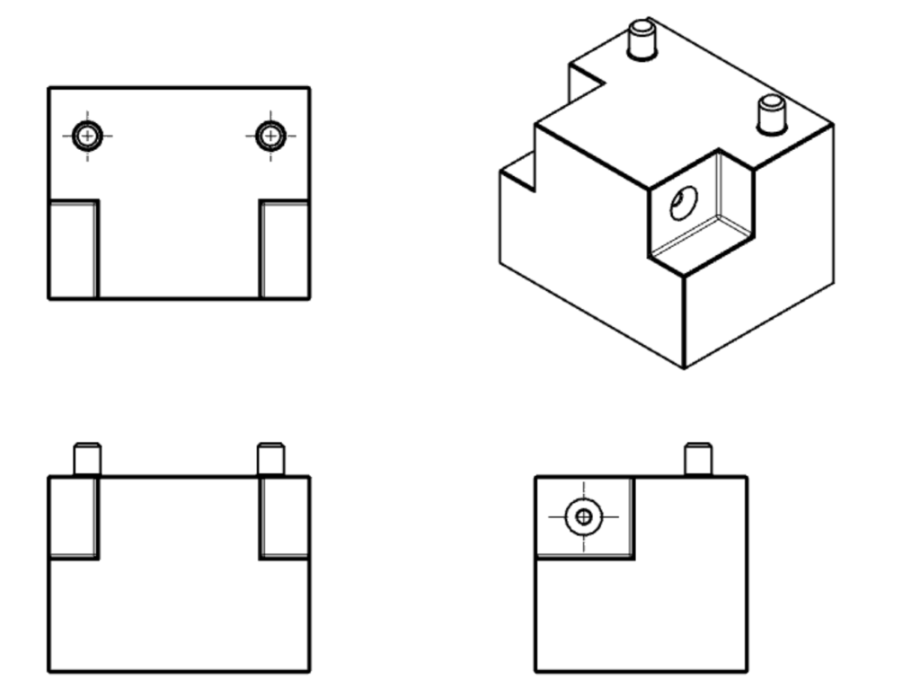
Primary Views (Orthographic Projection)
Orthographic projection is the standard method for representing a 3D object in 2D without distortion. A multiview drawing typically includes three primary views: front, top, and side. Because there is no perspective distortion, every line can be measured directly to determine the true 1:1 dimension (or scaled dimension, e.g. 1:5).
- Front View: The most descriptive face of the part, usually chosen as the central view.
- Top View: Shows the object viewed directly from above.
- Side View: Shows the depth of the part viewed from the left or right.
The arrangement of these views depends on the regional standard:
First Angle Projection (Europe/Asia): The part is imagined as resting on the paper, and you flip it over to see the other sides. The front view is typically in the upper-left.

Third Angle Projection (USA/Canada): The part is imagined inside a glass box, and the views are projected onto the box walls. The top view is placed directly above the front view, and the right-side view is placed to the right of the front view.
- Check the Symbol: Always check the projection symbol in the title block to confirm whether the drawing uses First or Third Angle projection, as misinterpretation can lead to manufacturing parts backwards.
Supporting Views

While orthographic views are primary, complex parts often require additional view types for clarity.
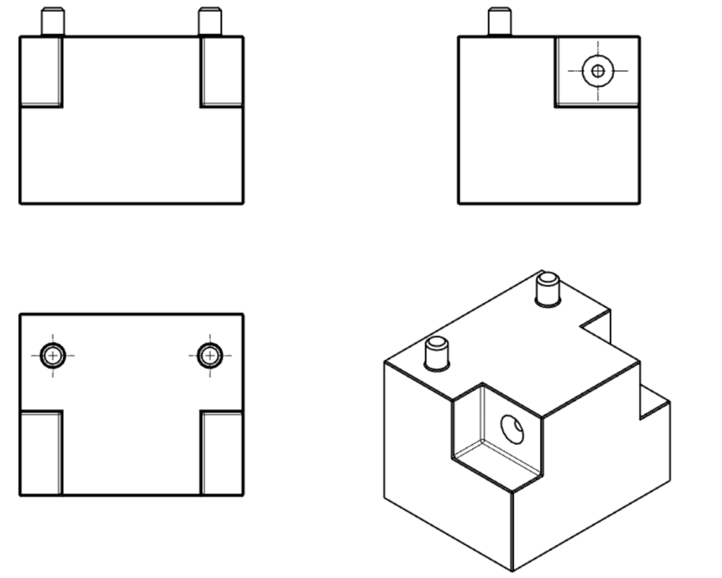
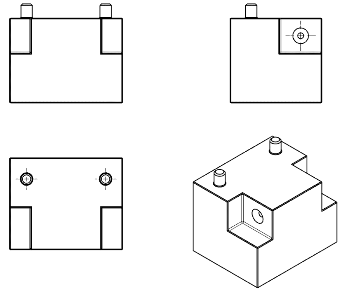
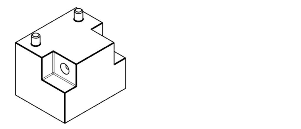
Isometric View: A 3D pictorial representation of the part. While not strictly necessary for manufacturing geometry, including an isometric view is highly recommended. It gives the machinist an immediate, intuitive understanding of the part’s overall shape, installation direction, and build orientation.

Section View (Cross Section): A section view cuts through the part to reveal internal features not visible in orthographic views.
- How it works: A labeled cutting plane line on an orthographic view shows where the cut is made. The resulting section view uses cross-hatching patterns to indicate areas where solid material has been cut away. Complex parts may require multiple section views.

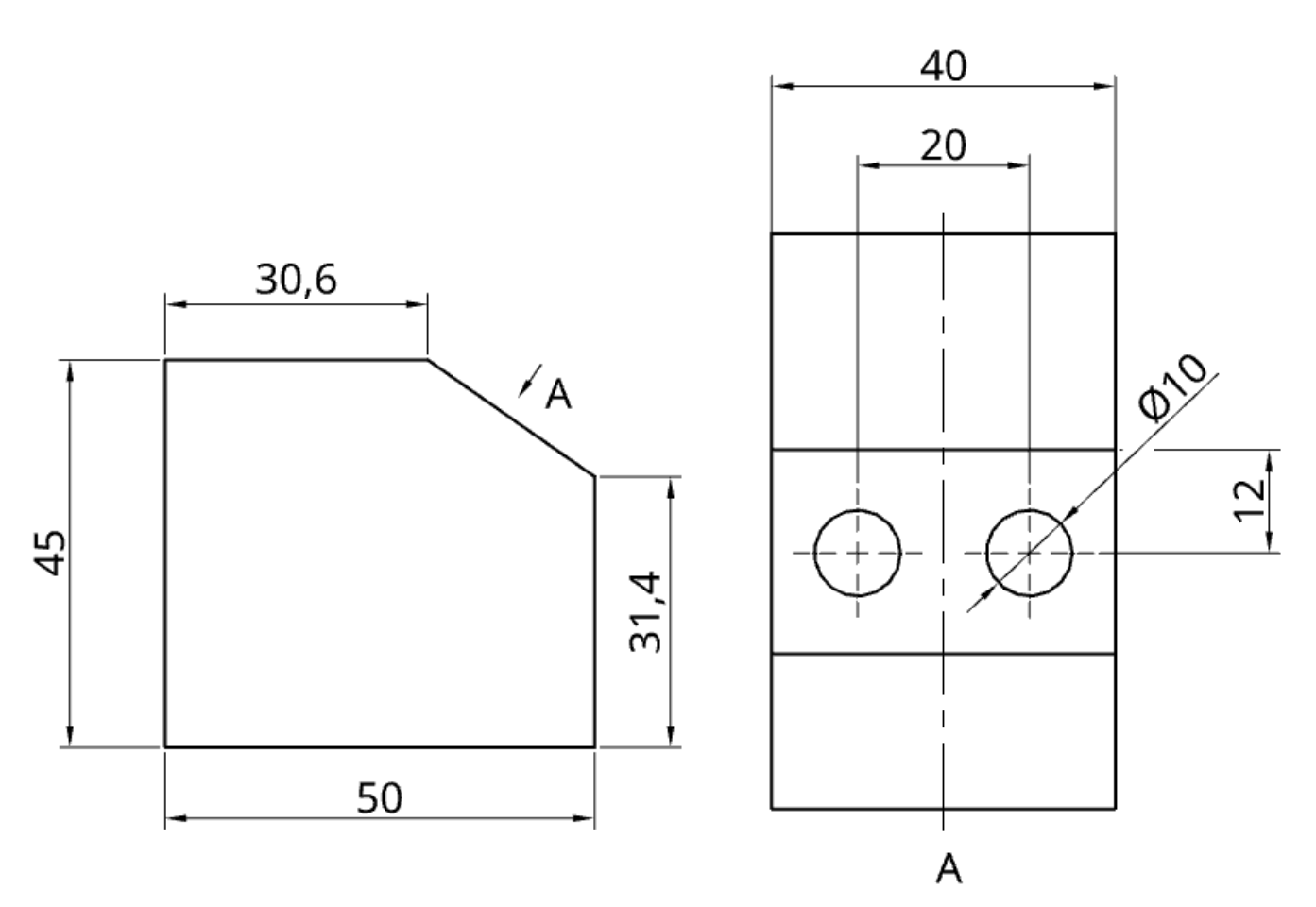
Auxiliary View: An auxiliary view shows a face of the part from an angle that is not parallel to the standard primary planes (front, top, side). This is essential for showing the true dimensions and shape of inclined or oblique surfaces.


Detail View: A detail view is a magnified “zoom-in” on a specific, complex area of another view. It is used when features are too small or crowded to dimension clearly at the main drawing scale. Detail views do not need to be aligned with the orthographic views. They are identified by a single letter that corresponds to the area on another view being magnified.
Specialized Views
Beyond the standard projections, certain views are used to simplify complex drawings or clarify assembly instructions.

Broken View A broken view is used for long, uniform parts (like shafts, beams, or pipes) that do not fit on a standard drawing sheet at the required scale. Break lines are used to “remove” the central, unchanging section, allowing the critical ends to be shown in detail without wasting space.

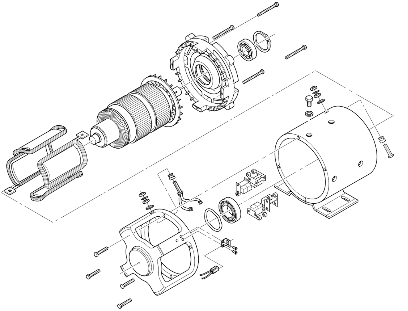
Exploded View Used primarily in assembly drawings, an exploded view shows all components of an assembly separated but aligned in their proper assembly order. This provides a clear visual guide for how the parts fit together, significantly aiding the assembly and maintenance processes.
Dimensions & Tolerances
A drawing with only views is just a picture. Dimensions and tolerances convert that picture into a manufacturable specification.
Dimensions: Specify the exact size, location, and orientation of every feature on the part. A complete dimension consists of:
- Extension Lines: Showing the boundaries of the feature being measured.
- Dimension Line: Running between the extension lines, usually with arrowheads.
- Dimension Value: The numerical value indicating the measurement (e.g., 50 mm).
Every feature needed for manufacturing—from overall part size to the location of every hole and slot—must be clearly dimensioned.
Tolerances: No manufacturing process is perfect. Therefore, every dimension must have a tolerance that defines the acceptable range of variation. A nominal dimension without a tolerance is incomplete.
Tolerances tell the manufacturer how much a part can deviate from the nominal size and still function correctly.
- Example: A hole dimensioned as 10 mm ±0.1 mm means the final hole diameter can be anywhere between 9.9 mm and 10.1 mm.
Types of Tolerances:
- General Tolerances: A standard tolerance class (e.g., ISO 2768-m) is usually specified in the title block, applying to all dimensions that do not have a specific tolerance callout.
- Specific Tolerances: Tighter tolerances applied directly to critical features that require greater precision for fit or function.
- Geometric Dimensioning & Tolerancing (GD&T): A symbolic language used to define the allowable variation in form, orientation, and location of features, providing more control than simple dimensional tolerances.
DFM Tip: The Cost of Precision
Apply tight tolerances only where absolutely necessary for part function or assembly. Overly tight tolerances (<±0.05 mm) significantly increase manufacturing time, inspection efforts, and scrap rates, leading to unnecessarily high production costs.
Information Blocks
A drawing is more than just geometry and dimensions. The information blocks located along the borders provide the essential administrative, technical, and instructional context required for manufacturing and assembly.


1. The Title Block
Located in the bottom-right corner, the title block is the drawing’s identity card. It contains all the fundamental information needed to identify, file, and interpret the document. While content can vary by company standard, it typically includes two categories of data.
Standard Title Block Contents (Engineer Table)
| Category | Typical Information Included |
| Administrative Data | Drawing Title/Part Name, Drawing Number, Revision Level, Company Name, Author (Drafter), Checker, Approval Date. |
| Technical Data | Scale (e.g., 1:2), Projection Angle Symbol (First vs. Third), Unit of Measure (mm or inch), Material Material (e.g., Al 6061-T6), General Tolerances, Sheet Size. |


2. The Notes Block (Notes to Manufacturer)
Usually located in the bottom-left corner or directly above the title block, this section contains critical instructions that apply to the entire part but aren’t tied to a specific feature’s dimension.
DFM Tip: Standard Drawing Notes Including standard notes ensures consistent quality without cluttering the views. Common examples include:
- “ALL DIMENSIONS ARE IN MILLIMETERS.”
- “REMOVE ALL BURRS AND SHARP EDGES.”
- “SURFACE FINISH UNLESS OTHERWISE SPECIFIED: Ra 3.2.”
- “INTERPRET DRAWING PER ASME Y14.5-2018.”
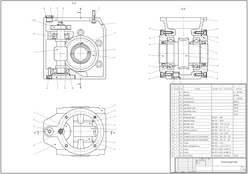
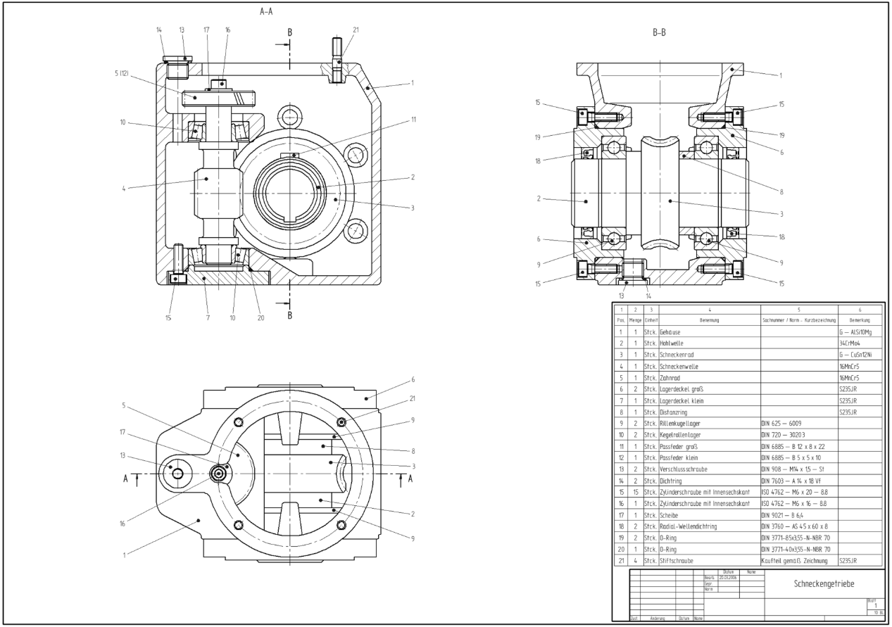
3. Bill of Materials (BOM)
Used exclusively on assembly drawings, the BOM is a structured list located just above the title block. It itemizes every component required to build the assembly, serving as the primary reference for purchasing and assembly teams.
A standard BOM typically includes columns for:
- Item Number (matching balloons on the drawing view)
- Part Number
- Part Description
- Quantity (QTY) per Assembly
- Material
Types of Engineering Drawings
While there are various specialized drawing types, most manufacturing documentation falls into one of two primary categories: part drawings and assembly drawings. Understanding the distinct purpose of each is critical for effective communication.
1. Part Drawing (Detail Drawing)
A part drawing is the definitive manufacturing specification for a single, individual component. Its purpose is to provide every piece of information required to manufacture that one part from raw material to finished product, without ambiguity. It is all about precision and completeness.
A complete part drawing must include:
- Multi-view Orthographic Projections to define geometry.
- Full Dimensions and Tolerances for every feature.
- Material and Finish Specifications (e.g., Al 6061-T6, Anodize Black).
- All necessary supporting views (sections, details) to clarify internal or complex features.
2. Assembly Drawing
An assembly drawing shows how multiple individual parts fit together to form a complete product or sub-assembly. Its primary purpose is to guide the assembly and maintenance processes, not manufacturing.
An assembly drawing typically typically includes:
- Exploded or Sectioned Views showing part relationships and orientation.
- Balloons (Item Numbers) pointing to each component, corresponding to the BOM.
- Bill of Materials (BOM) listing all parts and quantities.
- Overall Reference Dimensions (e.g., total length, width, height) but no detailed manufacturing dimensions for individual parts.
| Feature | Part Drawing | Assembly Drawing |
| Primary Purpose | Manufacturing of a single component. | Assembly of multiple components. |
| Level of Detail | High: Every feature fully dimensioned and toleranced. | Low: Only overall dimensions and part identification (balloons). |
| Key Components | Orthographic views, full dimensions, material spec, finish spec. | Exploded/section views, BOM, balloons, reference dimensions. |
| Target Audience | Machinist, fabricator, quality inspector. | Assembler, manufacturing engineer, maintenance technician. |
10 Steps to Prepare a Perfect Engineering Drawing
Modern manufacturing begins with a 3D CAD model, and most CAD software includes powerful tools to generate 2D drawings directly from that model. This process eliminates the need to draw views from scratch, allowing you to focus on adding critical manufacturing information.
Before you begin, ensure you have chosen a capable CAD program that suits your needs, whether it’s a professional suite like SolidWorks or Fusion 360, or a capable free tool like Onshape or FreeCAD.
Here is a step-by-step guide to creating a production-ready engineering drawing.
Step 1: Select Your Template
Start with a standard template (e.g., ISO, ASME, or a company-specific one). This ensures your drawing has the correct sheet size, border, coordinate system, and a pre-formatted title block ready to be filled.
Step 2: Place Your Primary Orthographic Views
Drag and drop your front, top, and side views onto the drawing sheet.
- Leave ample white space between views for dimensions and notes. Avoid overcrowding.
- Ensure the views are arranged according to the correct projection angle (First or Third) specified in your title block.
Step 3: Add Section and Detail Views
Identify features that are not clearly defined in the primary views.
- Section Views: Use them to reveal internal features like holes, chambers, or complex profiles.
- Detail Views: Use them to magnify small, intricate areas that are difficult to dimension at the main scale.
Step 4: Add an Isometric View
While not strictly necessary for geometry, always include an isometric view if space permits. It provides an immediate, intuitive visual reference for the machinist, reducing the risk of misinterpretation.
Step 5: Place Center Lines and Center Marks
Use your CAD software’s automated tools to place center lines on all cylindrical features (holes, shafts) and lines of symmetry.
- Action: Always double-check the automated placement to ensure nothing was missed.
Step 6: Add Dimensions to Your Drawing
This is the most critical step. Dimensions define the geometry that must be manufactured.
Dimensioning Best Practices (Engineer Table)
| Best Practice | Why It Matters |
| Establish a Baseline | Select common datums (edges or center lines) and dimension features from them. |
| Don’t Duplicate | Dimension a feature only once, on the view that describes it best. |
| Group Dimensions | Keep related dimensions together (e.g., all dimensions for a specific feature on the same view). |
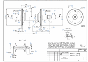
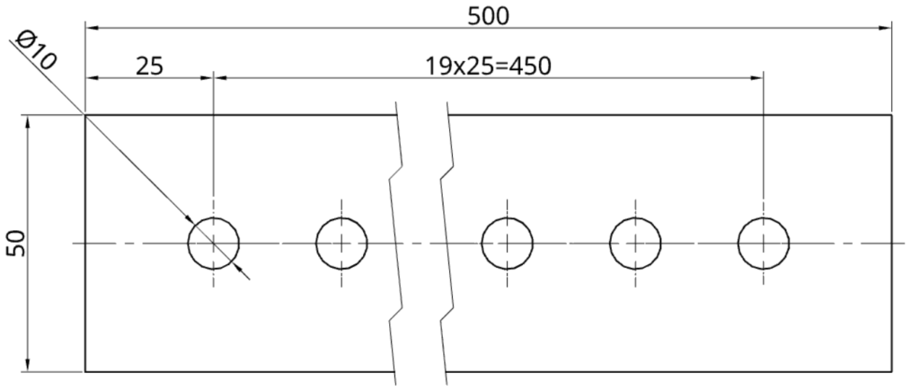
| Use Quantity Symbols | For identical features, dimension one and indicate the quantity (e.g., 3 x ∅2.0 ). |
Step 7: Specify Holes and Threads
Clearly define the location, size, and type of all holes and threads.
Standardize your holes whenever possible, design with standard drill bit and thread sizes. This eliminates the need for custom tooling, significantly reducing manufacturing cost and lead time.
Use callouts to specify complex hole features compactly. A typical callout includes:
- Hole Diameter
- Hole Depth
- Thread Specification (if applicable)
- Counterbore/Countersink dimensions
- Quantity

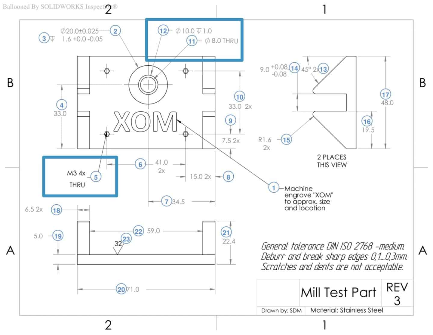
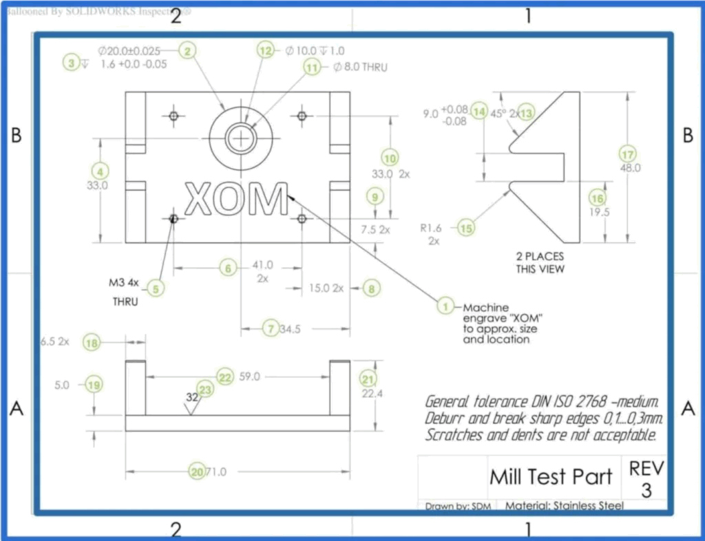
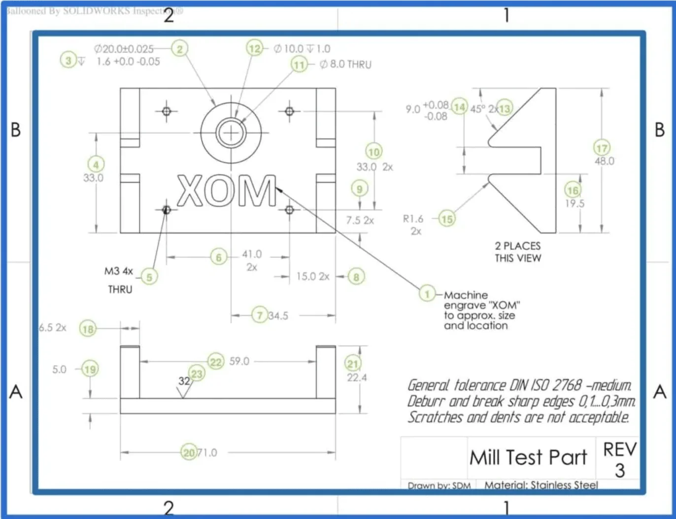
Holes may include counterbores or countersinks. Dimensioning all the aspects of a hole is tedious, and so callouts are used instead. A typical hole callout specifies the hole depth and diameter, the number of identical holes, and the presence of a counterbore or countersinks, along with the depth of these features. Threads should also be of standard thread sizes and need to be specified.
Step 8. Add Tolerances to Critical Features
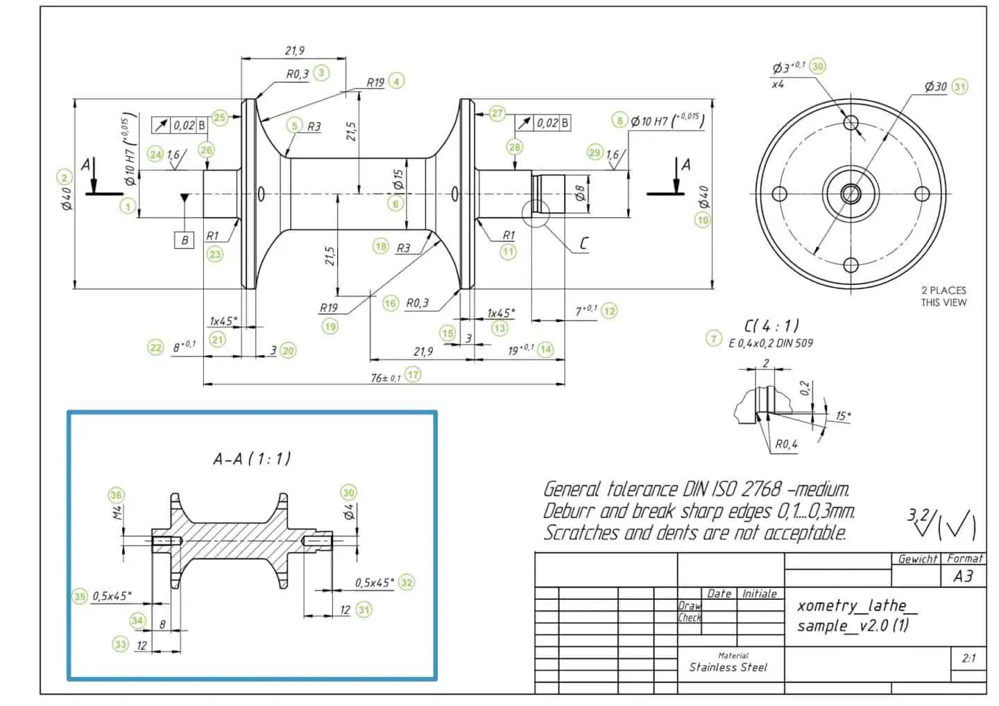
The drawing above indicates a general tolerance of ISO-2768 medium for all dimensions. Tighter tolerances should only be specified where necessary for the part’s intended application.
Tolerances specify a range of acceptable deviations from the values of a dimension. There are various types of tolerances that may be applied to an engineering drawing. These include bilateral tolerances, unilateral tolerances, limits and fits tolerances, and geometric dimensioning and tolerancing (GD&T).
Step 9: Fill the Title Block
Complete all administrative and technical data in the title block, including part name, drawing number, material, scale, and author. An incomplete title block can lead to significant manufacturing errors.
Step 10: Add Notes and Final Review
Use the Notes Block for any remaining instructions, such as “REMOVE ALL BURRS” or specific surface finish requirements.
Final Check: Before submitting, take a break and review the drawing with fresh eyes. Ask yourself: “Could a machinist who has never seen this part before manufacture it correctly using only this drawing?” If the answer is yes, you are ready to manufacture.
Conclusion
A perfect engineering drawing is a clear, unambiguous, and complete instruction manual for manufacturing. By mastering the fundamental components—from line types to tolerances—and following a structured creation process, you can ensure your designs are produced accurately and efficiently every time.
For deeper insights into optimizing your designs for production, explore our comprehensive guides on Geometric Dimensioning and Tolerancing (GD&T) and DfM solutions in the Xometry Pro community.

Comment(0)