

 Europe
 Türkiye
 United Kingdom
 Global


 Login with my Xometry account


As per ASME Y14.5-2018, GD&T consists of 12 geometric tolerances organized into five groups, depending on the aspect of the feature they control: form, orientation, location, profile and runout. The profile group houses two tolerances: profile of a line and profile of a surface.
What Is Profile of a Surface?
Profile of a surface (called surface profile in ISO 1101) controls how much a surface deviates from its ideal shape by creating a tolerance zone around its true profile. The true profile is the theoretically exact shape of the feature, defined with basic coordinate dimensions, basic angular dimensions, basic radii, mathematical data or an appropriate CAD model.
Depending on the datums it references, profile of a surface can control form alone or a combination of size, form, orientation and location relative to the true profile.
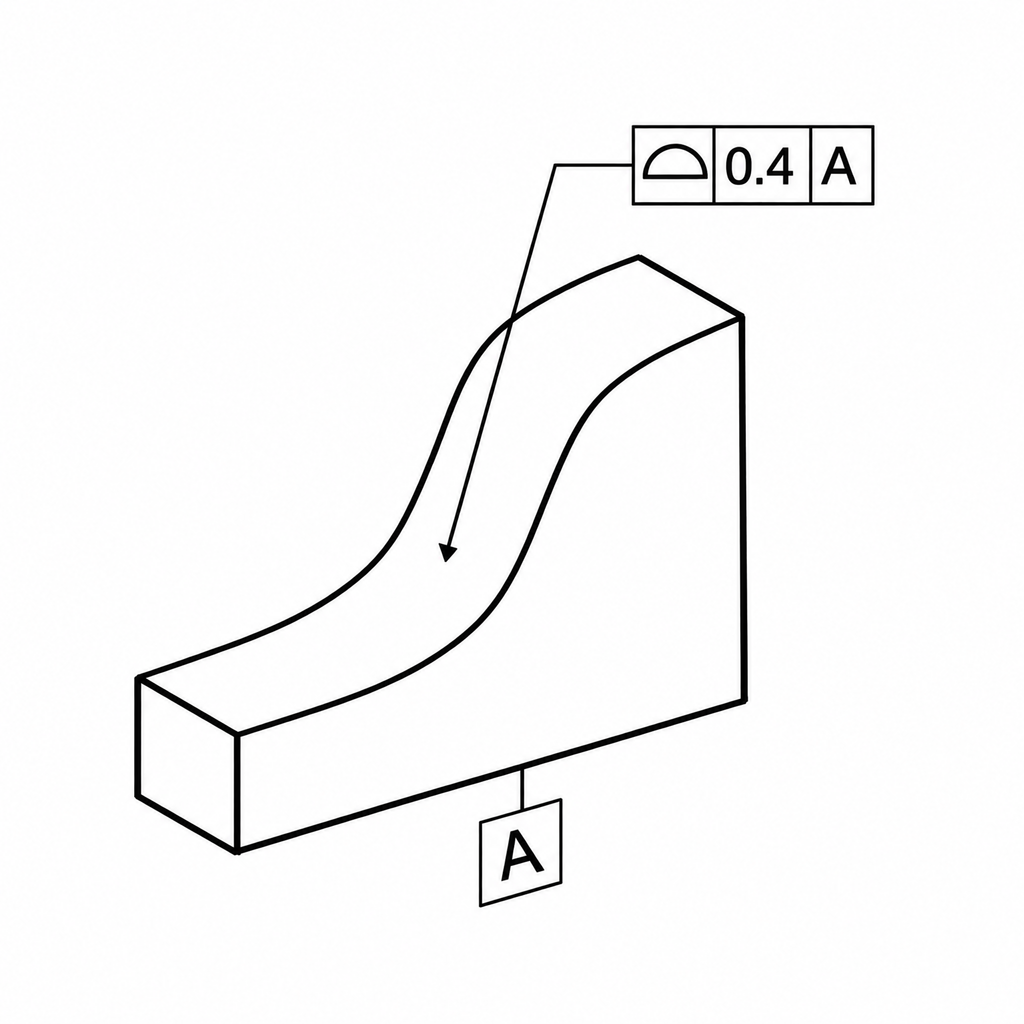
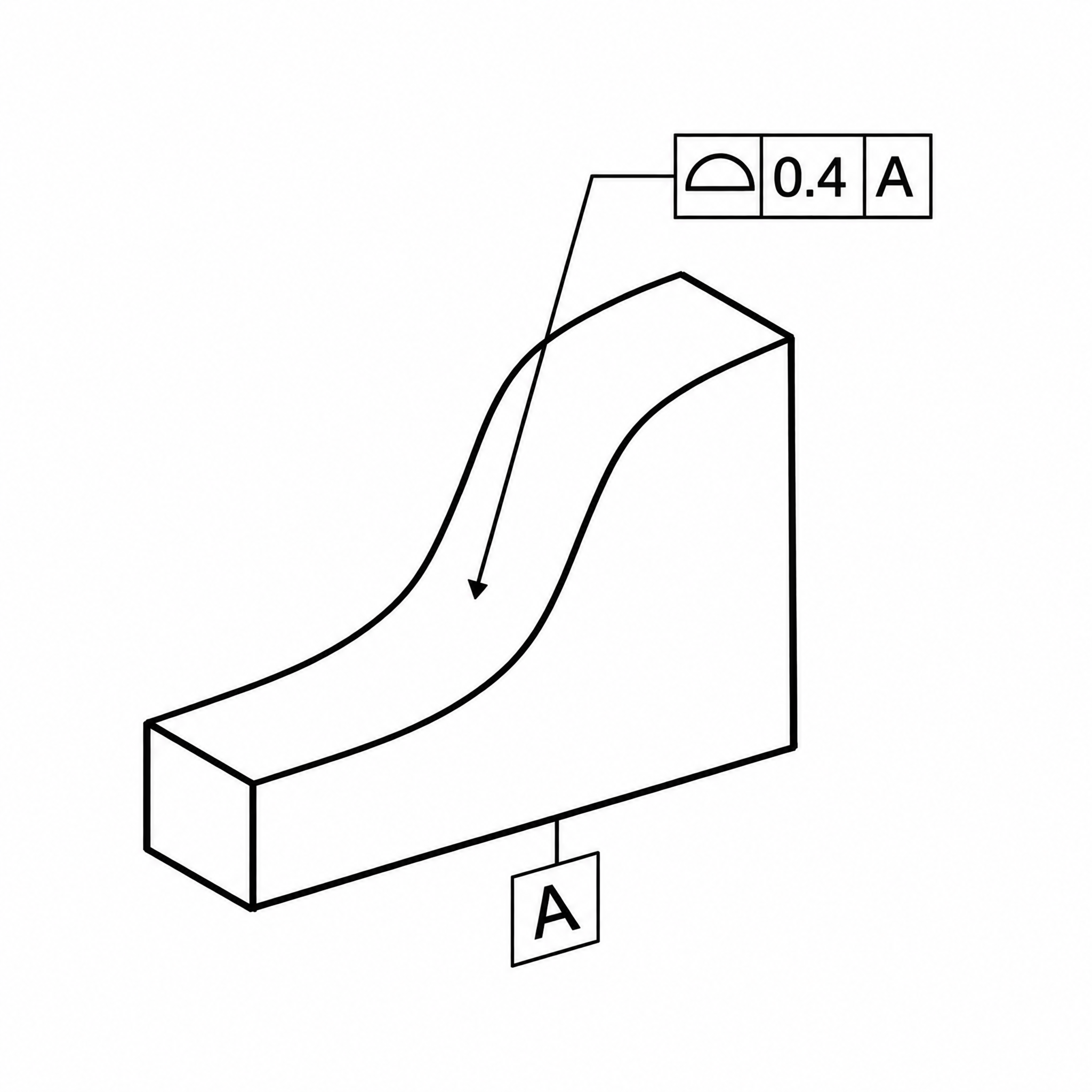
Designers can apply this tolerance to an entire part, multiple features, individual surfaces or even part of a surface. When only a portion of a surface is controlled, the extent of the tolerance must be clearly indicated, such as by identifying the limits of application and using the between symbol (↔).
Parts with highly complex shapes can be controlled effectively using profile of a surface. Where it refines a size tolerance, its tolerance zone must stay within the limits of size, so the profile tolerance value is smaller than the size tolerance.
Real-world example: Airfoil contour
One of the best examples of profile of a surface is an airfoil. The airfoil used in wing, turbine and propeller blades is made up of curved surfaces that generate lift, motion or thrust. The entire shape of the airfoil’s surface is important, and the actual surface must closely conform to the true profile from the CAD model or drawing for it to work satisfactorily.
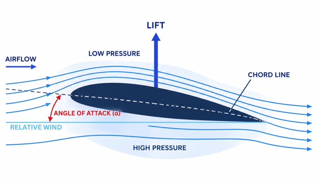
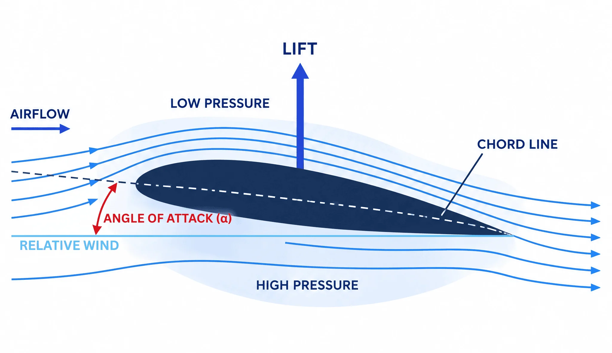
A profile of a surface callout ensures that every point on the controlled surface lies within the specified tolerance zone. When datums are referenced, the callout controls the airfoil surface’s orientation and location as well as its form and size.
Other tolerances cannot do this job. Form tolerances are restricted to basic geometric shapes and cannot mimic a complex aerodynamic contour. Orientation and location tolerances do not define a continuously changing contour, and plus/minus dimensions cannot practically define a freeform contour. Profile of a surface is often the appropriate tolerance for complex curves and freeform surfaces because it controls the entire contour relative to the true profile.
Profile of a Surface Tolerance Zone
In GD&T, a tolerance zone is the region within which the applicable feature or surface must lie. It comes in various shapes.
Profile of a surface uses a three-dimensional tolerance zone established around the true profile. The zone follows the shape of the controlled surface across the entire area it is applied to. It is bounded by two surfaces offset equally on either side of the true profile, measured normal to it, and the distance between them is the total width of the zone. Every point on the toleranced surface must lie within this zone.
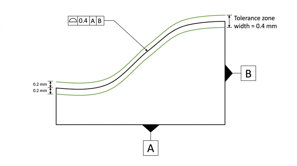
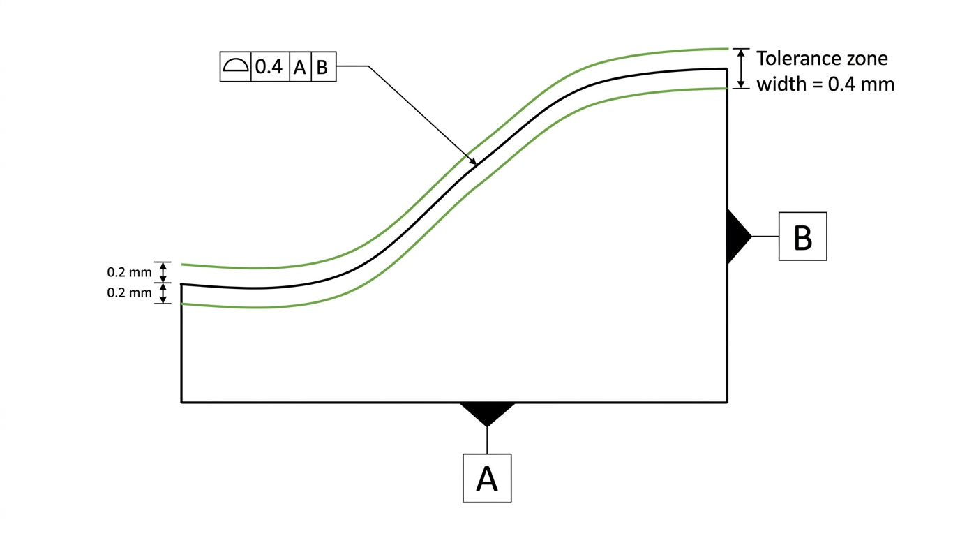
Unequally disposed and unilateral zones
Both profile of a line and profile of a surface can use an unequally disposed zone. It distributes the tolerance asymmetrically when the manufacturing requirements of a surface are not symmetric about the true profile. A circled U symbol (Ⓤ) in the feature control frame marks it.
The value after the symbol is the portion of the total zone that lies on the side that adds material to the feature. On an external surface, that side is outside the part. On an internal feature such as a pocket or bore, adding material moves the surface into the opening. When the value is zero, the zone is unilateral and lies entirely on the material-removing side. When the value equals the total, the zone lies entirely on the material-adding side.
| Callout | Total zone width (mm) | Material-adding side (mm) | Material-removing side (mm) |
| 0.4 | 0.4 | 0.2 | 0.2 |
| 0.4 Ⓤ 0.1 | 0.4 | 0.1 | 0.3 |
| 0.4 Ⓤ 0 | 0.4 | 0 | 0.4 (unilateral) |
| 0.4 Ⓤ 0.4 | 0.4 | 0.4 | 0 (unilateral) |
Values are illustrative.
ASME Y14.5-2009 introduced the Ⓤ symbol as an alternative to phantom lines, and Y14.5-2018 removed the phantom-line practice, so Ⓤ is now the only way to show an unequally disposed zone. ISO 1101 uses the UZ modifier for the same purpose.
Profile of a Surface Feature Control Frame
All GD&T tolerances are expressed on engineering drawings through a feature control frame. The frame is divided into compartments (often called blocks) that state which tolerance applies, its magnitude and the datums it relates to. Read left to right, a profile of a surface frame holds the geometric characteristic symbol, the tolerance, and up to three datum feature references.
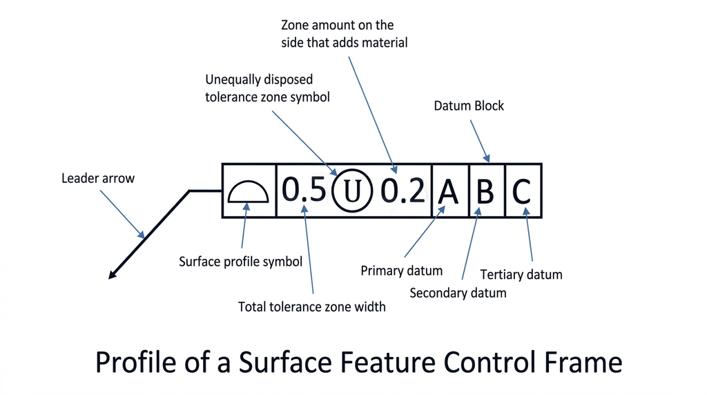
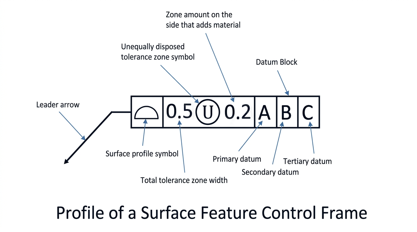
Geometric characteristic symbol
The first compartment houses the symbol for the tolerance being applied. For profile of a surface, the symbol is a half circle closed by a line at its base, with the curved edge facing up.
Tolerance compartment
The second compartment states the tolerance value, which specifies the distance between the two boundary surfaces of the tolerance zone. Unless otherwise specified, the zone is equally disposed on either side of the true profile. When an unequal distribution is needed, the designer adds the Ⓤ symbol after the value, followed by the material-adding portion described above.
Under ASME Y14.5-2018, a profile tolerance applies regardless of feature size (RFS) by default. Maximum material condition (MMC) and least material condition (LMC) modifiers are not applied to the profile tolerance value, so no bonus tolerance is available on a profile callout.
Datum feature references
The remaining compartments hold the datum feature references that establish the datum reference frame. Depending on what is being controlled, profile of a surface may be called out with zero, one, two or three datum references.
| Datum references | What the callout controls |
| None | Form of the surface. Where the surface is curved or closed and its size is defined by basic dimensions, also its size. With no datum reference frame, the zone is free to translate and rotate to fit the part |
| One or more | Orientation and/or location of the profile relative to the datum reference frame, in addition to form and size. The number and order of datums depend on the degrees of freedom to be constrained and the function of the part |
When the callout references a datum feature of size, that reference can carry a maximum material boundary (MMB) or least material boundary (LMB) modifier. The modifier allows the datum feature to shift relative to its true geometric counterpart as it departs from that boundary. This is datum feature shift, not bonus tolerance.
Profile Modifiers and Multi-Segment Callouts
Several symbols change where a profile callout applies or what it controls. Practitioners meet the following most often on ASME Y14.5-2018 drawings.
| Modifier or callout | How it appears | Effect |
| All around | Circle at the bend of the leader line | Applies the tolerance all around the outline of the feature in the view shown |
| All over | Two concentric circles at the bend of the leader line | Applies the tolerance to all surfaces of the part in three dimensions |
| Between | Double-ended arrow (↔) between two lettered limits | Applies the tolerance only between the designated limits |
| Unequally disposed | Ⓤ after the tolerance value | Shifts the zone toward the material-adding or material-removing side |
| Dynamic profile (new in Y14.5-2018) | Small triangle after the tolerance value | Controls form without size: the zone keeps its width but expands or contracts uniformly normal to the true profile. Usually used as a refinement of another profile tolerance |
| Composite profile | One profile symbol spanning two stacked segments | The upper segment locates the surface to the datum reference frame. The lower segment uses a smaller zone that controls form and orientation to the datums, free in location |
On a simple cylinder, a dynamic profile callout with no datums acts much like cylindricity. Its value comes on shapes that no form tolerance can describe. ISO 1101 has a similar idea in its OZ modifier, which offsets the zone by an unspecified amount.
Profile of a Surface vs. Other Callouts
Profile of a surface is a demanding control to master and inspect, so the designer must be certain that a simpler tolerance cannot do the job. Other tolerances can fulfill part of its role, so it helps to know them before deciding. This section compares the two closest alternatives.
Profile of a surface vs. profile of a line
Both profile controls handle complex shapes by enveloping the true profile from the CAD model or drawing. They differ in how much of the part they cover.
| Aspect | Profile of a line | Profile of a surface |
| Tolerance zone | Two-dimensional, applied to a cross section | Three-dimensional, around the whole surface |
| Coverage | Individual cross sections, each evaluated on its own | The entire surface |
| Choose when | Discrete 2D sections are enough and variation in the third dimension is not critical | Continuous control over the whole surface is mandatory |
In simple terms, profile of a surface is the 3D equivalent of profile of a line. Complex parts such as turbine blades and automotive body-in-white (BIW) panels typically call for profile of a surface.
Profile of a surface vs. position
Position and profile can both control location relative to datums, but they apply to different features and establish different tolerance zones.
| Aspect | Position | Profile of a surface |
| Applies to | Features of size such as holes, pins and slots, under ASME Y14.5 | Any surface, including freeform surfaces |
| Zone sits | Around the axis or center plane of the feature at its true position | Along the controlled surface, offset from the true profile |
| Controls | Location, and orientation of the axis or center plane | Form, and with datums also orientation and location, of the surface itself |
| Material condition | MMC or LMC on the tolerance value gives bonus tolerance | Not applied to the value, so no bonus tolerance |
Under ISO 1101, position is not limited to features of size and can also locate surfaces.
How to Measure Profile of a Surface
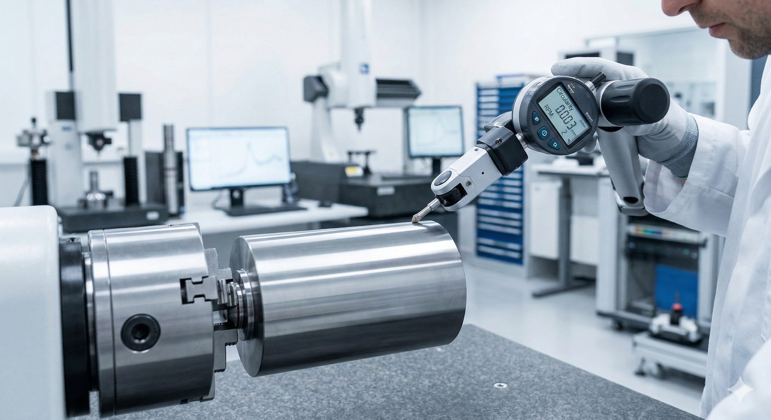
The most common method for inspecting profile of a surface is a coordinate measuring machine (CMM). The CMM probes points on the controlled surface, records their coordinates and compares them with the CAD model or drawing to find the deviation from the nominal surface.
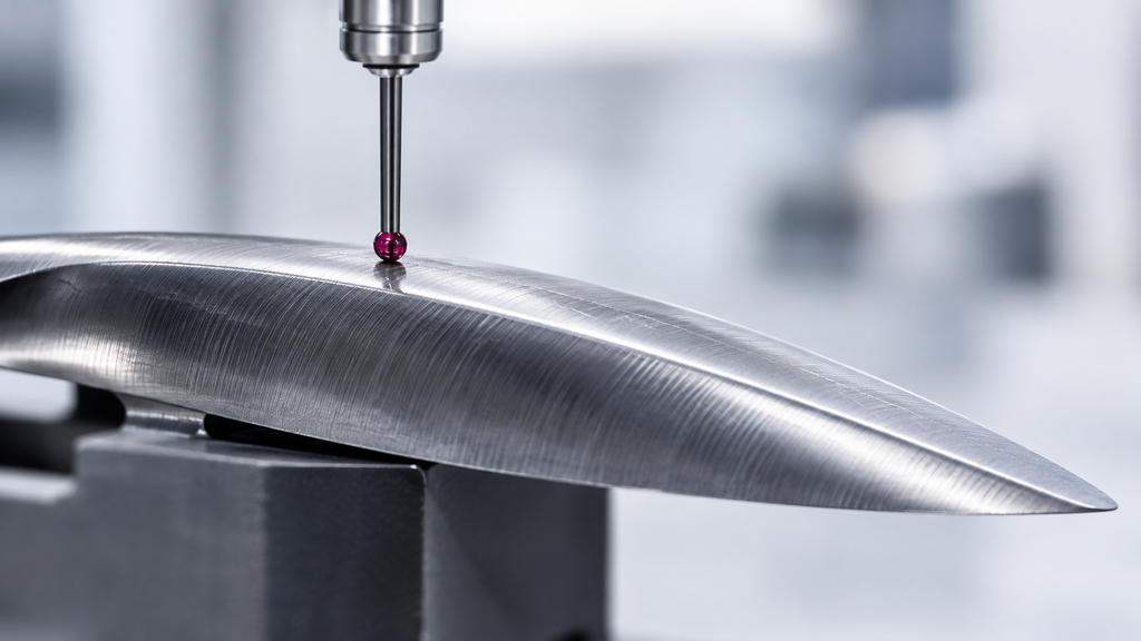
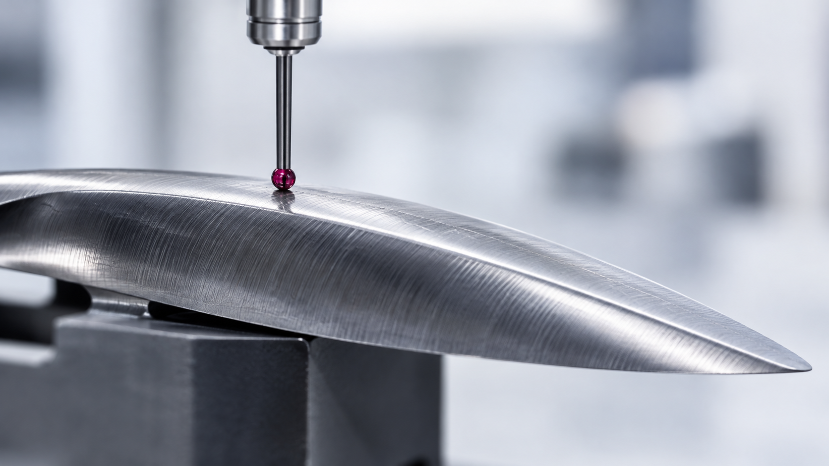
The process involves these stages:
- Establish the datum reference frame. If the callout references datums, the part is aligned to them in the specified order to set the coordinate system for evaluation. If it references none, the software best-fits the measured points to the true profile, because the zone is free to translate and rotate.
- Measure surface points. The CMM measures a strategically selected set of points across the controlled surface. Point density and distribution should suit the geometry, the tolerance and the inspection method.
- Compare the points with nominal data. The inspection software compares the measured points with the true profile. Deviations are generally measured normal to the true profile.
- Evaluate the tolerance zone. The software checks whether every sampled point lies within the tolerance zone.
- Generate the inspection report. The report shows where the measured surface lies inside or outside the zone, often as a color map, deviation plot or tabulated results.
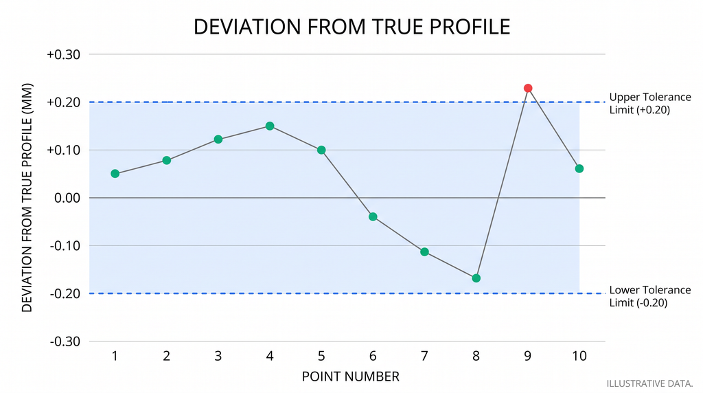
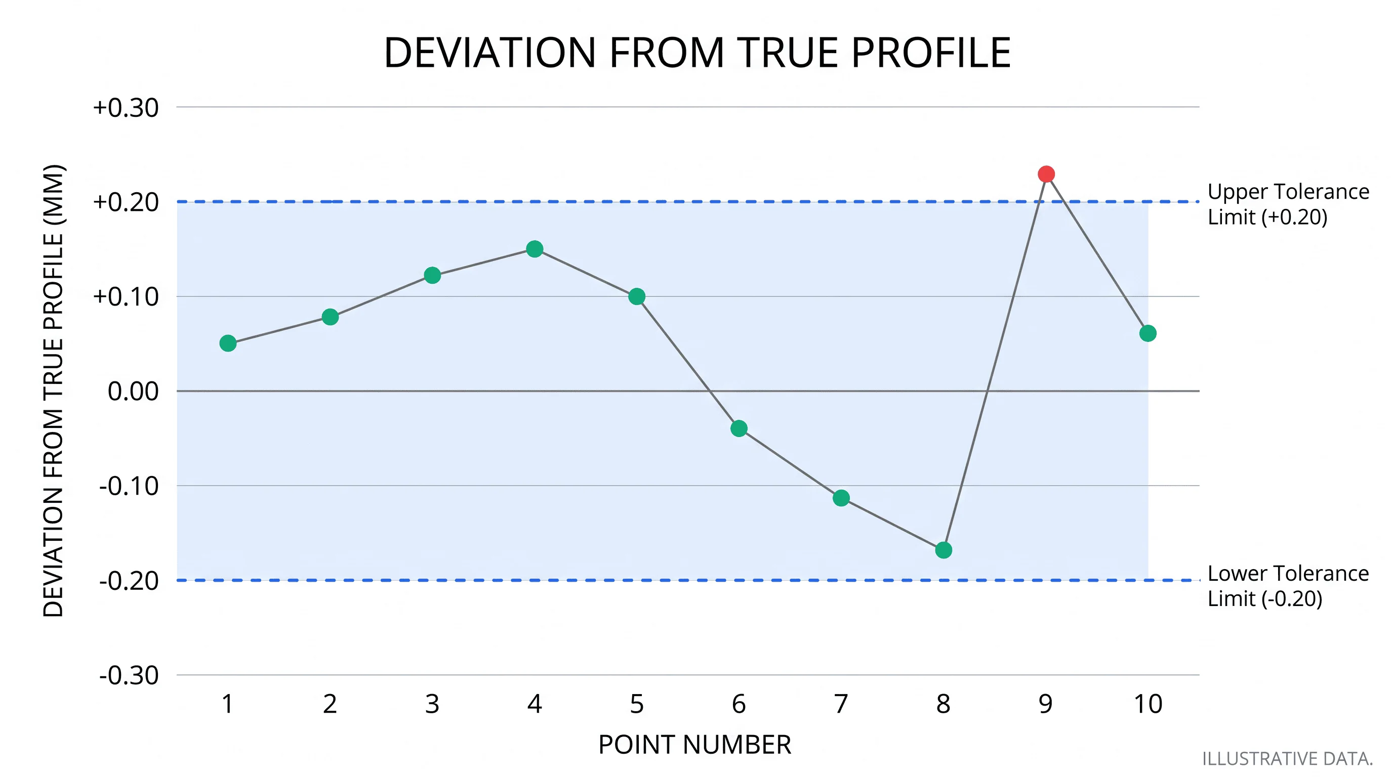
Optical scanners and laser scanners can also measure profile of a surface, which suits freeform parts that need dense point data.
Conclusion
Because profile of a surface is demanding to specify and inspect, ask first whether a simpler control gives the same result. Where it does not, as with turbine blades and automotive body panels, pair the callout with a measurement method suited to the surface. The GD&T library on Xometry Pro also covers perpendicularity and angularity, and the guide to preparing an engineering drawing shows how to present these callouts clearly.
Related Topics
 7
2




Comment(0)