 Europe
  Türkiye
  United Kingdom
  Global


 0
0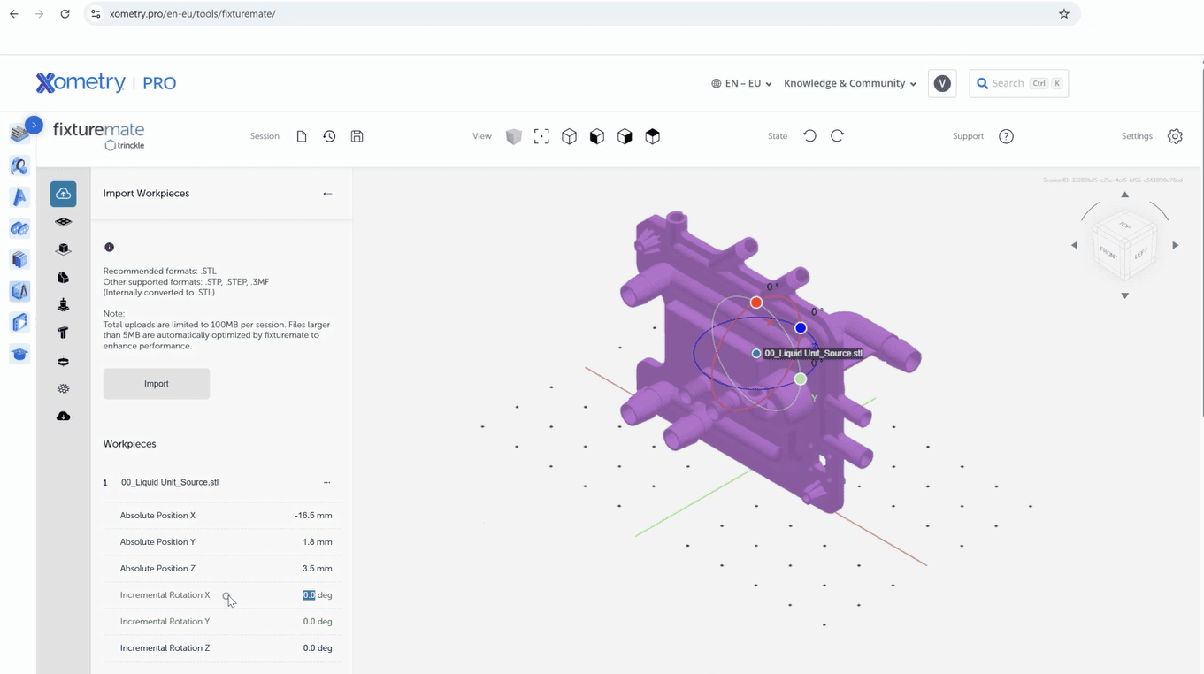
Developed by Trinckle, this tool streamlines the process, letting you create 3D-printable, part-specific fixtures in minutes. Learn how to use this tool step by step, from importing your part and adding supports to fine-tuning details and exporting or ordering the final design.
With this app, you can create fixtures for various applications. For example, these are some of the popular ones:
- Machining fixtures
- Measuring fixtures
- Tool organizers and shadow boards
- Bonding and welding fixtures
- Inspection gauges
- Carrier trays for internal logistics.
Step 1: Import Your Part File
Begin by uploading your 3D model to fixturemate’s browser-based interface. You can find the tool directly on Xometry Pro under Free Tools. Then, follow these steps:
- Go to fixturemate and log in using your Xometry account credentials — the same password you use on get.xometry.eu. If you don’t have an account yet, you’ll need to create one first here.
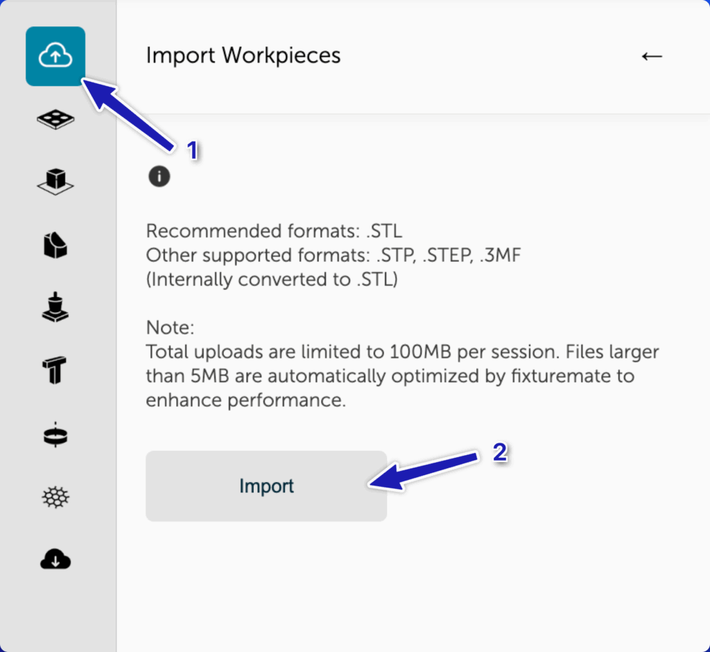
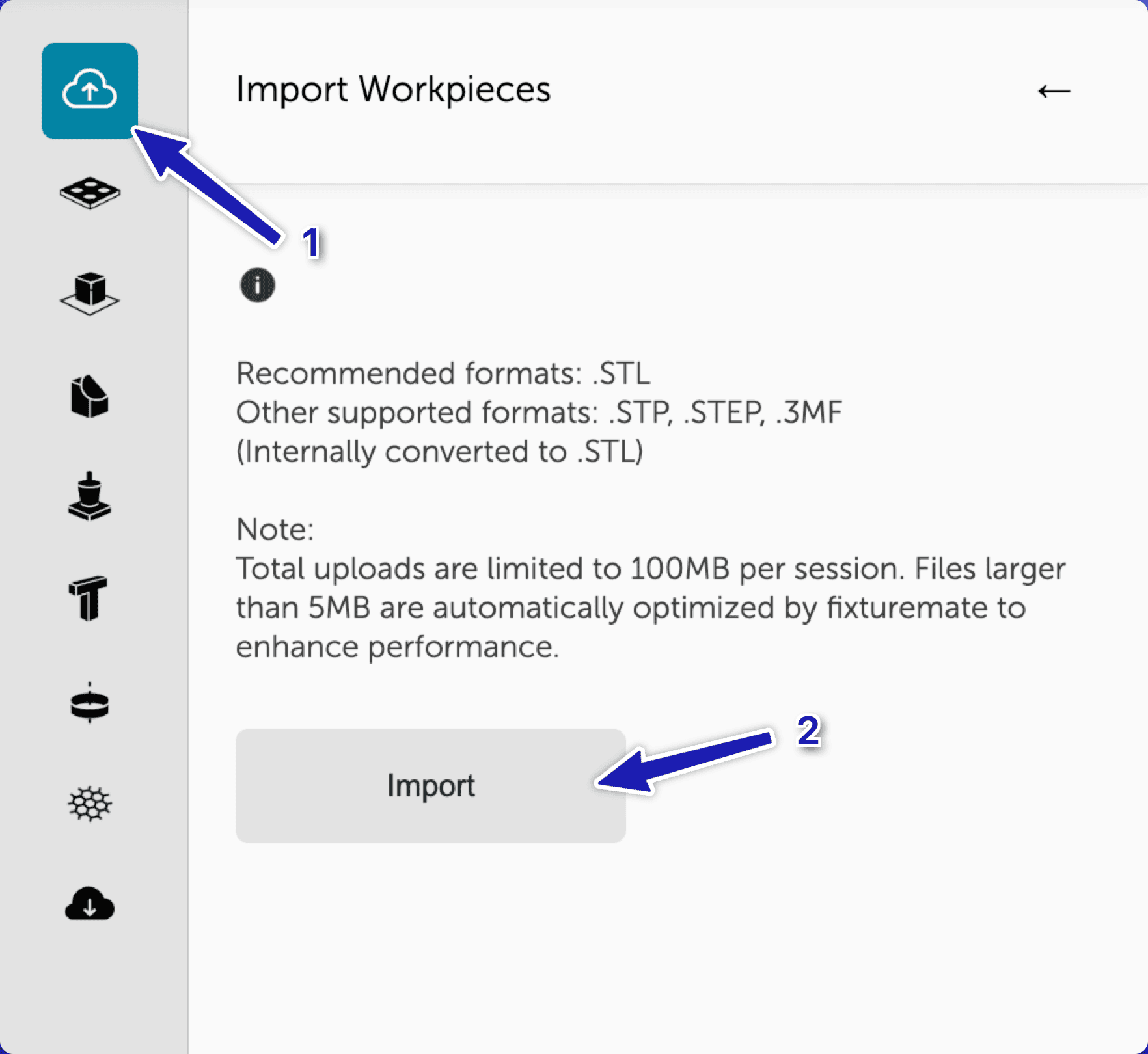
- In the top-left corner, click the cloud icon from the menu and then Import to import a file. Fixturemate supports key file formats, like STL, STEP, and 3MF.
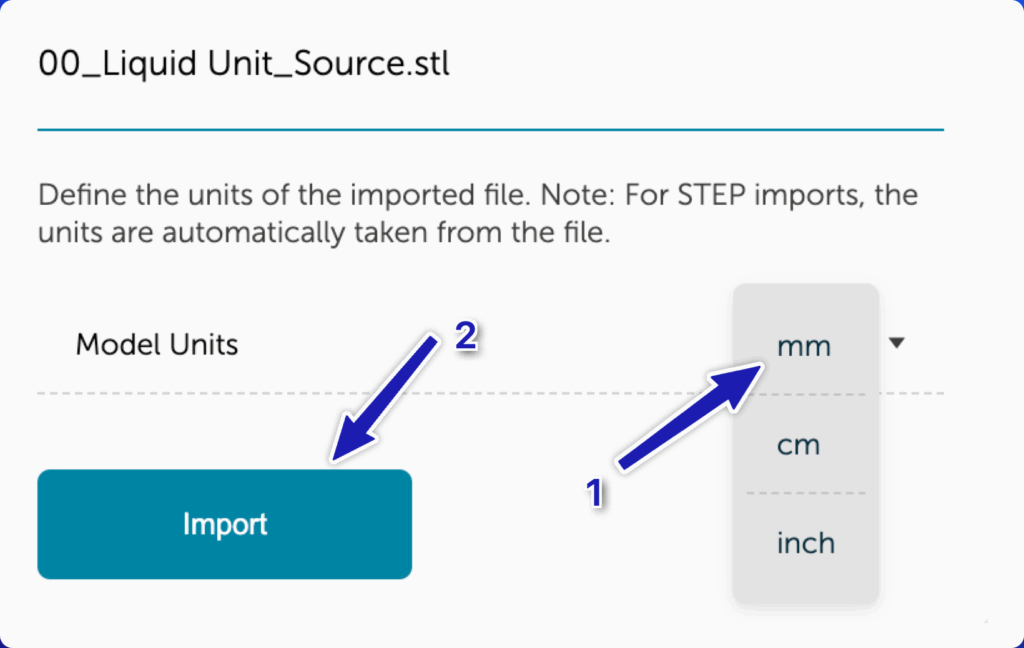
- Navigate to the location of your workpiece on your PC. Choose the workpiece file and then click Open.
- A new dialog box opens, which asks you to choose the model units. Click on the appropriate unit and then complete the Import.

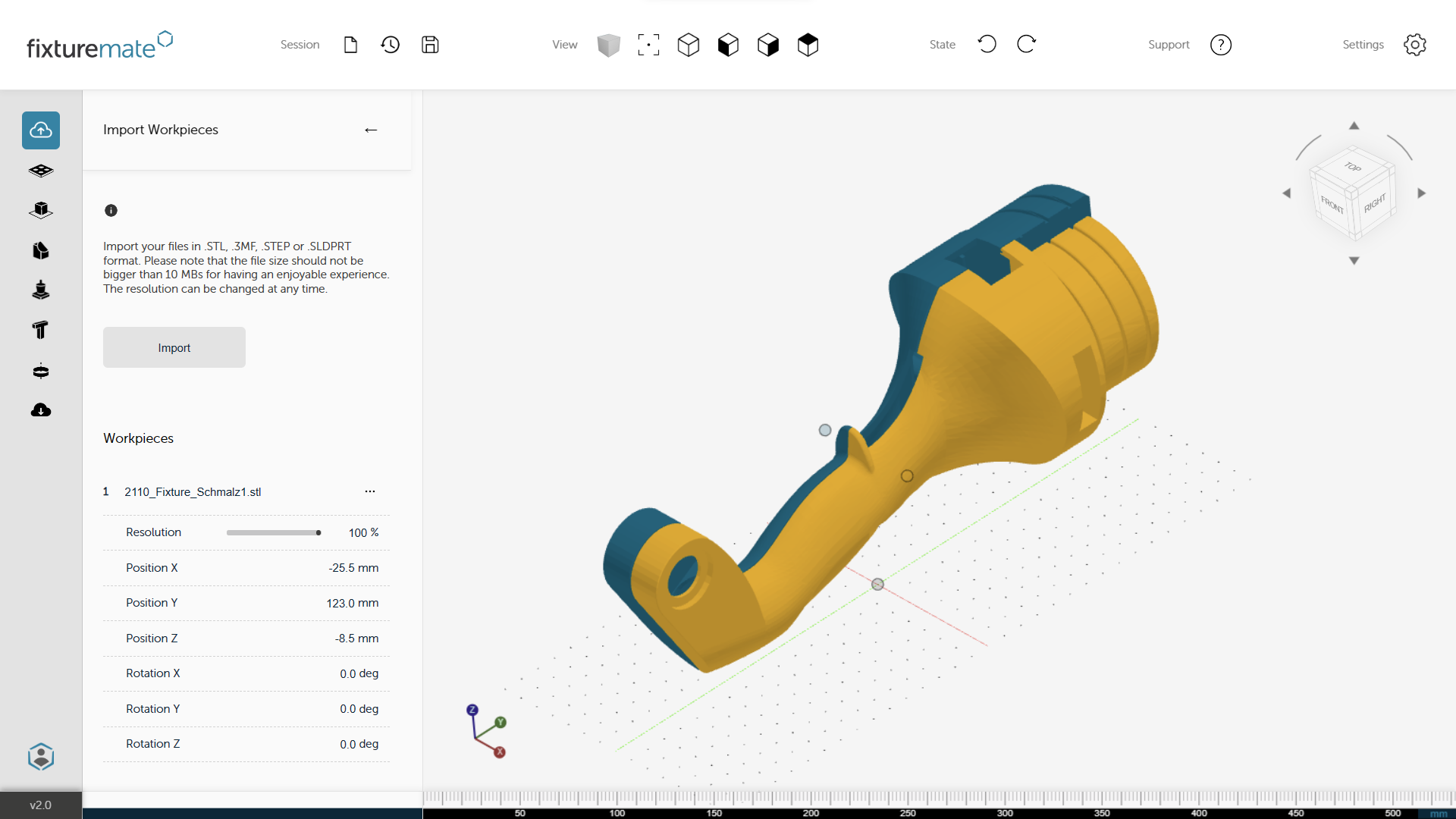
Your workpiece will be uploaded, and you will be ready to start working on it in a few minutes.
Step 2: Define the Contact Surfaces
Mark strong, stable, and non-critical surfaces, and avoid delicate, precise, or functional areas. These are the areas where the fixture will make contact with the part. Let’s explore how to do that in fixturemate.
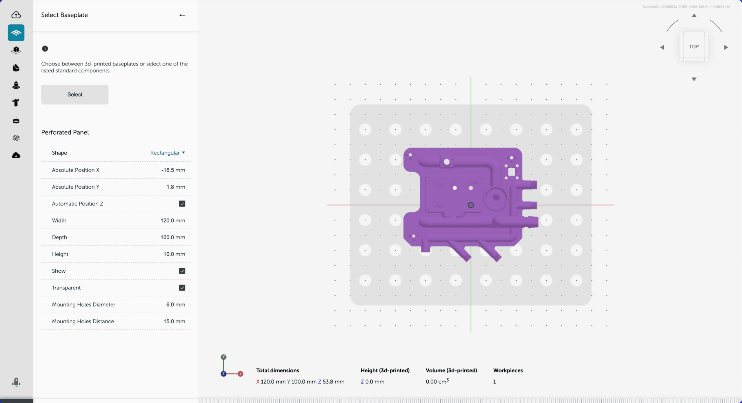
- Add a baseplate to your workpiece:
- Click on the baseplate icon on the menu.
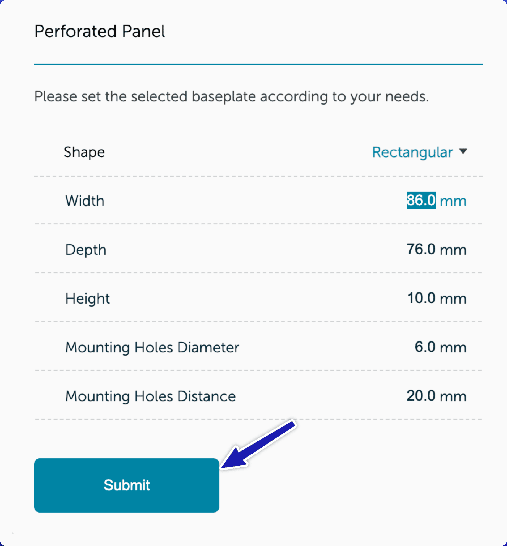
- Choose your preferred baseplate. It can be a rectangular or convex hull. The standard components available in fixturemate are the perforated panel and a metal or wooden plate. Let’s use a perforated baseplate in this guide.
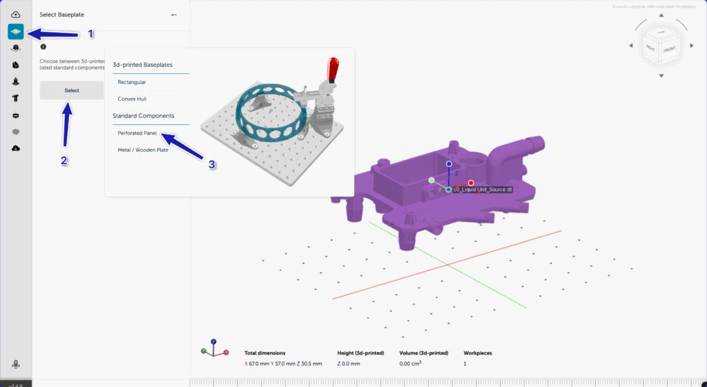
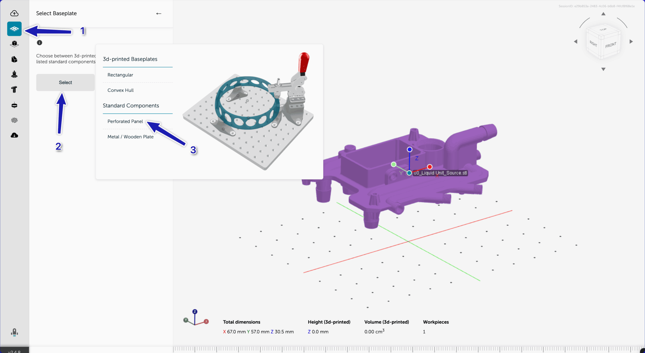
- Specify the shape, width, depth, height, and other parameters. You can use the default parameters. These parameters can be changed later on as needed. Once completed, click Submit.
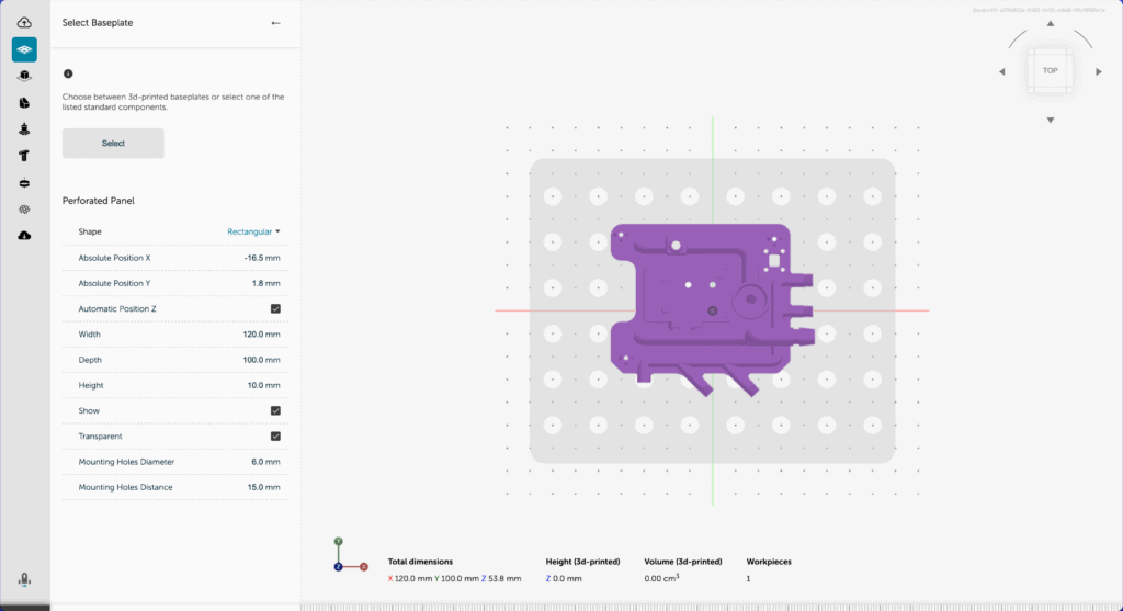
For our example, you don’t need to make any size or orientation adjustments since the part fits on the baseplate (see the top view below).
Step 3: Add Supports
Fixturemate allows you to create support pillars in various shapes, including rectangular, cylindrical, conical, and custom-shaped or polygonal. Each shape is best suited for a specific use. For example:
- Use rectangular supports for broad, flat contact areas.
- Use cylindrical supports for round or localized support zones.
- Use custom shapes when the support area is irregular or complex.
Let’s keep things simple by using only rectangular support structures in this guide. This procedure remains the same for other shapes. Proceed as follows:
- Select the support icon from the menu.
- Click Select and then choose Rectangular.
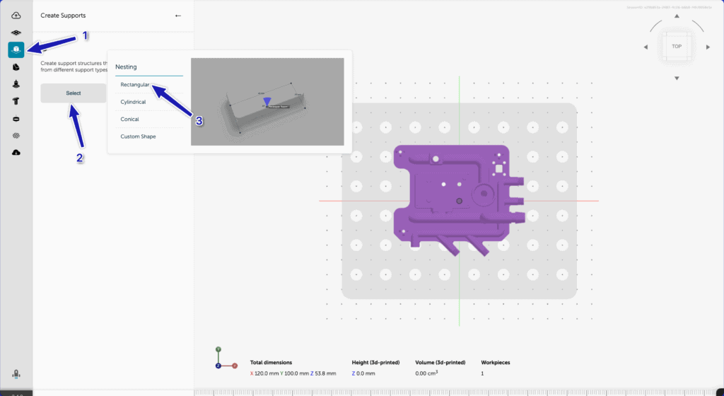
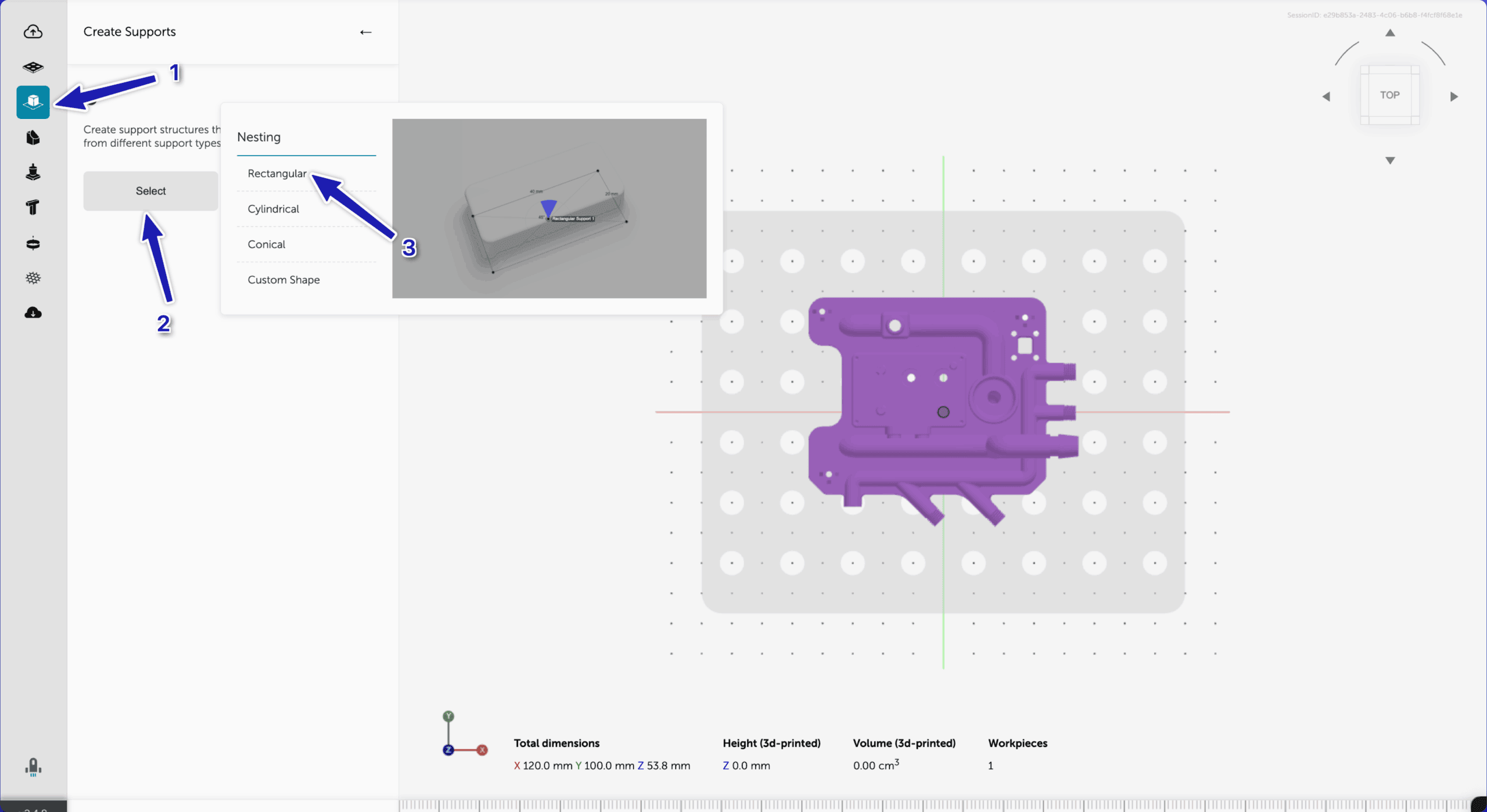
- Use the crosshair tool to click on the baseplate to define the support’s center. Click once to set the center point, and then move your mouse and click again to add the size and orientation. Fixturemate will automatically extrude the pillar to touch the bottom of the workpiece.
- Follow the above procedure to place all the remaining support structures. The size can be adjusted from the support menu on the left.
Step 4: Adjust Fixture Parameters
The next step is adjusting the fixture settings to match your specific application. Adjustable parameters in fixturemate include the following:
- Fixture height: Determines the elevation of the part from the base.
- Wall and base thickness: Controls structural strength and print time.
- Support structure type: Choose from options such as posts, ribs, or frames for different levels of rigidity and material savings.
Proceed as follows to adjust the height and width of any support structure of your choice:
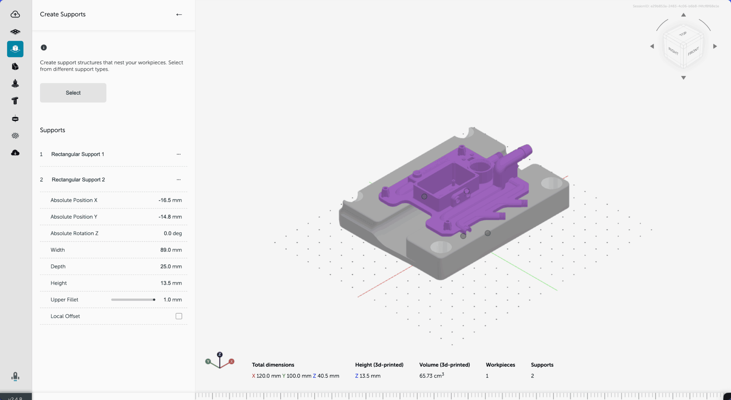
- Identify the center point of the support structure and click on it. This will activate the menu items on the left, where you can manually type the desired height and width. Repeat the process for all the support structures on your workpiece.
- You may find that the workpiece interferes with the support structures. Let’s deal with that from the fourth item in the left-hand menu. This allows us to subtract workpieces.
- The first thing you want to do is to raise the workpiece a few millimeters above the baseplate for a clearer view. Click on the center point of the workpiece and adjust the absolute position z accordingly.
- To remove the interference, click the fourth icon on the menu and then the checkbox. A prompt window will appear, allowing you to set the global offset and preview resolution according to your requirements.

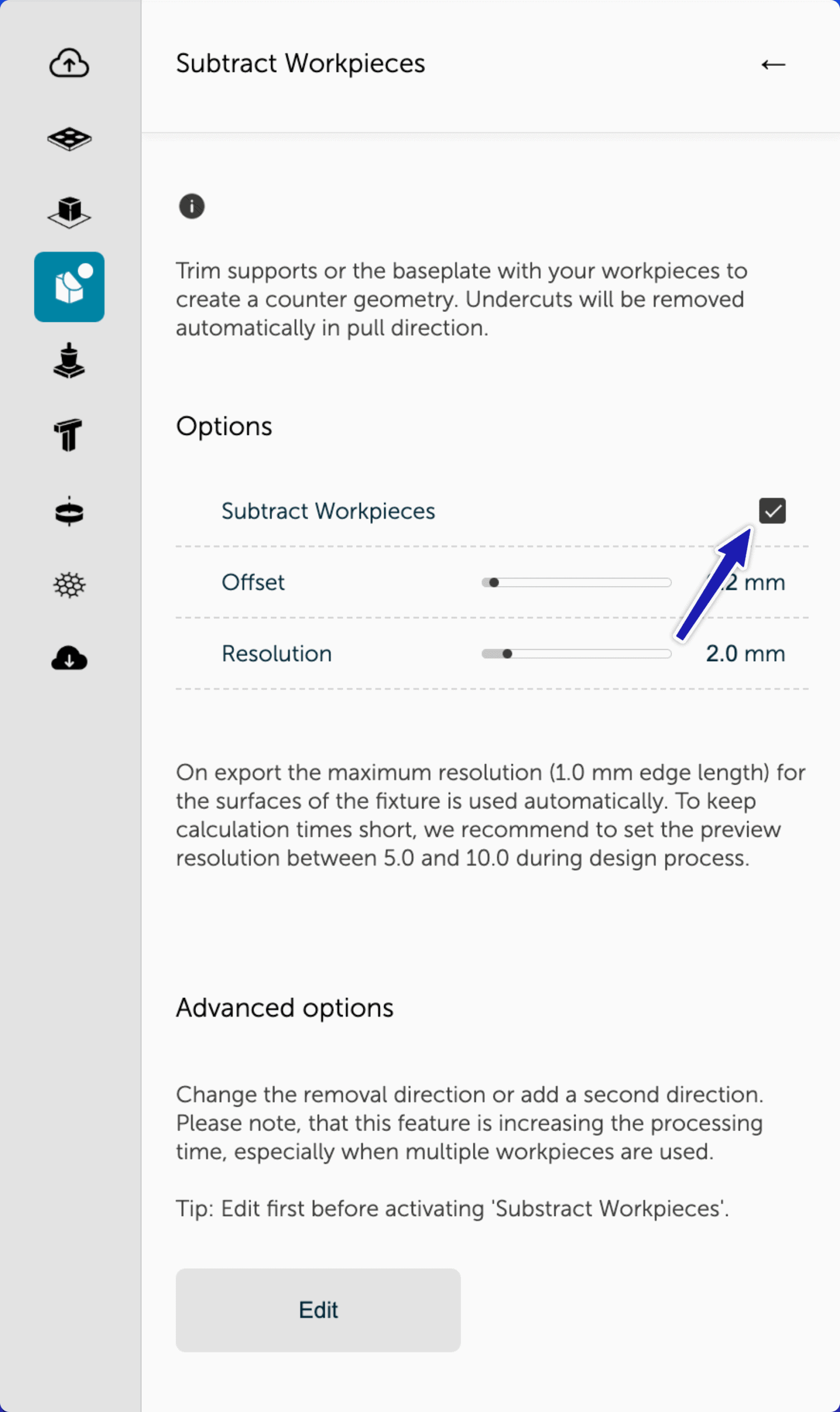
- This will subtract the geometry of the workpieces from the interfering support structures. Here you have the option to define the global offset, which will apply to all support elements. This value can be fine-tuned to enable a snug fit when the workpiece is fitted into the fixture.
Bonus Step
If the design doesn’t include a 3D-printed baseplate, attach the support elements to the baseplate manually. To do that, right-click the center dot of the support element and select mounting from the context menu.

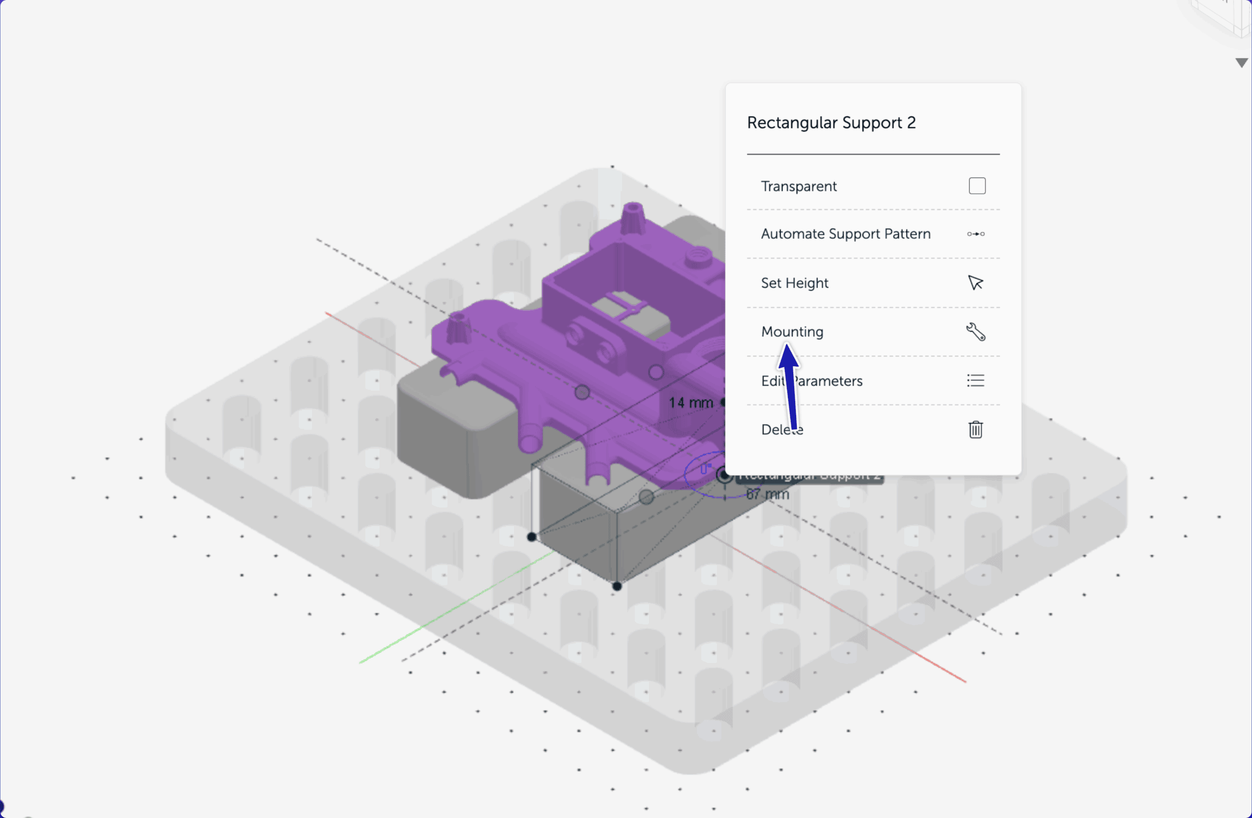
You can then click to activate the surrounding red dots of the support element where you want it to be mounted. If you make a mistake, you can right-click and select delete to erase the red dot, or left-click and drag to move it to a different hole.
Adjust the mounting base thickness, counterbore diameter, and center bore depth accordingly. Click Finish to complete the mounting creation. Repeat this procedure to create mountings for all support structures in your design.
The completed workpiece, with all support structures and mounting holes, is shown below.

Step 5: Preview and Validate the Design
Fixturemate provides real-time 3D visualization of the fixture and your part together. This step is critical for checking and confirming the following:
- Orientation and part positioning
- Adequate support without interference
- Smooth probe clearance if the fixture is intended for CMM inspection
Make all necessary changes and correct all spotted mistakes at this step to ensure the exported file is error-free and ready for 3D printing.
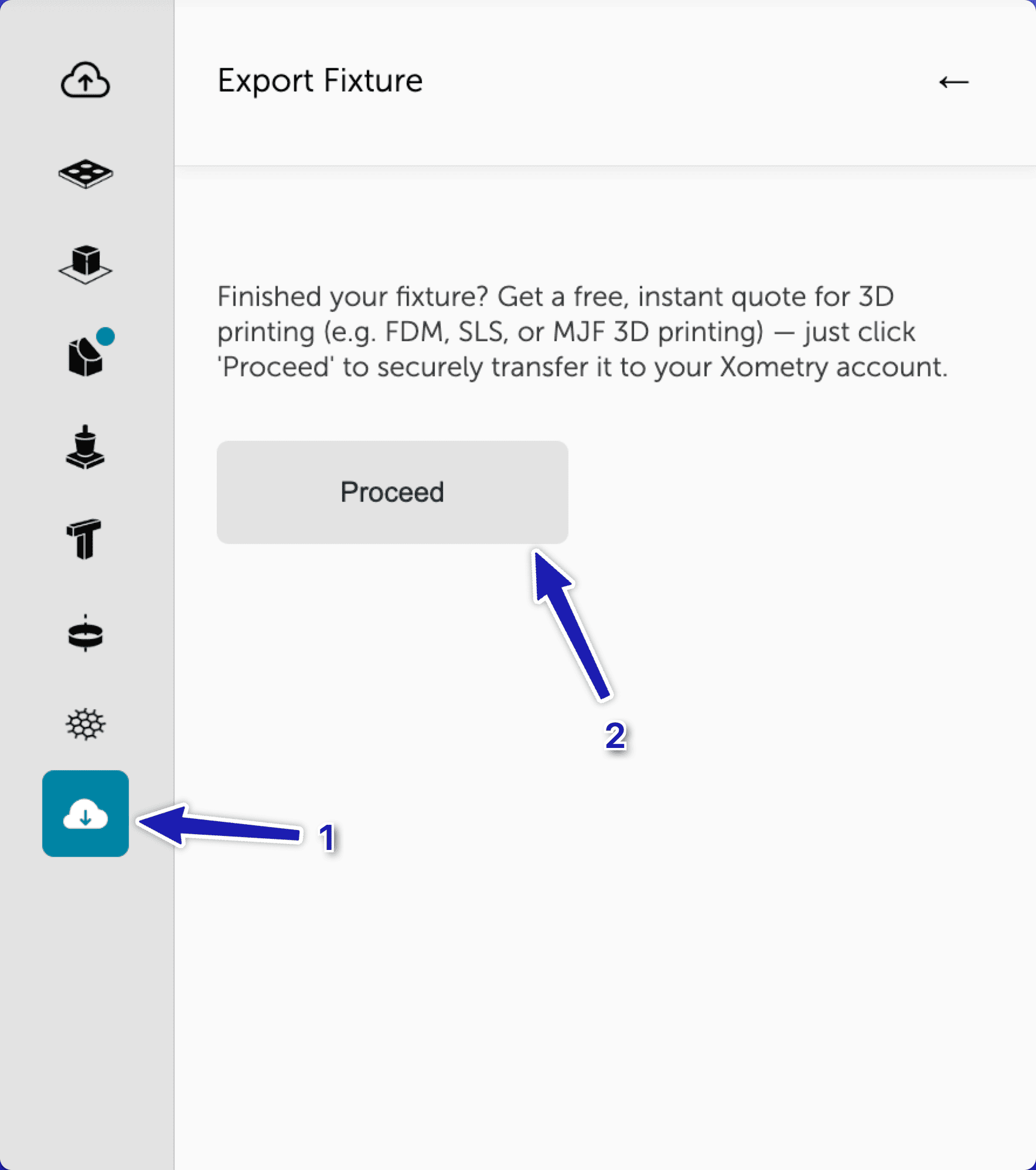
Step 6: Order the Fixture
After validation:
- Order the fixture directly through Xometry’s manufacturing network, with instant quoting and material selection.
This option allows teams to leverage Xometry’s production capacity for professional results.
Click on the last icon from the menu on the left side and then click the proceed button. Your design will be automatically pushed to Xometry.

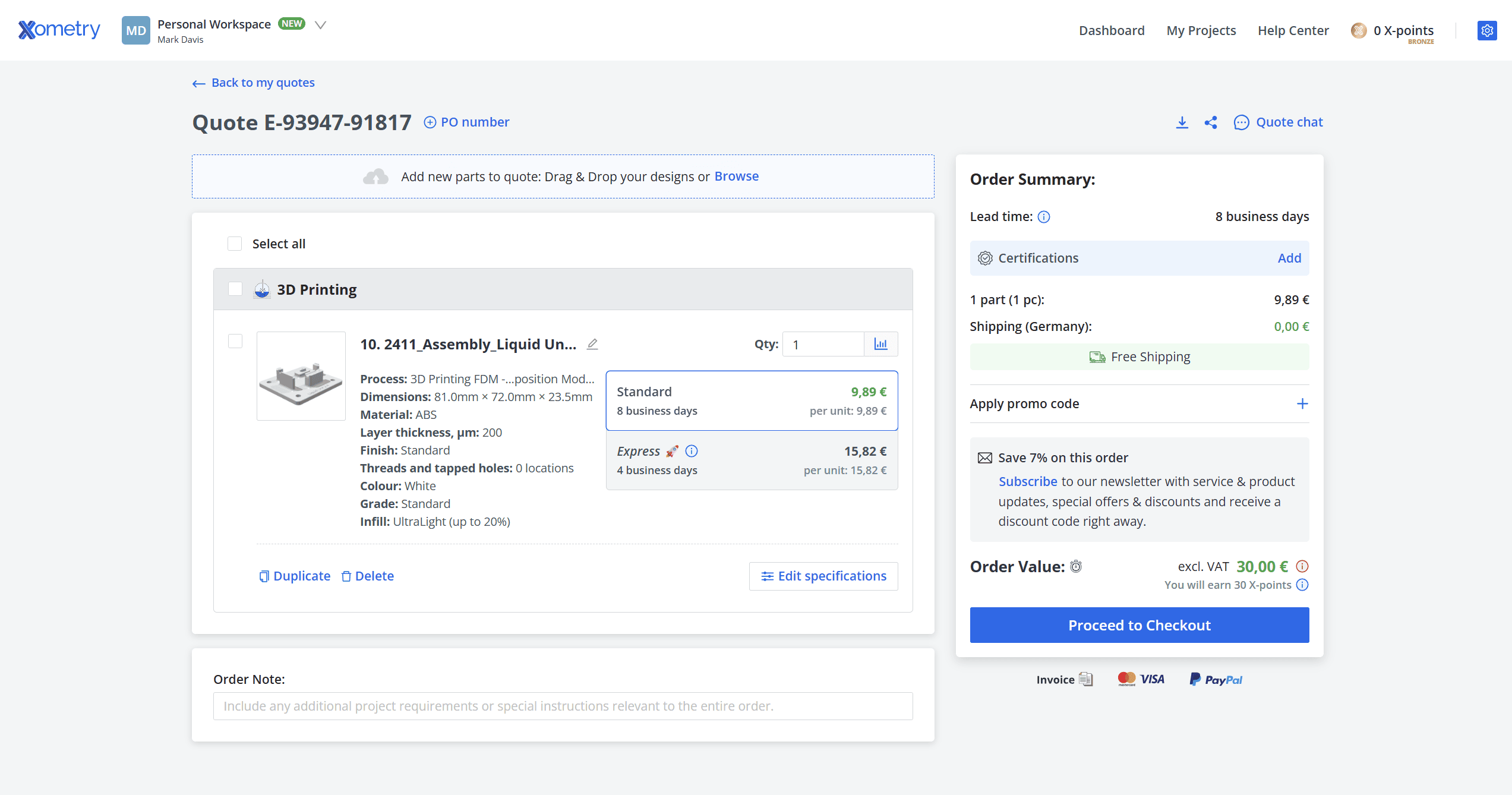
How to Order Fixtures Using Xometry’s Manufacturing Network
As soon as your fixture is complete and you are redirected to your customer account on Xometry, you can select the 3D printing technology, material, and surface finish option that best suits your application. After making your selections, the system will automatically generate an instant quote — no need for additional CAD work or manual adjustments.

Your Next Step in Smarter Fixturing
Whether you’re preparing for CMM inspection, assembly, or work holding, fixturemate enables you to go from part file to ready-to-print fixture in minutes. Try fixturemate and experience a faster way to create custom 3D-printed fixtures.
fixturemate: Custom 3D-Printed Fixtures in Clicks
Easily design custom fixtures with a free, intuitive tool. Export 3D files optimised for 3D printing in just 20 minutes to your Xometry account.

Test it out and let us know your thoughts or share your feedback in the comments below.


Comment(0)