 Europe
  Türkiye
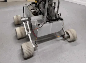
One of the major hurdles in our project was mobility: how to build a reliable, puncture-proof wheel that could handle rocks, slopes, and sand while staying within strict constraints on weight and size.
Instead of relying on pneumatic tyres, which are prone to failure in rugged environments, we set out to develop a fully airless, flexible wheel—capable of passive damping, lightweight, and manufacturable via additive techniques. The project turned out to be far more than just a component design: it became a case study in engineering decision-making, design iteration, and real-world manufacturing collaboration.

Three Concepts, Three Philosophies
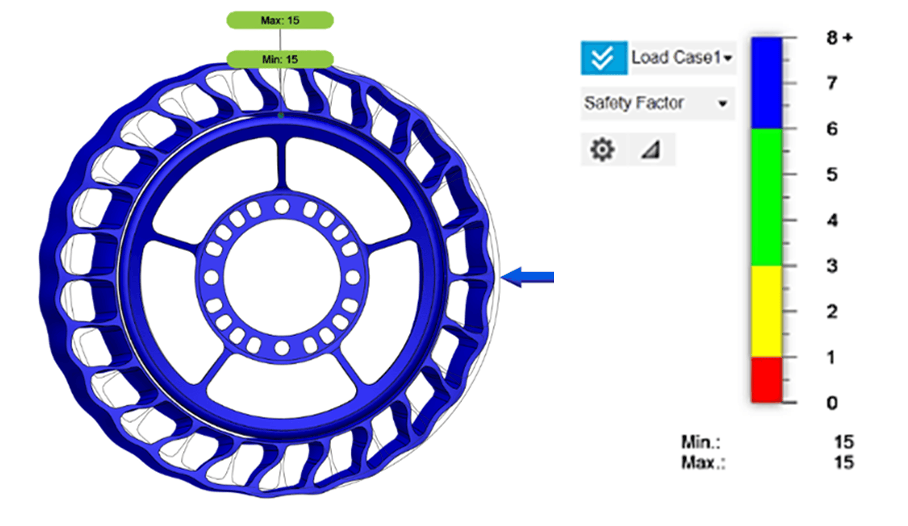
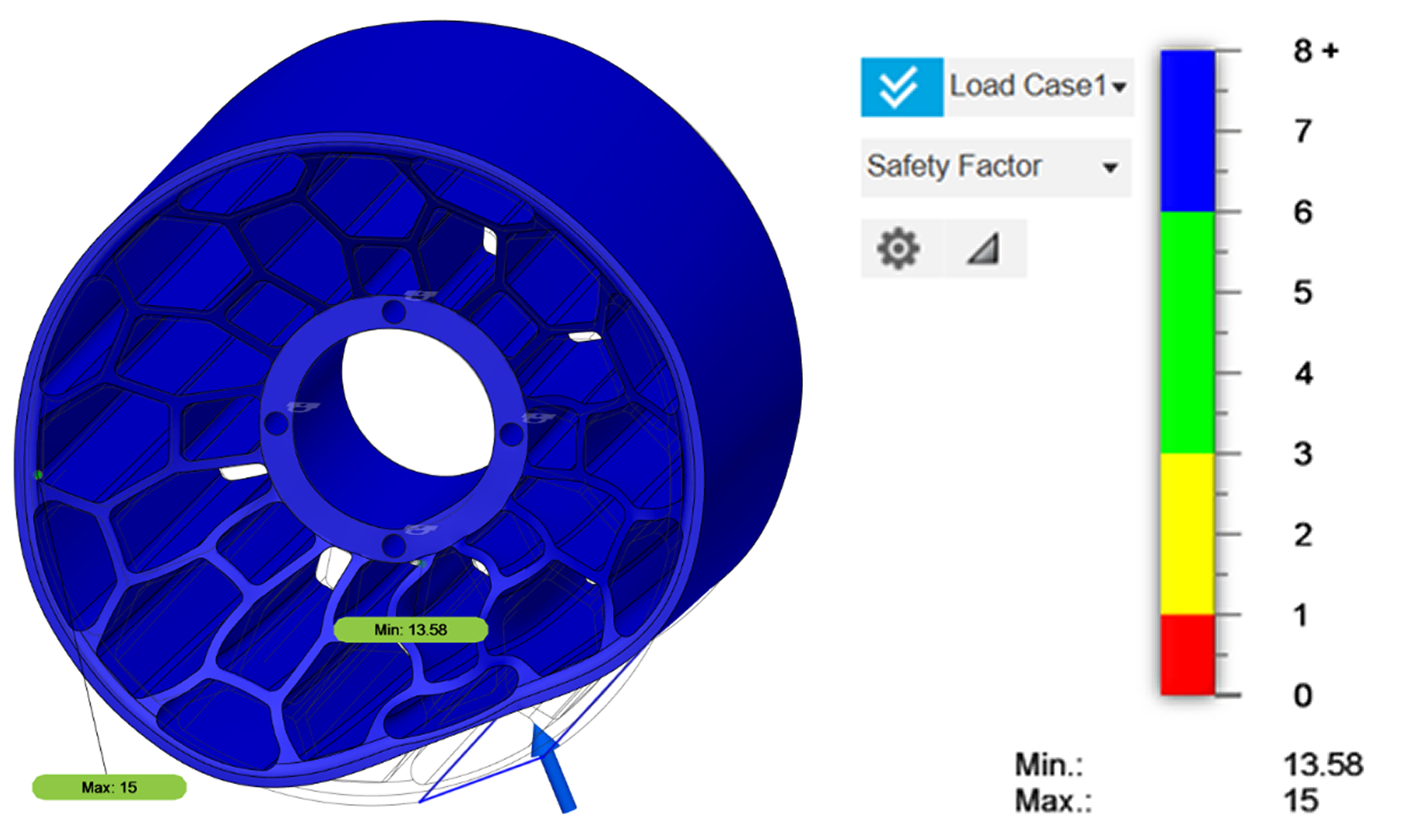
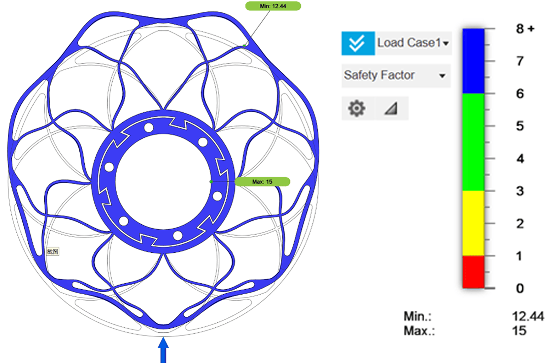
We began by developing three distinct design concepts, each exploring different structural strategies and material combinations. To meet competition constraints—a maximum wheel diameter of 220 mm and the ability to withstand a vertical load of 120 N—we evaluated each concept through detailed CAD modeling and finite element analysis (FEA). Performance was assessed based on safety factor, weight, manufacturability, and how the structure deformed under load.
| Concept | 1. Rigid core + flexible outer layer | 2. Single-piece honeycomb | 3. Modular assembly with locking teeth |
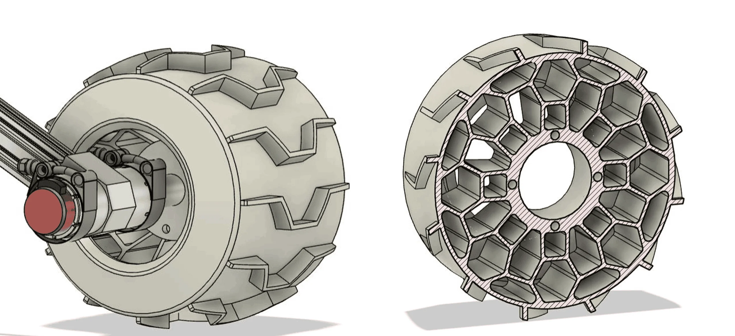
| Description | This design combined an ABS core with a TPU outer layer, connected via an interference fit—like a conventional tyre on a rim. | A one-material, one-piece TPU design using a hexagonal honeycomb structure for uniform strength and reduced mass. | Also dual-material (TPU + ABS), but with the outer layer attached to the core via interlocking teeth—allowing easier servicing. |
| Mass | 1.290 kg | 1.095 kg | 1.043 kg |
| Effective safety factor | 7.5 (with a conservative assumption of 0.5x applied to printed parts) | 6.79 | 6.22 |
| Advantage/drawback | Localized stress and potential tearing at the press-fit interface. | Simplified manufacturing, robust load distribution, better deformation control. | Uneven deformation patterns and stress concentration risks from sharp edges. |
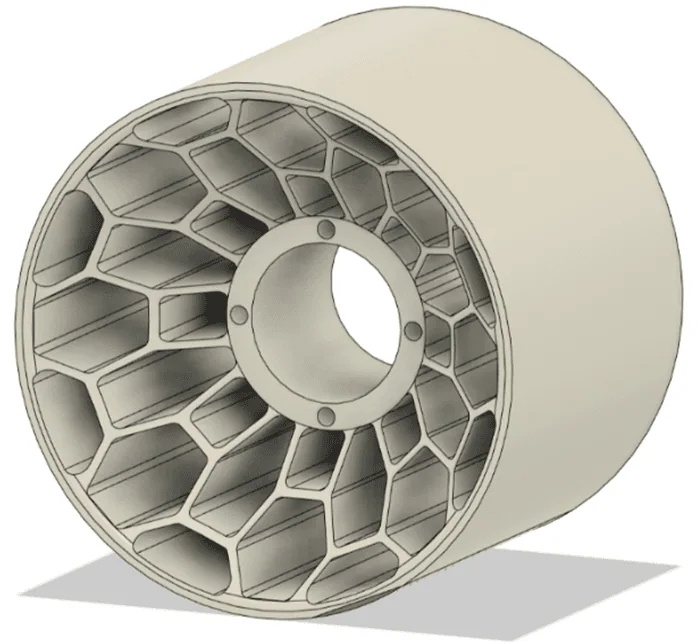
After benchmarking the options through a weighted decision matrix, we selected Concept 2 for further development. Its superior manufacturability and consistent structural response made it the best candidate. The clean, single-material design also aligned well with additive manufacturing methods, and we validated its feasibility early on using Xometry’s Instant Quoting Engine.
From Preliminary Specs to Final CAD
With Concept 2 selected, we refined the design to meet a series of strict functional requirements:
- Max wheel diameter: 220 mm
- Load capacity: 120 N
- Motor interface: recessed cavity to minimize moment arm
- Texture: tread for traction
- Coverage: partial dust covers to block debris
- Flexibility: elastic deformation for damping
- Single-piece manufacturing to minimize failure points.
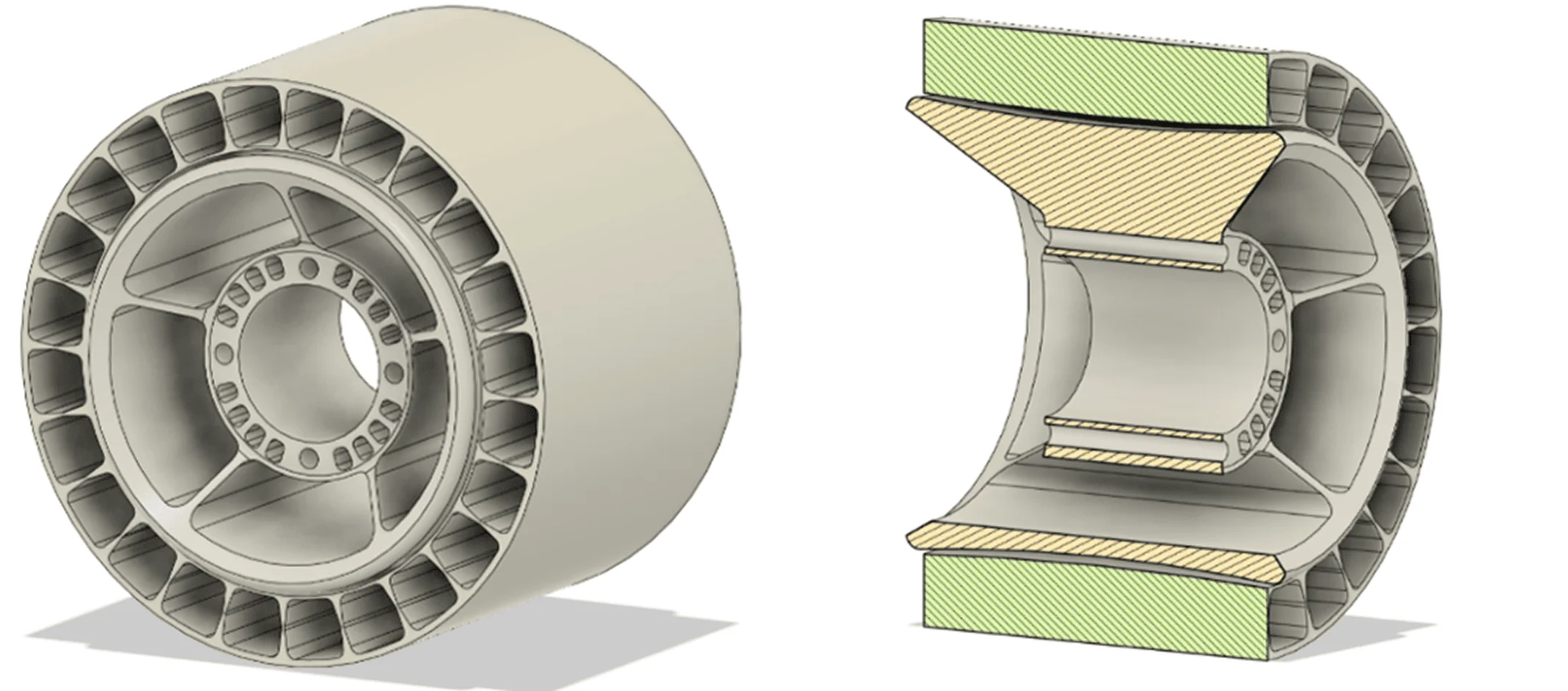
The resulting CAD integrated a full enclosure for the motor shaft, preserving the honeycomb core for strength and incorporating a textured tread for grip on both flat and inclined surfaces.

To validate our approach and select final manufacturing parameters, we reached out to Xometry engineers for a professional design review. Their feedback pushed the project to the next level:
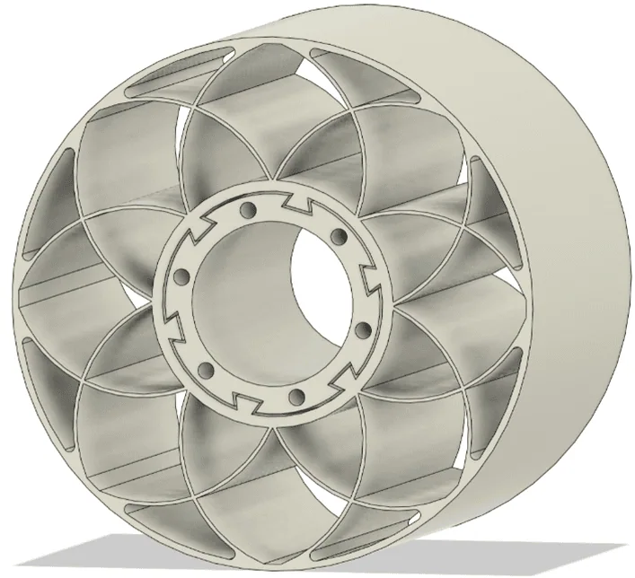
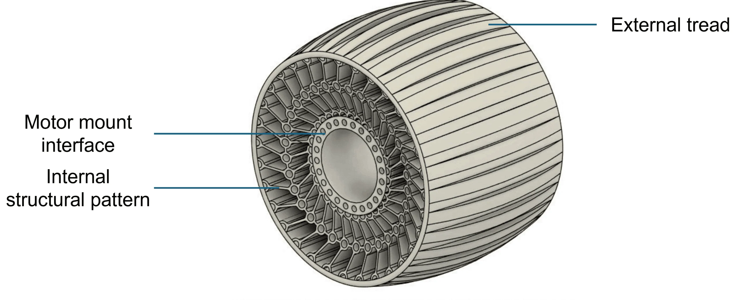
- Revised lattice: Our initial design showed uneven deformation around the circumference. Engineers recommended a more symmetric, radial internal strut layout, inspired by Michelin’s Uptis prototype.
- Dust cover removal: Partial covers risked trapping fine dust and gravel. A fully open design would eliminate that and improve aesthetics.
- Tread optimization: We lowered tread height and switched to a symmetric pattern to support bi-directional driving and reduce wear.
- Material hardness tuning: Shore A >70 was advised to balance softness and structural support. EOS TPU 1301 (Shore 86A) was the final pick—ideal for impact damping, UV-resistant, and compatible with Selective Laser Sintering (SLS).
All this feedback was incorporated into our final CAD, which featured a uniform internal lattice, motor mount integration, and a symmetric tread pattern. The partial dust cover was dropped altogether.
Manufacturing, Delivery, and Integration
With the final design ready, we uploaded it to Xometry’s platform for a second quote. TPU 1301 wasn’t listed in the dropdown at the time, so we selected “TPU” and specified the exact material in the order comments. Thanks to Xometry’s 80% sponsorship, we were able to manufacture all six wheels within our student budget.
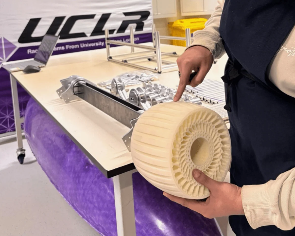
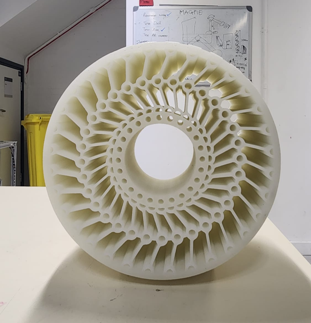
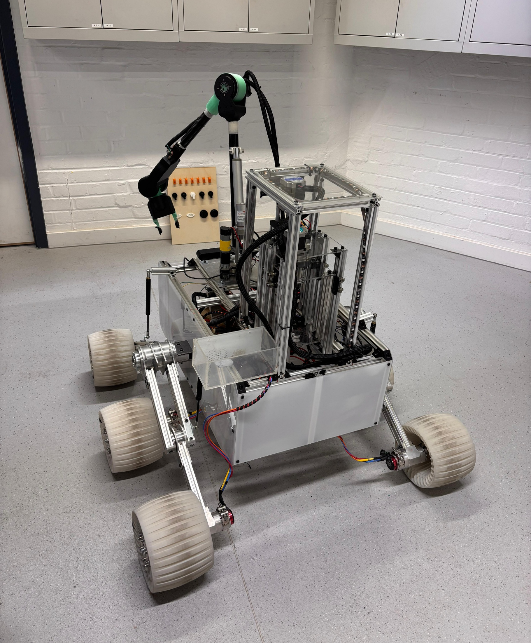
When the printed wheels arrived in February, the quality was exceptional. The SLS process delivered the dimensional accuracy we needed, and the parts exhibited excellent flexibility without visible defects. After successful flexure testing, we mounted the wheels on the rover chassis. The integration was seamless—the offset cavity locked into the motor shaft perfectly, and the honeycomb structure provided the shock absorption we had modeled from the start.
Engineering Lessons Beyond the Classroom
This project was more than a design exercise—it was a crash course in real-world engineering. Key takeaways:
- Structural symmetry matters: Irregular patterns lead to unpredictable behavior. Adopting proven, radial symmetry principles resulted in a safer and more reliable wheel.
- Tread geometry isn’t just aesthetic: The balance between grip, wear, and manufacturability must be carefully evaluated.
- Shore hardness is critical: Flexibility without structural collapse is a fine line. Material selection can make or break your design.
- Manufacturing constraints must be integrated early: Collaborating with suppliers like Xometry taught us how to design for reality—not just for the screen.
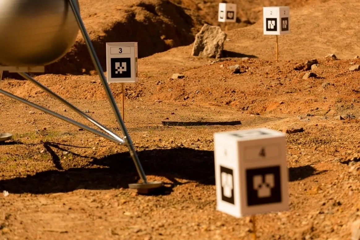
Looking ahead, these wheels will undergo further terrain testing as we prepare for the ERC. But regardless of the competition outcome, we’ve already succeeded in building a component that meets technical requirements, was delivered through professional channels, and taught us lessons most engineers only learn in the field.
What would you have done differently? Have you ever tackled a design like this—where performance depends entirely on geometry and materials? Share your insights below!
Share Your Engineering or Product Design Story

Share Your Story!
Share your engineering and product design journey and get a €300 reward! Showcase your innovative solutions and best practices with our community.
Share Your Engineering or Product Design Story
- We’re looking for stories about innovative mechanical engineering solutions, the design and development of mechanical components, or the creation of cutting-edge hardware products.
- Our team will assist you in preparing your story and translating it into several languages.
- Plus, you’ll receive a reward of 150 EUR to be redeemed with Xometry after your story is published*.


Comment(0)