PolyJet is a photopolymer-based 3D printing technology that jets and cures tiny droplets of resin layer by layer using UV light. It excels at producing highly detailed, accurate parts with sharp edges, smooth finishes, and complex geometries—including full-colour and multi-material assemblies in a single build.
This makes PolyJet ideal for visual prototypes, ergonomic models, medical guides, and fit-check assemblies where tactile realism or fine texturing matters.
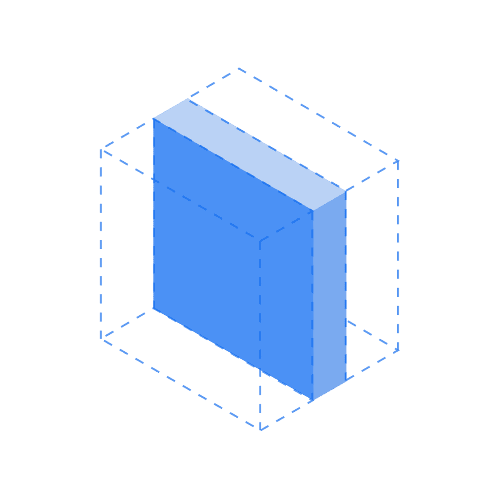
1. Set Wall Thickness and Feature Size for Reliable Prints
Thin walls warp or crack during support removal, especially if unsupported. Similarly, undersized features often fail or print distorted, reducing function and appearance.
Rule of Thumb:
- Minimum wall thickness: 1 mm (supported), 1.5 mm (unsupported); increase to 1.5–2 mm in load-bearing or flex-prone areas to prevent cracking
- Minimum feature size: 0.5 mm
2. Leave Enough Clearance for Pre-Assembled and Moving Parts
PolyJet can print complex assemblies in one piece—but without proper clearance, parts may fuse during printing. This is especially important for ball joints, hinges, and interlocking features. Use generous spacing unless the design is strictly static or lightly loaded, and always test with prototypes before final production.
Rule of Thumb:
- Minimum clearance between assembled parts: 0.5 mm
- Clearance for moving parts: 0.5 mm
- Add alignment features (e.g. dowel pins, slots) for precise fit
- Use snap-fit features only when you can maintain ±0.1 mm accuracy—otherwise, opt for post-assembly fasteners

3. Split Large Assemblies into Joinable Sections
PolyJet’s maximum build size is 490 × 391 × 200 mm. Split larger parts for separate printing and post-assembly, and use mechanical features—like dovetails, puzzle cuts, or interlocking tabs—to improve alignment and joint strength.
Plan for assembly early: allow clearance for bonding, and place splits in low-stress, hidden zones to preserve strength and finish. Use CAD sectioning tools to create puzzle joints and align with dowel pins or slots.
Rule of Thumb:
- Assembly clearance: 0.5 mm between mating parts to avoid fusion
- Add alignment features (e.g. dowels, slots, tabs) to aid positioning
- Use joining strategies like dovetail joints, puzzle cuts, or tongue-and-groove
- Choose bonding or friction fit based on part size, load, and accuracy
4. Include Escape Holes to Prevent Trapped Resin
Trapped resin causes defects and waste. To avoid this, design escape holes that allow trapped resin to drain during post-processing. For long or deep sections, add access points or removable sacrificial parts to ensure clean interiors.
Rule of Thumb:
- Add escape holes for enclosed volumes deeper than 50 mm
- Use hole diameters of 2–4 mm for effective drainage
- For functional pin holes, use a minimum diameter of 2 mm
- For non-functional features, avoid holes smaller than 0.5 mm
- Add removable sacrificial rods or tabs in deep cavities to ease cleaning
5. Add Fillets to Reinforce Thin or Sharp Features
Sharp internal corners and thin junctions are stress concentrators that can lead to cracks or delamination—especially during support removal or handling. Adding fillets reduces these weak points, distributes stress more evenly, and improves structural integrity.
This is especially important for thin-walled parts or intersecting geometries.
Rule of Thumb:
- Use a fillet radius of 0.5–1.5 mm depending on part size
- Round all internal corners with ≥0.5 mm fillets to prevent stress cracks
- Add support structures for overhanging fillets to avoid sagging during printing
6. Size Embossed and Engraved Details for Readability
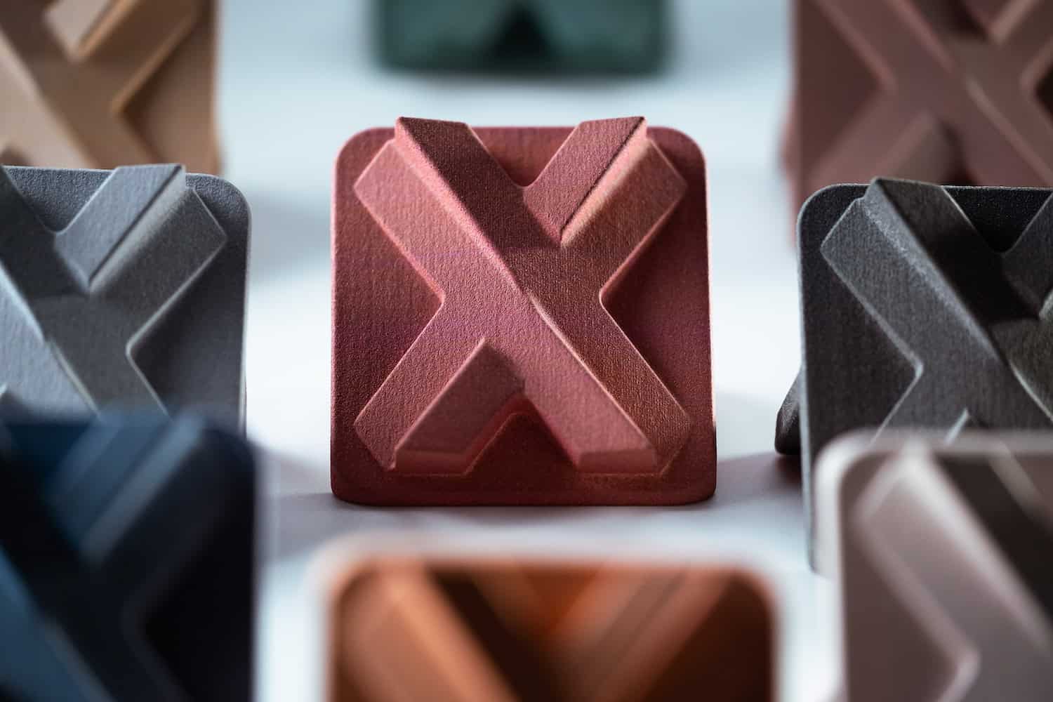
PolyJet allows for fine surface details like logos, text, and patterns—but without proper sizing, they may print poorly or disappear during post-processing.
Sanding or support removal can blur or erase shallow features, so always size them with enough depth or height for visibility.
Rule of Thumb:
- Use sans-serif fonts for best legibility
- Minimum line thickness: 0.5 mm
- Engraved text depth: 0.5 mm
- Embossed text height: 0.5 mm (with minimum thickness of 0.8 mm)

7. Use Hollowing Strategies to Reduce Material Usage
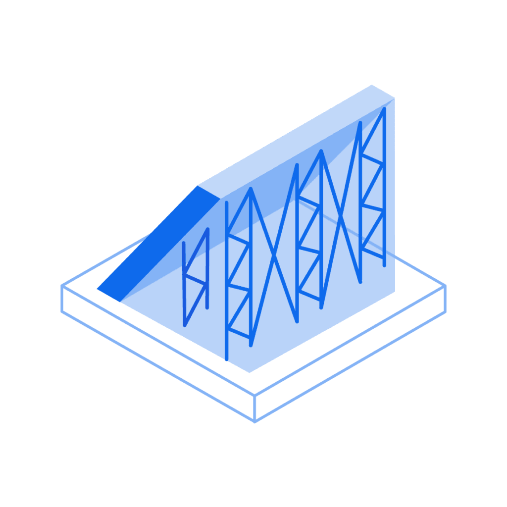
Hollow parts to reduce weight and material use—especially for large aesthetic parts or visual prototypes—while keeping strength and appearance. Hollow only non-load-bearing functional parts. Keep solid areas around fasteners and stress zones.
Use ribs, internal supports, or lattices to reinforce hollow sections. Always include drainage holes to let uncured resin escape, and position them at the lowest point of the part during printing.
Rule of Thumb:
- Add drainage holes (2–4 mm) to release trapped resin
- Place drainage holes at the lowest point on the build
- Use ribs or lattices to support large internal cavities
8. Support Overhangs and Free-Floating Features Strategically
PolyJet prints with a gel-like, water-soluble support material that washes away after printing—but unsupported features can still sag or deform. Overhangs steeper than 45° typically need support, as do floating elements and horizontal bridges.
Minimise the need for support by optimising part orientation and designing self-supporting features where possible. Limit support contact to ≤1 mm² per point to reduce surface blemishes.
Rule of Thumb:
- Support overhangs >45° and floating features
- Use minimal contact points (e.g. teardrop shapes) to reduce marks
- Orient flat surfaces horizontally and tilt overhangs <45° toward the base to minimise support needs
- Use denser supports for heavy or complex features; lower density for small details

PolyJet 3D Printing Specifications Reference Guide
Use the values below as a reference when preparing parts for printing—going beyond them can lead to deformation, fused features, or lost detail.
| Feature | Value |
| Maximum build size | 490 × 390 × 200 mm |
| Minimum feature thickness | 0.5 mm |
| Suggested minimum wall thickness | 1 mm |
| Layer thickness | 16–30 µm, depending on the material |
| General tolerance | ±0.1 mm for the first 25 mm is typical, plus ±0.05 mm for each additional 25 mm. Tolerances may change depending on part geometry. |
Get Your High-Quality PolyJet 3D-printed Parts at Xometry
Mastering PolyJet design unlocks the ability to create smooth, highly detailed, multi-material parts with exceptional precision. By applying the tips in this guide—controlling wall thickness, sizing features correctly, managing supports, and planning for assemblies—you’ll reduce print errors and produce consistent, high-quality results.
Ready to bring your designs to life with unmatched accuracy and surface quality? Partner with Xometry for expert guidance and fast, reliable PolyJet 3D printing tailored to your exact needs.
 Europe
  Türkiye
  United Kingdom
  Global

 Login with my Xometry account
  0
0




Comment(0)