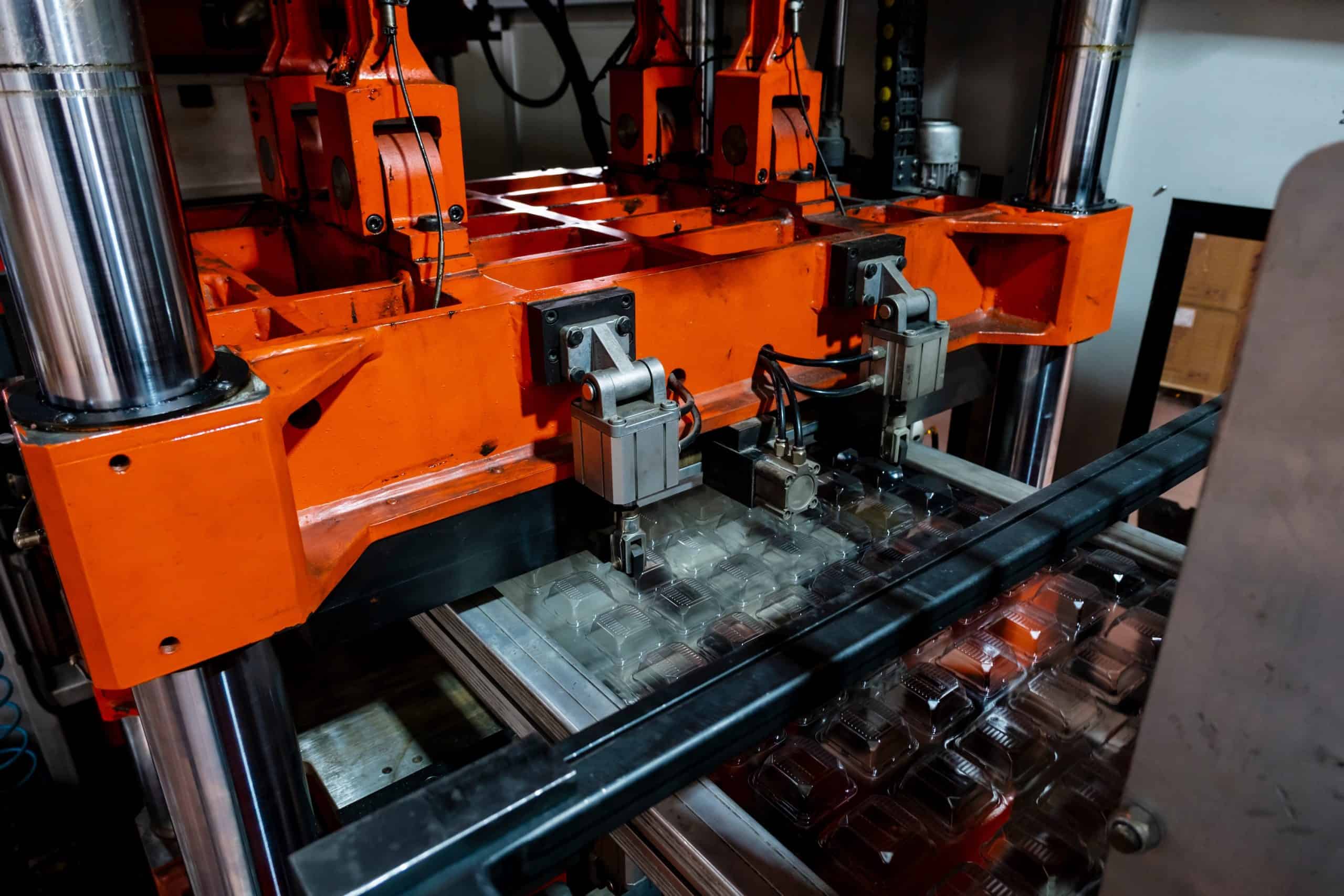
Overmoulding is a versatile manufacturing process that bonds a thermoplastic to a rigid plastic substrate using injection moulding equipment. This method delivers a powerful combination of aesthetics, haptics, and functional performance, providing benefits like superior grip, shock absorption, impact resistance, enhanced surface protection, and better chemical insulation for an improved tactile experience.
A key advantage of overmoulding is its ability to seamlessly fuse multiple materials into a single, durable component through mechanical or chemical bonding. This technique is perfect for projects requiring customised designs, flexibility, or enhanced functionality, and reduces manufacturing costs by consolidating parts into a single, integrated component.
Quick Reference Guide
The table below provides a concise overview of the key technical details, materials, and benefits of overmoulding.


Types of Overmoulding Techniques
The following is a brief description of the four predominant methods used in overmoulding:
- Rigid plastic over metal: A metal component acts as the substrate, and plastic is moulded around it. The metal piece, which could be cast or CNC-machined, is placed in a mould, and molten plastic is injected around it. This method, often applied in insert/transfer moulding is ideal for creating parts that require the strength of metal with the aesthetic finish of plastic, such as handles and knobs.
- Elastomer over rigid plastic: An elastomer layer is moulded over a plastic core, creating a softer surface to improve comfort and grip. It is typically achieved through two-shot overmoulding, where two materials are injected sequentially in the same mould. Common applications include power tool handles, grips, and buttons, providing a durable yet cushioned feel even under pressure.
- Rigid plastic over rigid plastic: Both the substrate and the overmoulded material are plastics. Typically, plastics with similar melting points are paired to ensure strong bonding. Examples include children’s toys with soft handles or multi-colored finishes.
- Elastomer over metal: A metal substrate is coated with an elastomer, combining the structural strength of metal with the resilient, soft-touch properties of an elastomer. This combination is ideal for tools and products requiring both durability and a comfortable, secure hold.

Why Choose TPEs for Overmoulding Applications?
Thermoplastic elastomers (TPEs) are ideal for overmoulding due to their flexibility, durability, and ability to bond effectively with various rigid plastics, like ABS and polycarbonate. Combining the softness and impact resistance of rubber with the ease of processing of thermoplastics, TPEs enhance product ergonomics, grip, and aesthetics. This consolidation of parts reduces assembly steps and cuts manufacturing costs.
Common TPE materials suitable for overmoulding include Thermoplastic Polyurethane (TPU), known for its high elasticity and abrasion resistance, and Thermoplastic Vulcanizate (TPV), which offers strong chemical resistance and flexibility for automotive and sealing applications.
Materials Selection for Overmoulding
While TPEs like TPU and TPV are widely favored for overmoulding due to their flexibility, durability, and strong bonding capabilities, other materials such as Nylon, Polypropylene (PP), and Polycarbonate (PC) are also popular choices for specific applications. The table below compares these commonly used overmoulding materials, highlighting their unique properties and advantages.
| Overmoulding Material | Common Applications | Properties | Compared to TPEs | Suitable Overmoulding Techniques |
| Thermoplastic Polyurethane (TPU) | • Handles • Grips • Automotive components |
• High elasticity • Excellent abrasion resistance • Strong bonding capabilities |
– | • Elastomer over rigid plastic • Elastomer over metal |
| Liquid Silicone Rubber (LSR) | • Medical devices • Kitchen utensils • Seals |
• Heat-resistant • Flexible • Biocompatible • Suitable for high-temperature applications |
More heat-resistant and biocompatible than TPEs, but less flexible and not as easy to bond with rigid plastics | • Elastomer over rigid plastic • Elastomer over metal |
| Thermoplastic Vulcanizate (TPV) | • Seals • Gaskets • Automotive parts |
• Good chemical resistance • Elasticity • High-temperature resistance |
– | • Elastomer over rigid plastic • Elastomer over metal |
| Nylon (Polyamide, PA) | • Overmoulded metal parts • Automotive parts |
• High strength • Rigidity • Resistance to wear • Suitable for bonding with softer materials |
Higher strength and wear resistance, but lacks flexibility and softness | • Rigid plastic over metal • Rigid plastic over rigid plastic |
| Polypropylene (PP) | • Packaging • Consumer products |
• Low cost • Good chemical resistance • Flexible |
More affordable, but generally less durable, flexible, and with less bonding capability | • Rigid plastic over metal • Rigid plastic over rigid plastic |
| Polycarbonate (PC) | • Electronics housings • Lenses |
• High impact strength • Heat resistance • Transparency • Suitable for rigid overmoulding |
Better impact strength and transparency, but lacks the softness and grip-enhancing properties | • Rigid plastic over metal • Rigid plastic over rigid plastic |
Material Matching and Compatibility
Selecting the right combination of substrate and overmoulding material is crucial to achieving a strong bond and ensuring product performance. Different substrates, such as polycarbonate or polyamide, each have unique properties that influence their compatibility with overmoulding materials like TPEs.
The table below provides a comparison of common substrates, their key characteristics, and their bonding compatibility with TPEs:
| Substrate Material | Properties | Compatibility with TPEs | Bonding Difficulty |
| ASA | • UV-stable • Weather-resistant • Used in outdoor applications |
• Good compatibility with TPEs • Ideal for outdoor applications where both flexibility and durability are important |
Easy |
| ABS | • Versatile • Rigid thermoplastic • Good impact resistance • Used in automotive and electronics |
• Bonds well with TPEs • Useful in applications requiring impact resistance and toughness |
Easy |
| PA (Polyamide) | • Strong • Wear-resistant • Used in automotive, industrial, and consumer products |
• Requires specific TPEs for adequate bonding. • Polyamide’s high moisture absorption can interfere with the bonding process by weakening the adhesive interface between the polyamide and TPE. This makes careful material selection and drying of the polyamide before moulding essential |
Moderate |
| PET | • Strong • Lightweight • Often used in packaging and textiles |
• Moderate bonding with TPEs. • Pre-treatment may improve adhesion |
Moderate |
| PMMA | • Clear • Rigid plastic • Used for optical applications |
• Has limited compatibility with certain materials, particularly TPEs, which may require surface treatment to enhance adhesion. • Surface treatments such as plasma or corona treatment can improve bonding by increasing the surface energy of PMMA |
Difficult |
| PC (Polycarbonate) | • Tough • Transparent • Used for impact resistance |
• Bonds well with certain TPEs | Easy |
| PP | • Lightweight • Chemical-resistant • Moisture resistant • Used in automotive parts like bumpers and interior trim, as well as in packaging |
• Challenging to bond without surface treatment | Difficult |
| PK (Polyketone) | • High-performance alternative to PA • Superior chemical resistance |
• Challenging to bond; not all TPEs adhere well | Difficult |
Chemical compatibility in overmoulding is essential to achieving strong, durable bonds between materials, ensuring product reliability, resistance to stress, and long-term performance. The chart below provides a comprehensive overview of material compatibility for overmoulding processes, showing how different softer materials can bond effectively with harder substrates.
Top 10 Rules for Creating Overmoulded Components
The following top 10 rules provide essential guidelines to optimise the overmoulding process and ensure consistent performance and durability of the final components.
- Match material chemistry: Ensure that the TPE and the substrate are chemically compatible to achieve strong and durable bonding.
- Ensure TPE thickness: Maintain a minimum TPE thickness of 1mm to promote adequate bonding, and use mechanical interlocks for thinner areas.
- Balance substrate and TPE thickness: Keep the substrate thickness at least twice the TPE thickness to minimise warping and maintain structural integrity.
- Optimise flow ratios: Maintain flow length-to-thickness (L/T) ratios between 80:1 and 120:1 for new component designs to improve material flow and adhesion.
- Select appropriate gate size: Choose a gate size based on the TPE type and thickness, starting with smaller gates to control material flow effectively.
- Incorporate venting: Add air vents of 0.01 to 0.02 mm along the perimeter or at the end of the fill to prevent air traps and ensure smooth flow.
- Implement effective shut-offs: Design precise flow shut-offs to prevent material flashing and maintain clean part surfaces.
- Use balanced runner systems: For large or multi-cavity parts, utilise a balanced runner system or hot runner to maintain uniform flow and consistent bonding quality.
- Add surface texture: Use textured mould surfaces to prevent sticking and mask aesthetic imperfections for a more refined finish.
- Design for ejection: Utilise rigid substrate surfaces for easier ejection of overmoulded components from the mould.
Key Design Considerations in Overmoulding
Effect of Flow Length/Thickness Ratio (L/T) on Bonding Strength
The flow length/thickness ratio (L/T) helps achieve strong bond adhesion in TPE-substrate combinations.
- Melting temperature: The melting temperature of the overmould and substrate materials affects the L/T ratio, which in turn affects bonding strength.
- Recommended L/T Range: When the L/T ratio falls outside the range of 80-120:1, the overmoulded product may fail to produce sufficient bond strength.
- High L/T ratios: If the part overmoulding geometry results in L/T ratios greater than 120:1, multiple feed gates are recommended for the overmould material to prevent weak bonding due to insufficient flow from molten material from a single inlet.
- Wall thickness: Use a minimum TPE wall thickness of 1.016 mm to create adequate bonding. For thinner areas of bonding, use TPE interlocks to improve adhesion.

TPE Shrinkage and Component Design
TPE shrinkage contributes to the appearance of overmoulded parts. Please add the metrics equivalent
- Shrinkage values: TPEs generally exhibit shrinkage values ranging from 0.051 mm to 0.356 mm per inch, whereas other thermoplastic base materials shrink between 0.0.051 mm to 0.356 mm per inch. This difference in shrinkage can lead to warpage or misalignment.
- Thickness recommendations: Substrate thickness should be at least double the TPE thickness to reduce the likelihood of warping.
- Ribbing caution: In TPE overmoulding, ribbing can sometimes act as a heat sink, causing uneven cooling and potentially affecting the part’s quality. To avoid issues like warping or weak spots, carefully design ribs and, if necessary, reduce or modify them in areas prone to defects like melting or suction marks. If ribbing is essential for strength, adjust the cooling process.
- Curling: Curling can occur when TPE extends beyond the edge of the substrate, potentially leading to wrinkling in the overmould. Proper substrate design and support near the edges help minimise this issue by providing a stable surface for the TPE to adhere to.

Shut-Off Design
A properly designed shut-off prevents TPE flash in overmoulding.
- Shut-off grooves: Incorporate shut-off grooves into the mould design to prevent flash and allow air to vent from the TPE overmoulding area. This dual-purpose design ensures a tight seal to block excess material and provides channels for air to escape.
- Tool steel penetration: Tool steel, a type of high-carbon steel, should penetrate the substrate by about 0.0762–0.1016 mm to achieve effective shut-off and prevent flash formation.
- Venting via shut-off grooves: While shut-off grooves can assist in venting the TPE section by allowing trapped air to escape, caution is needed when placing vents. Directly positioning vents at the shut-off edges can encourage flash formation, as this may create gaps that allow the overmoulding material to seep through.

Effect of Surface Texture on Part Ejection
The mould’s surface texture impacts how easily the overmoulded TPE assembly can be ejected.
- Sticking issues: Polished tool steel surfaces can cause sticking issues with TPEs due to their low surface energy, which increases adhesion between the mould and the TPE. This can make part removal difficult. Other materials, contaminants, mould design features, and moulding conditions can also contribute to sticking problems. Polished surfaces are particularly prone to causing adhesion issues with TPEs.
- Recommended texture: Establish the maximum and minimum surface roughness specifications. A sandblasted finish or light electro-discharge machining texture should not exceed a depth of 0.0254 mm. In contrast, critical sections like runners and gates should feature a rougher texture ranging from 0.0762 to 0.1016 mm to promote material flow while minimising adhesion.
- Use of release coating: Apply nickel-PTFE release coating over the texture to prevent sticking.
Gate Size and Runner System Design
Gate size and runner system design are critical in overmoulding, ensuring proper flow, uniformity, and effective bonding of materials:
- Gate size: The gate size should be appropriate for the flow characteristics of the TPE type and thickness. Start with a smaller gate size to control the flow and adjust as needed for the specific material properties.
- Runner system uniformity: For large, multi-cavity parts, a balanced runner system or a hot runner should be used to ensure even flow and effective bonding across different components. This uniformity is crucial to achieving consistent part quality and optimal bonding.
Overmoulding vs. Insert Moulding
Overmoulding involves using two normally distinct materials by moulding an additional layer on top of the base material, while insert moulding is a manufacturing process that involves placing pre-formed inserts—typically made from materials like metal or plastic—into a mould cavity. The table below is a compendium of the most important aspects of overmoulding and insert moulding technologies:
| Factor | Overmoulding | Insert Moulding |
| Process | Involves injecting two shots of materials to form a substrate and overmould | Uses a single shot around pre-placed inserts |
| Design Considerations | The overmould should be thinner than the substrate to ensure proper adhesion and prevent issues like cracking or peeling. Material compatibility achieves a successful bond between the overmould and the base material. | Preheat the inserts before the moulding process to enhance adhesion and prevent thermal shock. Using knurled surfaces on inserts can improve mechanical interlocking with the injected plastic. Consider material shrinkage to prevent cracking during cooling. |
| Ideal Applications | Products needing a comfortable grip, vibration absorption, electrical insulation, or enhanced aesthetics | Products requiring strong mechanical fittings durable threads, or components like electrical connectors, parts with pre-formed metal components or electronics |
| Design Flexibility | Allows for multi-material design with contrasting colors and textures; can improve appearance and functionality | Offers versatility in integrating metal and plastic, but with fewer design options compared to overmoulding |
| Strength & Durability | Creates a permanent bond between the materials but is more effective for adding features like grips or cushioning | Provides high strength and durability, especially with metal inserts |
| Cost | Generally more expensive due to the need for specialised moulds and multiple injection cycles | While insert moulding can be cost-effective by combining steps, the need for manual insertion in some scenarios can influence overall costs |
| Production Complexity | Requires more complex tooling and additional steps, making it slower and more labor-intensive | Requires precise positioning of the inserts which can sometimes involve manual labor, especially for complex designs or low-volume productions. |
| Typical Drawbacks | Requires specialised equipment and longer production times; some elastomers may not adhere well to certain substrates | Precise positioning of the inserts is critical to ensure they are correctly placed before the plastic is injected. |
| Materials | Typically uses two materials: a harder base substrate (plastic or metal) and a softer elastomer (TPE/TPU) | Metal inserts, such as screws or other components, are placed in a mould, and plastic resin is injected around them. This process “glues” the insert into the plastic, creating a solid bond and a single piece. This integrates different materials, enhancing the mechanical properties and functionality of the final product. |
Key Insights for Effective Overmoulding
Overmoulding is a versatile manufacturing technique that combines materials to improve features like grip, chemical resistance, and aesthetics, making it ideal for power tools, medical devices, and automotive parts. Key factors for success include ensuring material compatibility, bonding strength, shrinkage control, and proper venting.

While overmoulding integrates materials seamlessly, alternatives like adhesive bonding can be better for chemically incompatible materials or flexible connections, ideal for lightweight or intricate products. Mechanical fastening offers strong, detachable joints, making it suitable for heavy components or parts requiring maintenance. These methods can reduce complexity and allow easier disassembly or adjustments.
When overmoulding isn’t feasible, have you explored alternative methods like adhesive bonding, mechanical fastening, or co-moulding? What were the key factors in your decision, and how did these methods impact your product design or manufacturing efficiency?
 Europe
  Türkiye
  United Kingdom
  Global

 Login with my Xometry account
  0
0


Comment(0)