 Europe
  Türkiye


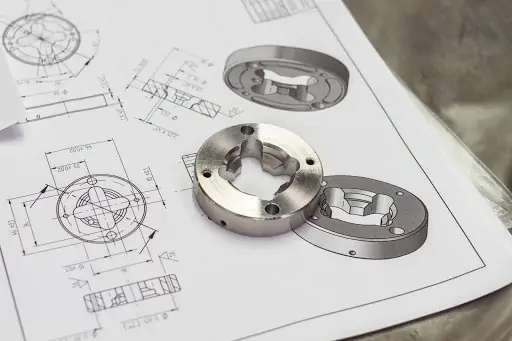
Depending on the manufacturing process, machinery, operator skill, and other factors, parts will always deviate from nominal dimensions. Problems often appear at assembly: features don’t fit or function as intended, or they do, but with extra friction or slack that can significantly reduce part life.
Thus, engineers turn to tolerancing. Dimensional tolerances are the most common way to limit inaccuracies. Most engineering drawings state a general tolerance class that applies to all dimensions unless otherwise specified.
However, dimensional tolerances alone don’t reflect the intended function of the part, leaving many critical feature behaviors unspecified.
What Is GD&T? And Why Use It?
Geometric Dimensioning & Tolerancing (GD&T) provides a complete language to ensure functionality by defining both feature size and geometry.
GD&T is a standardized way to communicate not just size, but also shape, location, and alignment so a part works exactly as intended. It lets engineers convey design intent to manufacturing and inspection teams for a uniform understanding that maximizes the probability of project success.
Key benefits:
- Clear communication – Symbols make it obvious which features matter for function, removing guesswork between design, machining, and inspection.
- Controls what matters – Unlike basic dimensions, GD&T covers size, location, orientation, and form.
- Interchangeability – Parts from different batches or suppliers still assemble and function properly.
- Cost savings – Tighten tolerances only where needed, reducing scrap and avoiding delays from unfit deliveries.
- Consistent inspection – Defines exactly how to measure, reducing disputes and preventing bad parts from slipping through.
- Flexibility when possible – Material condition modifiers like MMC/LMC can provide bonus tolerance when part size allows.
In short, GD&T makes drawings more functional, reduces misunderstandings, and can save both time and money—when you apply it only where it’s truly needed.
| Name | Description | When to Use | Drawing Examples |
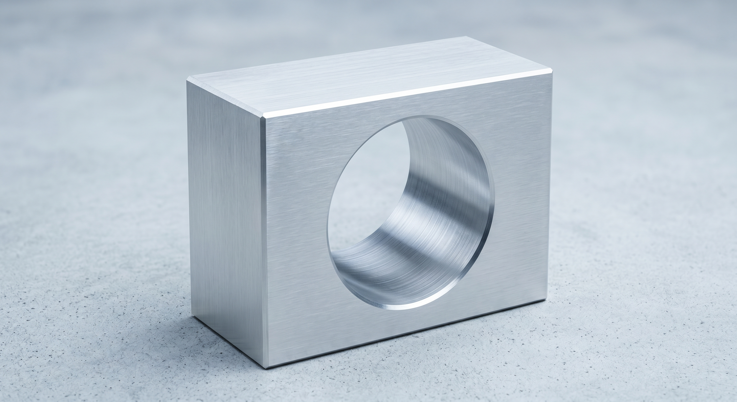
| Flatness | All surface points must fall between two parallel planes. (No datum.) | Mating/sealing faces need even contact; fixtures need stable seating. | Base plate surface lies flush on the granite table without rocking. |
| Straightness | Axis deviation limited inside a small cylindrical zone. (Feature of size.) | Guide shafts/spindles need true axes for smooth motion and low wear. | Long shaft runs within straightness limits—no mid-span bow. |
| Cylindricity | Entire cylindrical surface must fit a single coaxial tolerance cylinder. | Rotating/press-fit cylinders must run true along their length. | Bearing journal conforms to one coaxial cylinder along its full length. |
| Circularity (Roundness) | Every cross-section must fit between two concentric circles. (No datum.) | Isolated round sections need uniformity without building a DRF. | Turned shaft section measures uniformly round at every angle. |
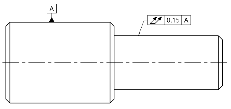
| Parallelism | Surface/axis oriented parallel to the datum within a defined zone. | Opposed faces/axes must track together to avoid tilt or pinch. | Top face of a machined block remains parallel to the bottom datum face. |
| Perpendicularity | Surface/axis oriented 90° to the datum within a defined zone. | Bores to seats; square load paths; accurate alignments. | Milled edge is square (90°) to the datum surface. |
| Angularity | Surface/axis oriented at a specified basic angle (≠90°) to a datum. | Non-right-angle features critical to meshing/flow/assembly. | Chamfer held at 45° relative to the base datum. |
| Position | Locates an axis/center at true position (cylindrical zone; uses datums). | Patterns/pins/bores must assemble reliably across suppliers. | Flange bolt-hole centers located at their true positions on the pattern. |
| Concentricity | Median points align to a datum axis. | Mass-center alignment for balance—usually replace with position/runout. | Stepped shaft’s small diameter shares the same center as the pilot bore. |
| Symmetry | Feature midplane centered on a datum plane. | Keep equal clearance/load on both sides of a midplane. | Forked slot walls are equally spaced about the center plane. |
| Profile of a Surface | Entire surface must lie within a 3D tolerance band. | Freeform/compound faces must follow CAD for function/aesthetics. | Car-door outer skin follows CAD surface within the profile band. |
| Profile of a Line | Any chosen section must lie within a 2D tolerance band. | Control edge/section smoothness where visual fit matters. | Bumper opening section matches the specified template curve. |
| Circular Runout | Limits section variation during rotation about a datum axis. | Control face “wobble” at each section to reduce vibration. | Brake disc face shows minimal variation over one revolution. |
| Total Runout | Limits full-surface variation during rotation. | Full-length journals/sealing surfaces must run true (NVH, leaks). | Driveshaft journal tracks true along its entire length while rotating. |
| MMC (Maximum Material Condition) | Adds bonus tolerance as the feature departs from max material. | Clearance fits: pins/holes when assembly ease matters but strength is unaffected. | Locating hole at its smallest size permits bonus position tolerance. |
| LMC (Least Material Condition) | Adds bonus tolerance as the feature departs from least material. | Edge distance / wall-thickness protection near holes or cutouts. | Edge-near hole retains minimum wall by using LMC bonus. |
| RFS (Regardless of Feature Size) | No bonus; geometry held regardless of actual size. | Optical mounts, sealing features, precision location despite clearance. | Alignment bore held at position regardless of actual size. |
Overview of the most widely used GD&T symbols with explanations and real-world drawing examples.
Feature Control Frame
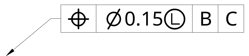
The feature control frame (FCF) carries all information needed by both manufacturing and inspection. It specifies what geometric control applies, how much variation is allowed, and relative to what references.
- The leader arrow – The arrow indicates what surface or feature is affected by the geometric tolerances. Sometimes there’s no leader: the FCF may be placed next to a basic or diametric dimension; in that case, the feature of size is affected.
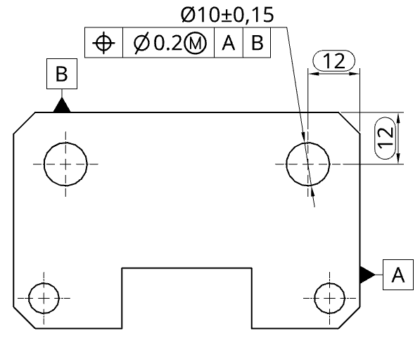
- Geometric tolerance symbol – The first box of the feature control frame defines which geometric tolerance is used, in this case position.
- Feature tolerance -The numeric value is always present (e.g., 0.15 mm). Additional symbols may define the zone shape (e.g., ⌀ for a cylindrical zone). This cell can also include a material condition modifier—MMC (Ⓜ) for Maximum Material Condition or LMC (Ⓛ) for Least Material Condition.
- Datums – The following compartments list the datum references (e.g., |B|C|) that establish how the tolerance is oriented and located.
Datums
A datum is a theoretically exact reference, used to measure and verify geometric controls in GD&T. Because real parts and fixtures are never perfect, GD&T distinguishes between datum features, datums, and datum simulators:
- Datum feature – The real surface/edge/axis on the part that you designate as a reference (e.g., a machined face, a bore axis). It has imperfections.
- Datum – The ideal, perfect reference derived from the datum feature (e.g., a mathematically perfect plane or axis).
- Datum simulator – The physical device that acts like the datum during inspection or setup (e.g., a surface plate, pins, V-blocks). The datum feature is brought into contact with the simulator to establish the measurement setup.
This has direct implications for inspection results. Many FCFs reference more than one datum; the order of datums in the FCF defines how the coordinate system is built—this is the datum reference frame (DRF) used for measurement.
Building the DRF (A–B–C):
- Primary datum (A) – Establishes the first reference plane/axis; requires at least three points of contact.
- Secondary datum (B) – Adds orientation/location constraint; at least two points of contact.
- Tertiary datum (C) – Final constraint; at least one point of contact.
Changing the A–B–C order changes how the part is constrained on the simulator and can change inspection results. Choose datums—and their sequence—to match functional assembly and actual inspection setups.
GD&T Categories
Geometric dimensioning and tolerancing is divided into 5 distinct categories:
- Form – Control the inherent shape/consistency of features without referencing datums.
- Flatness
- Straightness
- Cylindricity
- Circularity
- Orientation – Control the tilt or alignment of a feature relative to a datum. Require at least one datum as reference.
- Parallelism
- Perpendicularity
- Angularity
- Location – Position a feature’s axis, center plane, or center point precisely by referencing datums. These datums act as a coordinate system, establishing the permissible deviation of a feature from its true position or true location. This ideal, intended position is defined by basic dimensions, which are standard linear dimension lines.
- Position
- Concentricity (stripped from ASME)
- Symmetry (stripped from ASME)
- Profile – Control 2D/3D outlines relative to datums for proper alignment.
- Profile of a surface (3D)
- Profile of a line (2D)
- Runout – Controls surface variation as a part rotates around a datum axis. It is unique in that it checks both geometry and alignment, and is commonly used to prevent vibration in components such as axles and shafts.
- Circular runout
- Total runout
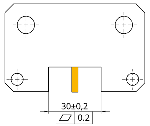
Flatness (Form)
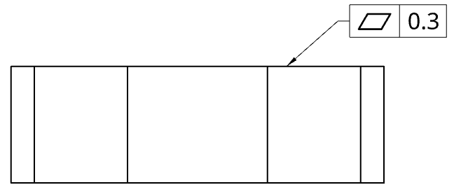
The flatness tolerance defines a zone between two parallel planes. The zone’s thickness is indicated in the feature control frame. To meet the requirements, all points on the surface must remain within the tolerance zone.
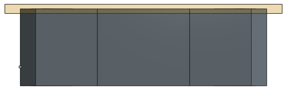
Flatness is often used when a face must mate with another part to ensure even contact. It can also be applied to features of size (anything with a measurable size like a cutout). In that case, the two-plane zone is formed through the middle of the measured feature.
Geometric dimensioning and tolerancing (GD&T) is typically applied to parts and features requiring precise, often imperceptible tolerances, particularly in machining. However, flatness tolerance has broader applications. For instance, in large-scale sheet or tube cutting, laser heating can lead to visible bends, making flatness a critical consideration.
So when doing a lot of cutouts on a 120x60x6000 mm rectangular tube, it can end up curved like a banana. Defining the tolerance zone is simple to do and simple to measure, as you just have to lay down the tube and measure its highest point to see whether it fits the tolerance zone or not.
Flatness vs. surface roughness: Flatness addresses overall shape (macro), surface roughness addresses texture (micro). A surface can be flat but rough, or warped but smooth.
Use example: When two faces will mate and need evenness: a valve body sealing face to prevent leaks.
Straightness (Form)
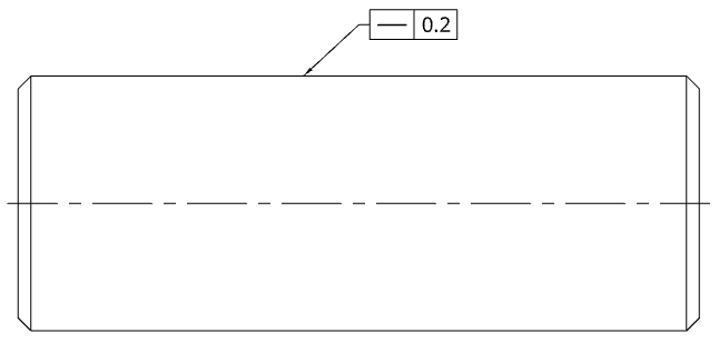
Straightness is the same tolerance as flatness, minus one dimension. Meaning the tolerance zone is 2D instead of 3D.
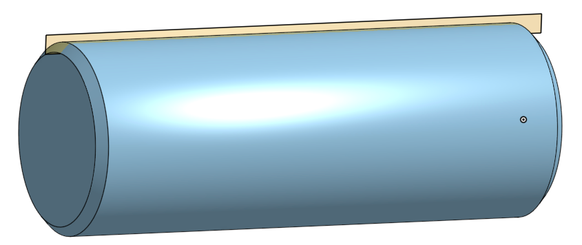
A simple way to think about straightness is through measurement: a coordinate measuring machine (CMM) moves in a single straight line on a surface, checking if all points on that line fall within the tolerance zone. On a cylindrical part, you can draw many parallel lines to measure. Note: all lines can individually pass while there is still dislocation between lines not checked.
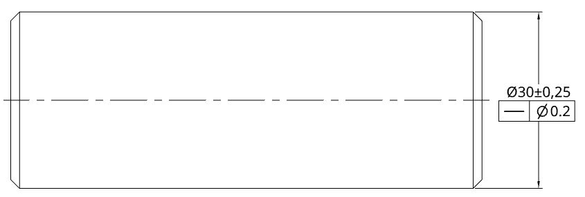
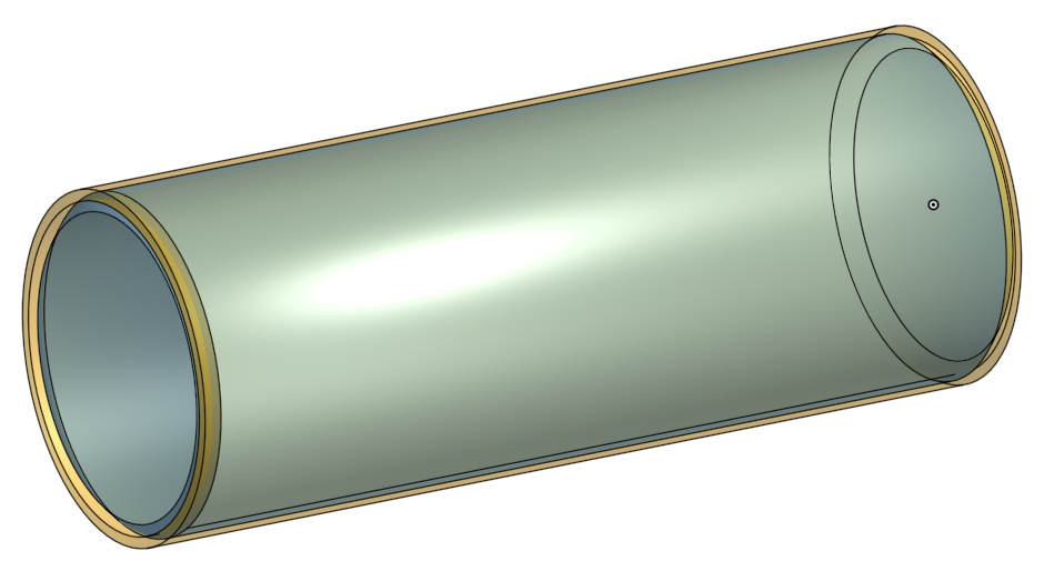
When straightness is applied to a feature of size (e.g., a shaft diameter), it creates a cylindrical zone around the axis. The axis (or derived median line) must lie within that zone along the length. The same applies to a hole axis.
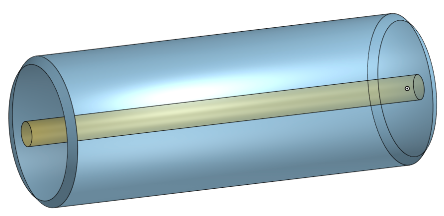
Use example: Where something must be really straight to fit or seal well: a CNC guide rail for smooth motion.
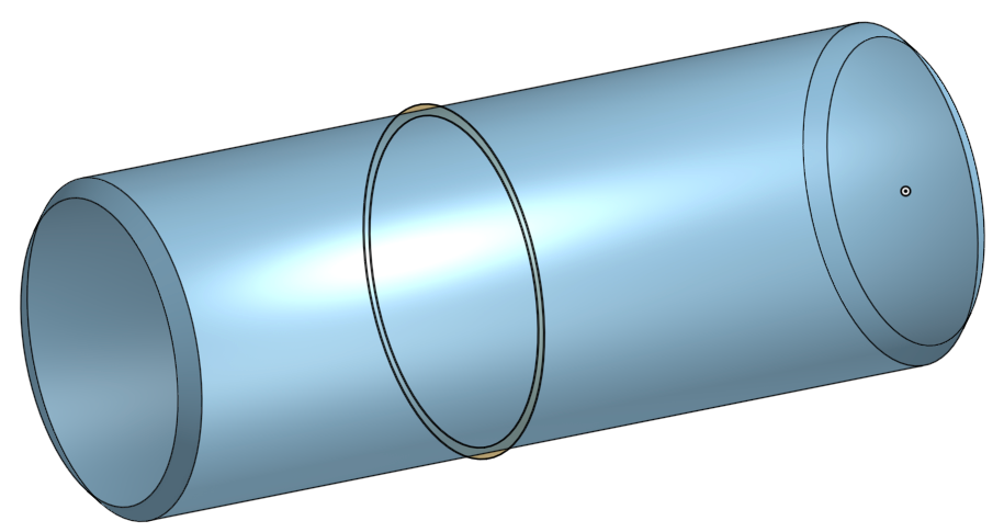
Cylindricity (Form)
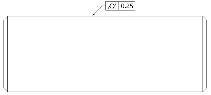
Cylindricity defines a tolerance zone that is uniformly surrounding a cylinder, pin or hole feature. Every point on the feature surface must fall within the zone.
In essence, cylindricity is a 2-in-1 control that encompasses circularity (roundness at each cross-section) and straightness (no axis wander) along the entire length.
Use example: A high-speed motor shaft that must be straight and round along its length to minimize imbalance.
Circularity (Form)
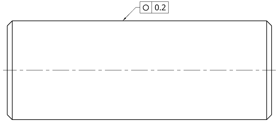
Circularity (roundness) controls the roundness of a single cross-section. The zone is two concentric circles; there is no length component. Circularity is to cylindricity what straightness is to flatness. The tolerance zone’s width is again determined by the numerical value in the control frame.
Because circularity applies section by section, the part may have different cross-section diameters with no issue; each section has the same zone width but a different nominal.
Use example: A bearing seat that must be round for even load distribution.
Parallelism (Orientation)
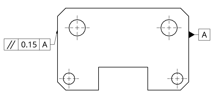
Parallelism states that a surface (or axis) must be parallel to a datum within a specified tolerance zone. In CAD you pick a reference and get perfection; in GD&T you define a measurable tolerance zone about that ideal.
Use example: Two surfaces or axes must be parallel for function: the rails of a linear actuator.
Perpendicularity (Orientation)
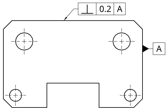
Perpendicularity controls a feature or plane at 90° to a datum feature. Although the nominal is an angle, the tolerance is given in linear units (e.g., mm).
Use example: Alignment or load transfer requires near-perfect perpendicularity: a cutting tool holder bore relative to the holder base to avoid misalignment.
Angularity (Orientation)
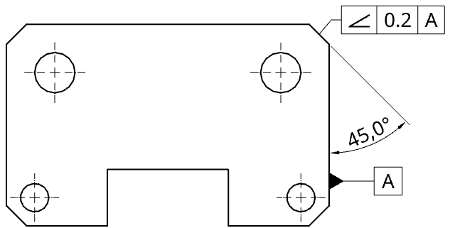
Similar to perpendicularity, but the angle to the datum is not 90°. The nominal angle is defined by a basic dimension (e.g., 45°); the angularity tolerance provides linear room for error. This is often more practical for inspection with CMMs or gauges than a pure angular tolerance.
Use example: A specific angle between planes is required: a gear tooth face angle for proper meshing and load distribution.
Position (Location)
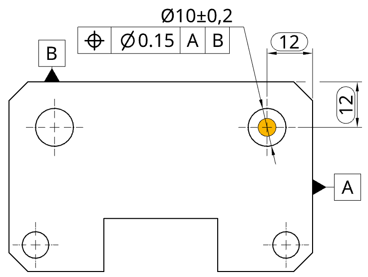
Position is one of the most used GD&T controls. Instead of rectangular tolerance “boxes” from linear dimensions, position defines a cylindrical tolerance zone centered at the true position (from basic dimensions).This allows you to control not only where a feature (e.g., a hole axis) is, but also to ensure it is properly oriented to the referenced datums.
Basic dimensions (boxed) establish the true position; the position control defines the allowed cylindrical tolerance zone about that true position.
Use example: Exact hole/pin locations critical for assembly: a bolt pattern on a flange for gasket alignment.
Concentricity (Location)
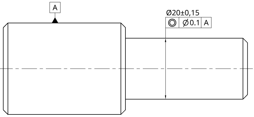
In the most recent revision of the ASME standard, ASME Y14.5-2018, concentricity was removed. This is because its definition can be covered by position tolerance and runout, both of which are more frequently used. However, it is important to note that concentricity is still present in the equivalent family of ISO standards.
Concentricity requires the median points of all diametrically opposed surface elements to fall within a cylindrical zone coaxial with a datum axis. While it can be justified mechanically, it complicates inspection (CMM data-heavy). Often replaced by position and/or runout in ASME workflows.
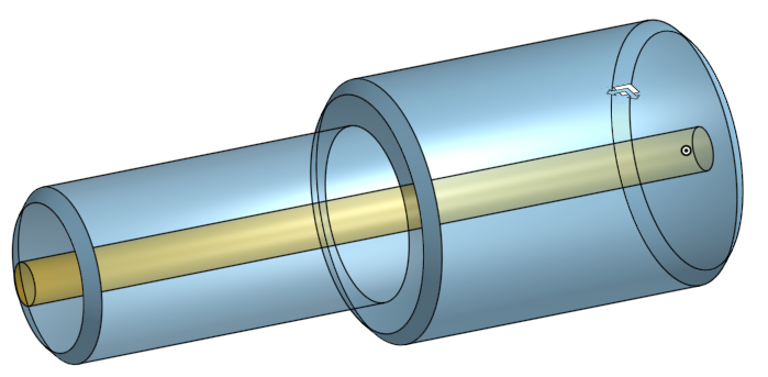
For a stepped shaft with varying diameters, aiming for optimal rotational smoothness. You can designate the axis of one section (e.g., the thicker one) as the datum axis. Then, conceptualize an imaginary cylindrical tolerance tube extending from this datum axis. The key is that all axis points of the shaft’s second section must remain confined within this extended tolerance tube.
Use example: When the mass centerline must align for balance in rotation: turbine shaft sections.
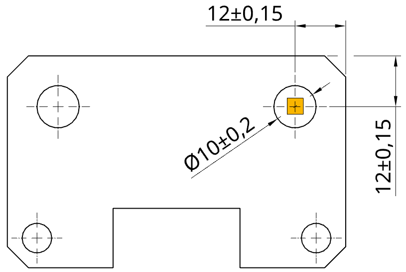
Symmetry (Location)
Similarly to concentricity, symmetry was removed from the ASME standard due to similar considerations, yet it remains a feature in the ISO standard.
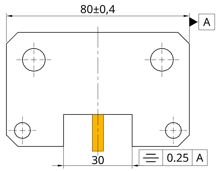
Symmetry requires that the median points of two opposing features must fall within a specified tolerance zone, which is a yellow block centered on a datum plane. In essence, the feature’s center plane needs to align with the datum center plane within a defined tolerance band.
Use example: Equal spacing is important for function or balance: forked mounting surfaces (like the yoke of a universal joint) centered relative to a shaft axis for even load distribution.
Profile of a Surface (Profile)
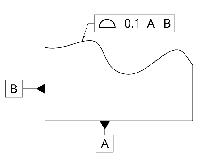
Profile of a surface defines a uniform 3D tolerance zone around the nominal surface (from basic dimensions) and references datums for orientation/location. It’s a similar envelope concept to flatness, but flatness is a form control with no datums, while surface profile supports simple or complex shapes with datum relationships.
The difference is that the profile of a surface is also suitable for more complex shapes, creating a zone where all the points of the surface must lie in. Also, it needs a datum feature for reference.
Use example: Control of freeform/curved surfaces where consistent shape matters: an aerodynamic panel staying within its designed profile for airflow.
Profile of a Line (Profile)
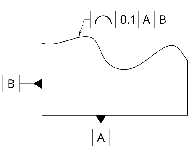
The profile of a line is to surface profile what straightness is to flatness. It specifies the minimum and maximum boundaries for the thinnest cross-section of a surface, effectively disregarding the third dimension.
This approach is useful when you need precise control of a surface’s shape along specific directions without necessarily constraining the entire surface at once.
Use example: Control of the curvature of a car body panel along a section to ensure smooth reflections and consistent assembly gaps.
Circular Runout (Runout)
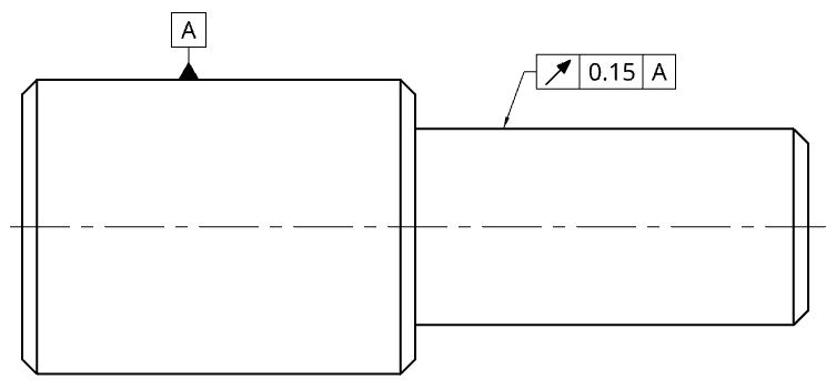
Circular runout defines the roundness of a feature’s individual cross-sections relative to the datum axis. Its tolerance zone, similar to circularity, is delineated by two concentric circles centered on the datum axis.
However, it’s important to note that circular runout is not the same as circularity. In practice, runout is evaluated with the part rotating about the datum axis, while circularity is a static roundness check on a single cross-section.
The similarity to circularity is in the fact that the diameter of the zone may vary at each cross-section, and likely does.
Use example: Rotating parts must remain aligned and balanced: crankshaft journal circular runout relative to the main axis to prevent vibration and uneven bearing wear.
Total Runout (Runout)
Total runout is similar to circular runout but inspects the entire surface of a feature, rather than individual cross-sections, relative to a datum axis. The tolerance zone is cylindrical and spans the feature’s full length.
This control guarantees the surface is both round and straight along its entire axis, not merely at isolated sections.
Use example: Where full-length rotation quality matters. E.g., driveshaft total runout to ensure smooth rotation and avoid drivetrain vibration.
Modifiers
Modifiers are an important part of GD&T. They allow for some additional bonus tolerance for tolerances depending on how close a feature is to its tolerance limits.
Maximum Material Condition
Maximum material condition or MMC for short is a condition whereby the workpiece has the most amount of material left after a cutout has been performed.
For example, if a 10mm hole is specified with a tolerance of +/-0.15mm, the minimum permissible hole size is 9.85mm. This 9.85mm dimension represents the MMC, as it leaves the most material.
When using GD&T positional tolerance without an MMC definition, the hole’s position must simply meet the specified tolerance (e.g., 0.2mm), regardless of its actual size. However, in practical applications, size is often critical, and this can be addressed by applying the MMC modifier.
When the MMC modifier is applied, a “bonus tolerance” is gained if the hole’s actual size is larger than the MMC. For instance, if the hole is 10.1mm, you gain an extra 0.25mm (10.1 – 9.85 = 0.25) of displacement allowance, in addition to the original positional tolerance.
The primary purpose of bonus tolerance is to increase the allowable margin for error, which ultimately helps to reduce manufacturing costs.
Bonus tolerance = actual feature size – MMC size
Least Material Condition
While less common than the maximum material condition, the least material condition still has practical applications. Its use case might not be immediately obvious.
Consider a scenario with a hole near the edge of a plate. To prevent failure, you need to ensure sufficient material between the hole and the edge. If the hole’s actual size is smaller than the Least Material Condition (LMC) limit (e.g., 9.85 mm), the center of the hole can be closer to the edge by the difference. This difference contributes to a “bonus tolerance.”
Bonus tolerance = LMC size – actual feature size
For instance, if the LMC is 10.15 mm and the actual hole size is 9.85 mm, the bonus tolerance would be 0.3 mm (10.15 – 9.85 = 0.3), which is added to the allowed positional tolerance.
Regardless of Feature Size
Regardless of Feature Size (RFS) means the geometric tolerance remains constant, irrespective of the feature’s actual size, as long as it stays within its specified size limits. Unlike MMC or LMC, RFS does not offer any “bonus tolerance” when the feature deviates from its maximum or minimum material condition.
RFS is the default condition in GD&T. If no MMC or LMC symbol is present in the feature control frame, the interpretation automatically defaults to RFS. Consequently, many drawings do not explicitly call out RFS.
RFS is typically chosen when the functional requirement necessitates tight control over both size and geometry simultaneously, regardless of any potential clearance. For instance, an alignment pin hole for an optical mount might require its position to be held to a tight tolerance, even if the hole is slightly oversized, as even a small positional shift could lead to misalignment.
GD&T Tolerancing Guidelines
- GD&T is not decoration
- If you’re not sure it’s functionally needed, don’t apply it. Every GD&T callout adds inspection cost.
- Function first
- Tolerance only what affects fit, alignment, sealing, or performance. Leave non-critical features to general tolerances.
- Keep the engineering drawing clean
- Place tolerances outside part boundaries, use visible true profiles, consistent grouping/orientation/spacing.
- Don’t over-specify
- Avoid process instructions unless essential. 90° and coaxial conditions are often assumed unless stated otherwise.
- Choose logical datums
- Base them on assembly/inspection reality and sequence as they will be used (A→B→C).
- Check feasibility
- Confirm process capability for the tolerances you asked for with manufacturing partners. Use MMC/LMC where they reduce cost without hurting function.
GD&T is how you translate design intent into parts that fit, seal, align, and move as intended, without overpaying for tolerances you don’t need.
However, parts that don’t fit, wear out faster, or require rework due to inaccuracies often cost far more in time and money. Wise use of geometric dimensioning and tolerancing can help you prevent these issues.
Bellow, find the table of 17 common GD&T symbols and download the free pdf.

Comment(0)