 Europe
  Türkiye


DfM is part of the Design for X (DfX) family. It is a comprehensive engineering methodology for product design that considers manufacturing constraints from the outset of the design process, aiming to reduce errors, costs,and lead times in the manufacturing stage.
DfM differs from Design for Assembly, which integrates product assembly in the product design process. However, some sources combine the two methods into what is known as Design for Manufacturing and Assembly (DfMA).
Impacts of Ignoring Design for Manufacturing
Ignoring DfM principles often leads to significant bottlenecks later in the production cycle:
- Delays due to design changes needed for manufacturing validation.
- Possible product quality issues.
- Increased production costs due to suboptimal part designs creating waste, redesigns, and extend production times.
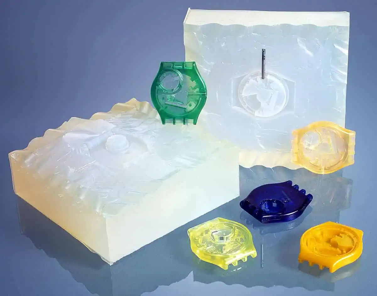
Example: Producing ABS plastic parts with a 35% non-uniform wall thickness leads to different cooling rates, causing warping and quality issues. Redesign and unforeseen new mold costs could have been avoided by following design for injection molding rules.
Striving Towards Better Solutions
We now know what happens when DfM principles are not considered. But what are the upsides of DfM, or simply, why should you bother with adding more complexity to your design process?
Simplicity
The first objective of design for manufacturing is simplifying geometry. This means using the simplest design that maintains the desired functionality, while increasing the part’s machinability, moldability, printability, or whatever the chosen fabrication method.
DfM often involves minimizing the number of parts or components in a product by combining functions when possible, leading to simpler manufacturing and assembly processes and lower production costs.
Ultimately, a longer and more complex design process results in products that are simple to manufacture.
Easy Assembly
Strictly speaking, assembly falls under Design for Assembly or DfMA. However, it is included here as it is an important stage of the overall manufacturing process.
Assembly optimization means minimizing complex or manual assembly steps. Engineers achieve this by designing parts that fit together easily with no special tools. Additionally, applying poka-yoke principles helps avoid mistakes by allowing a single way of assembling.
Example: Snap-fit joints for plastic products allow parts to be fitted together with no tools, reducing the time and cost of the assembly process.
Standardization
Using standardized components, materials, and processes significantly reduces production costs and manufacturing time. It also simplifies maintenance for the end-user (see our article on Design for Maintenance). Conversely, manufacturing custom parts is inherently expensive and time-consuming.
Standardization also ensures elevated consistency in product quality.
- Standard Dimensions: Designing for standard radii and thicknesses such as using common sheet metal gauges, simplifies the manufacturing process.
- Supply Chain: Using materials that are readily available in your vicinity makes finding suppliers easier, reducing both lead time and logistics costs.
Realistic Tolerances
In DfM, tolerances are optimized to ensure a correct fit between components. However, engineers must be wary of over-tolerancing, as tight tolerances have a massive impact on overall manufacturing costs.
The basis for getting this right involves two steps:
- Understanding the accuracy necessary to ensure function and longevity.
- Knowing the achievable accuracy levels of different manufacturing processes.
While CNC machining can achieve extremely high precision, standard engineering fits guidelines always direct the engineer to the loosest viable option that still ensures functionality.
Example: If you are sourcing sheet metal fabrication parts, tolerance requirements play a huge role in process selection. Flame, Plasma, Laser, & Waterjet: All can cut ferrous sheets.
The accuracy and cost will vary significantly between them. Specifying a tighter tolerance than necessary might force you into a more expensive process like laser cutting when plasma would have sufficed.
Constant Progress (Iterative Design)
DfM is not a one-time checkbox; it is an iterative process. Designs should be regularly reviewed by cross-functional teams, including manufacturing engineers, to identify potential issues in quality or production flow.
New information often comes to light after initial test runs or the start of production. It is essential to accommodate these new learnings to optimize the design for better quality and speed.
- Continuous Improvement: Instead of shipping “good enough” products, DfM always encourages looking to improve solutions.
- Business Impact: This aligns with the philosophy of “making your own existing products obsolete through innovation” rather than leaving that opportunity to competitors.


Design for Manufacturing Principles
Design for Manufacturing focuses on the critical elements that directly dictate the success of the production stage: finding the right process, defining the product geometry, and making the correct material selection.
Let’s dig deeper into each of these steps.
Manufacturing Process Choice
After the initial design phase, the engineering team must select the most suitable manufacturing process. This choice is rarely black and white; it is a strategic balancing act between quality needs, production volume, and cost constraints, often visualized by the project management triangle.
- Tooling Strategy: Designers must consider tooling (molds, dies, fixtures) early on. Tooling is often the single biggest upfront cost driver, so selecting a process that aligns with your volume is essential.
Process Selection Example: CNC vs. Sheet Metal
- CNC: Selected when high precision and complex 3D geometry are non-negotiable. CNC machining offers flexibility but scales poorly in cost for high volumes.
- Sheet Metal: Often the better choice for enclosures and brackets. Just knowing the design guidelines for sheet metal bending can unlock a simpler, cost-effective solution that is easily scalable from laser cutting to automated punching.
Design
The design stage is split into two distinct phases: Initial Design and Detailed Design.
- Initial Design Phase: This establishes the primary geometry and functionality. It must be compatible with the intended manufacturing process from the start; otherwise, the detailed design phase will be wasted on unmanufacturable features.
- Detailed Design Phase: Once the process is locked in (e.g., CNC Machining), the design is refined using specific DfM principles. The final design must respect the limitations of the method while maximizing its unique capabilities.
Practical Application: CNC DfM Checks If the team settles on CNC machining, the detailed design phase would focus on CNC-specific design principles.
- Internal Radii: Ensuring corners match standard end mill radii.
- Wall Thickness: Avoiding thin walls that cause chatter.
- Standardization: Aligning hole sizes with standard drill bits to avoid custom tooling.
- Precision: Avoiding tight tolerances on non-critical features to reduce machine time.
Material Selection
Material selection is a primary driver for manufacturing cost, quality, achievable tolerances, and production cycle times. Engineers must evaluate materials not just for end-use performance, but for processability—how the material behaves under machining, molding, or printing stresses.
Cost analysis must extend beyond raw material price to include availability, machine wear, and waste disposal requirements.
| Property Category | Key Consideration | Manufacturing Impact |
| Mechanical | Strength, Hardness, Impact Resistance | Harder materials increase tool wear and machining time; high impact resistance is crucial for durable casings. |
| Thermal | Conductivity, Expansion,Heat Resistance | High thermal expansion leads to warping in injection molding; conductivity dictates cooling cycle times. |
| Processability | Viscosity, Machinability, Weldability | Determines cycle speed (e.g., flow rate in molding) and defect rates during production. |
| Electrical | Conductivity, Dielectric Constant | Essential for parts requiring EDM (Electrical Discharge Machining) or electrical insulation. |
| Physical | Density, Optical Clarity | Density affects shipping weight and material usage; clarity requires high-polish mold finishes. |
Example: Polycarbonate (PC) Housings Smartphone casings are often made of Polycarbonate due to a specific balance of properties:
- Impact Resistance: High durability protects internal electronics.
- Moldability: Good flow properties allow for complex geometries and thin walls.
- Outcome: Faster manufacturing cycles and reduced defect rates compared to less processable plastics.

Integration of DfM in the Design Process
For DfM to be effective, it must be integrated from the onset of the product development cycle. Treating DfM as a final “check” before production often results in costly redesigns. Instead, it should be a continuous loop of testing and refinement.
The integrated DfM workflow typically follows two distinct stages:
1. Preliminary DfM (Concept Phase)
This stage occurs during concept development and material selection. The goal is to establish a viable foundation before detailed CAD work begins.
- Define Requirements: Clearly define functional requirements to narrow down suitable materials.
- Process Selection: Select possible manufacturing methods early (e.g., Die Casting vs. Machining).
- Limit Check: Develop initial concepts while explicitly considering the constraints of the chosen process.
- Review: Conduct initial reviews with manufacturing engineers to flag major feasibility issues.
2. Detailed DfM (Validation Phase)
Once the concept is frozen, detailed DfM focuses on optimizing the specific geometry and documentation.
- Geometry Optimization: Adjust wall thicknesses, radii, and features based on testing results.
- Tolerance Analysis: Validate that tolerances are achievable and necessary.
- Prototype Validation: Use prototypes to validate assumptions and catch unforeseen physical issues (e.g., vibration, heat dissipation).
- Documentation: Finalize technical drawings and specifications.
Optimizing an Aluminum Pump Scenario
A manufacturer is developing a small aluminum pump. The initial design outlines the basic flow path.
Phase 1: Preliminary DfM The design team engages manufacturing engineers and procurement specialists early. They identify potential supply chain risks and general machining constraints.
Phase 2: Prototyping & Discovery The first prototype reveals two critical issues:
- Deep Cavities: Required expensive, non-standard tooling.
- Vibration: Caused by thin walls flexing under load.
Phase 3: Detailed DfM Correction The team reduces the cavity depth to match standard tooling reach and increases wall thickness for rigidity.
The final prototype confirms stable performance with significantly lower tooling costs.
Checklist: The DfM Audit
Throughout the lifecycle, the engineering team should validate the design against these key questions.
- Can the product be manufactured using standard components and processes?
- Are the tolerances too tight? Is a standard tolerance block sufficient?
- Are there parts that could be combined or eliminated to reduce assembly time?
- Does the process require custom tooling or setups? If so, is the cost justified?
- Is the assembly stage easy?
- Is the entire manufacturing workflow cost-effective given the volume?


Teams Involved in DfM
Successful DfM is inherently cross-functional. It requires breaking down the silos between the design studio and the shop floor. It is not just the Design Engineer’s job; it is a collaborative effort involving multiple stakeholders.
The DfM Responsibility Matrix
| Role | Key DfM Responsibilities | Critical Interactions |
| Design Engineers | Create the initial geometry and collaborate to ensure efficiency and cost-effectiveness. | Must receive critical dimensions and tolerance data from Maunufacturing Engineers. |
| Manufacturing Engineers | Define processes, tooling, and equipment constraints after concept definition but before finalization. | Provide inputs on cycle times and tooling costs to Design and Cost teams. |
| Procurement | Identify viable suppliers and ensure raw material quality and availability. | Works with Manufacturing to validate if specified materials are sourceable. |
| Quality (QA/QC) | Define quality standards and identify potential defect risks early in the design phase. | Establishes inspection procedures with Design and Manufacturing teams. |
| Cost Estimators | Calculate manufacturing costs based on design plans to determine the financial impact of design decisions. | Validates if the “optimized” design actually reduces total unit cost. |
| Product Managers | Ensure the manufacturable design still meets customer needs and company goals. | Acts as the gatekeeper between technical constraints and market requirements. |
Design for Manufacturing (DfM) Analysis Tools and Techniques
DfM analysis utilizes various techniques and tools, including failure mode and effects analysis (FMEA), finite element analysis (FEA), and DfM analysis and CAM software.
Analytical Methodologies (FMEA and FEA)
- FMEA (Failure Mode and Effects Analysis): A systematic approach used to identify and prioritize potential failures in a design or process. In DfM, FMEA is used to mitigate risks associated with specific manufacturing steps.
- FEA (Finite Element Analysis): Uses mathematical models to predict how a part will behave under physical stresses (vibration, heat, load). This highlights geometry that needs reinforcement before production.
DfM Analysis Software
- CAD Integrated DfM: Tools like DFMPro integrate directly into CAD software, flagging issues like deep holes or tight radii in real-time.
- CAM & Simulation: Engineers use CAM tools to simulate toolpaths and part orientation. This allows for the detection of collisions, unmachinable features, or mold flow issues before cutting steel.
- AI-Powered DfM Checks Online quoting engines (like the Instant Quoting Engine®) act as a rapid DfM tool. By uploading a step file, engineers receive immediate feedback on manufacturability issues such as thin walls or inaccessible features based on the chosen process.
Simulation & Rapid Prototyping
Simulations of the product or manufacturing process using tools, such as CAD and CAM tools, allow engineers to test several aspects of the product/process. That includes toolpaths, part geometry and orientation, material selection, and product assembly, before prototyping to minimize issues.
Simulations are the easiest way to get quick feedback on designs. 3D printing is typically used for rapid prototyping, enabling engineers to reduce testing time and quality problems.
Integration of Sustainable Practices in DfM
Growing awareness among consumers and businesses regarding environmental problems is driving the adoption of sustainable practices that sometimes exceed regulatory requirements.
Material Selection
Sustainability-focused DfM prioritizes renewable, biodegradable, locally sourced, or recycled materials. Engineers select materials that meet performance requirements (mechanical, thermal, etc.) while ensuring their sustainability and low environmental burden.
Disposal
In design for manufacturing, engineers consider waste disposal for environmental protection and to comply with environmental regulations.
Design engineers inspect disposal methods of the products and raw materials early in the design phase, as they directly affect material selection.
Energy Consumption
Sustainability-focused DfM considers the energy consumption of the manufacturing and disposal processes because it affects the footprint of the project and the product cost. Thus, when engineers select processes and materials, they calculate their energy consumption.
Example: Industrial heat exchangers often utilize energy from hot water effluents to preheat boiler feed water. Integrating such recovery loops at the facility design level significantly reduces operational energy costs.
Life Cycle Analysis
Life cycle analysis (LCA) is the standard tool for quantifying environmental impact.
By integrating LCA into the DfM stage, engineers can simulate the carbon footprint of different design iteration such as changing geometry to reduce material mass or switching processes to lower emissions before committing to production.
The DfM Timeline: What Drives Schedule?
There is no fixed duration for a DfM process; it scales with the project’s scope. However, understanding the variables that expand the timeline allows project managers to plan realistic buffers.
Lead Time Impact Factors
| Factor | Impact on Timeline | Mitigation Strategy |
| Product Complexity | High. More features mean more tolerance stacks and potential failure modes to analyze. | Modularize the design to simplify analysis. |
| Team Expertise | Medium. Inexperienced teams may require more iteration cycles. | Involve senior manufacturing engineers early. |
| Testing Requirements | High. Physical prototype testing (fatigue, thermal) takes days or weeks. | Use simulation (FEA) to validate early concepts before physical testing. |
| Regulatory Compliance | High. Medical or aerospace certifications add significant documentation time. | Integrate compliance checks into the initial DfM review. |
| Supply Chain | Medium. Sourcing exotic materials can delay prototype builds. | Design around standard, in-stock materials. |
Challenges of Design for Manufacturing
We have outlined the perks of implementing Design for Manufacturing principles in the product development cycle.
While the logic of DfM is undeniable, implementation often fails due to human and organizational factors rather than technical ones.
Communication
Clear communication between different teams enables organizations to avoid project delays. The prerequisite is buy-in from all team members, so they would be willing to put in the effort needed for seamless communication.
Timing
The timing of each team’s integration into DfM should be optimized. Bringing teams too late can lead to redesigns and additional costs. Getting them in too early means unnecessary confusion and a plethora of opinions at a stage that does not need it.
Example: Bringing in the procurement team after prototyping could surface issues with finding the right suppliers. This could mean longer-than-intended lead times, or alternatively, a need for redesigns.
Understanding Process and Equipment
Engineers with a deep understanding of the available equipment/process capabilities and limitations achieve successful DfM. Conducting the design based on a process and then discovering that it has limitations that can prevent optimal manufacturing of the product leads to redesigns and delays.
The Performance vs. Manufacturability Trade-Offs
Manufacturability requires design simplifications, which sometimes lead to diminished performance. Engineers can optimize the production process to balance performance and manufacturability. Moreover, the choice of processes, materials, and design aspects is affected by cost and vice versa.
- Material Trade-off Example:
- Mild Steel: Low cost, excellent weldability, easy to machine. (Best for Manufacturability)
- Stainless Steel: High corrosion resistance, no coating needed, but harder to machine and weld. (Best for Longevity)
- Decision: The engineer must decide if the extra cost of machining stainless is justified by the removal of the painting process required for mild steel.
Benefits of A Successful Design for Manufacturing Process
Implementing Design for Manufacturing takes quite a bit of effort, but the payoff is manifold and mostly comes in the following areas.
Economic Efficiency
- Cost Reduction: DfM identifies costly features (such as non-standard tolerances or complex contours) before tooling is ordered. This optimizes the production process and lowers labor costs per unit.
- Reduced Waste: Enhancing production efficiency directly reduces scrap rates and raw material consumption, increasing the overall sustainability of the process.
Product Integrity
- Improved Quality: By simplifying geometry and prioritizing assembly logic, DfM reduces the risk of manufacturing defects and enhances field reliability.
- Regulatory Compliance: Integrating safety and regulatory standards into the initial design phase mitigates the risk of late-stage product rejections or forced redesigns.
Strategic Advantage
- Faster Time to Market: Efficient DfM processes minimize Engineering Change Orders (ECOs) during production. While the design phase may take longer, the total time from concept to shipping is significantly reduced.
- Innovation & Competitiveness: DfM encourages cross-functional collaboration. This diversity of perspective (Design + Manufacturing + Supply Chain) often leads to innovative solutions that satisfy market needs more efficiently than competitors.
Pro Tip: The “Rule of 10” In product development, the cost to fix a defect increases by roughly 10x at each stage of the process. A geometry error that costs $100 to fix in CAD might cost $1,000 to fix during prototyping and $10,000 to fix once tooling is cut. DfM keeps you in the “$100 zone.”
Mastering the Manufacturing Mindset
Adopting Design for Manufacturing (DfM) principles is the most effective way to reduce production costs and secure timelines. It transforms manufacturing from a reactive “supply chain” step into a proactive design constraint.
Key Takeaways:
- The feedback loop between design and manufacturing engineers drives the process and minimizes trial runs.
- Success relies on design simplicity, standardized materials, and the avoidance of over-tolerancing.
- Leveraging simulations and rapid prototyping (3D printing) accelerates validation.
Ready to validate your design? Upload your CAD file to the Xometry to receive automated DfM feedback on your parts in seconds.

Comment(0)