 Europe
  Türkiye


Within this system, straightness belongs to the Form Control family, a group that also includes flatness, cylindricity, and circularity. Unlike location or orientation controls, form controls do not require a datum reference; they apply directly to the shape of the feature itself.
In this guide, we will explore how to apply, interpret, and measure Straightness in real-world manufacturing.
| Functional Goal | Correct Callout | Inspection Method |
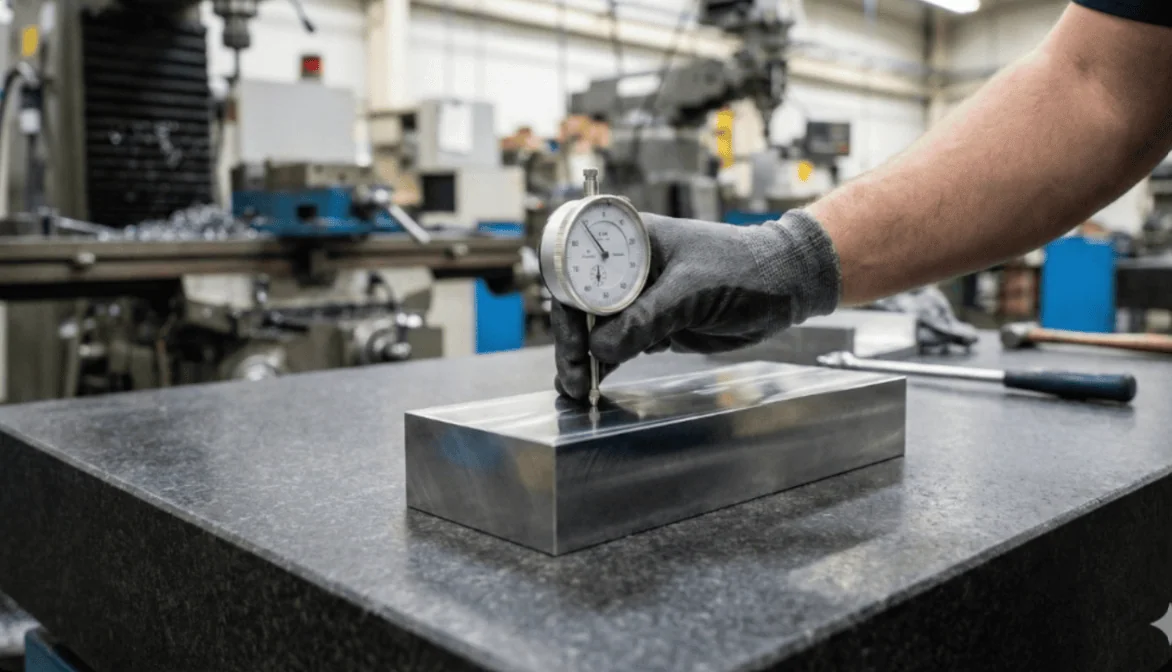
| Sealing / Contact | Surface Straightness (Arrow on surface) | Dial indicator scan of the surface line. |
| Assembly / Fit | Axis Straightness (Arrow on dimension) | Functional Gauge (Ring/Plug) or CMM calculation of the axis. |
What is Straightness in GD&T?
Straightness is a form tolerance used to control how straight a specific feature is. While the concept sounds simple, its application in GD&T is split into two distinct categories depending on what you are trying to control: Surface Straightness or Axis Straightness.


1. Surface Straightness (2D Control)
When applied to a surface, the Straightness callout controls the linearity of individual line elements on that surface. It does not control the entire surface at once (that would be Flatness).
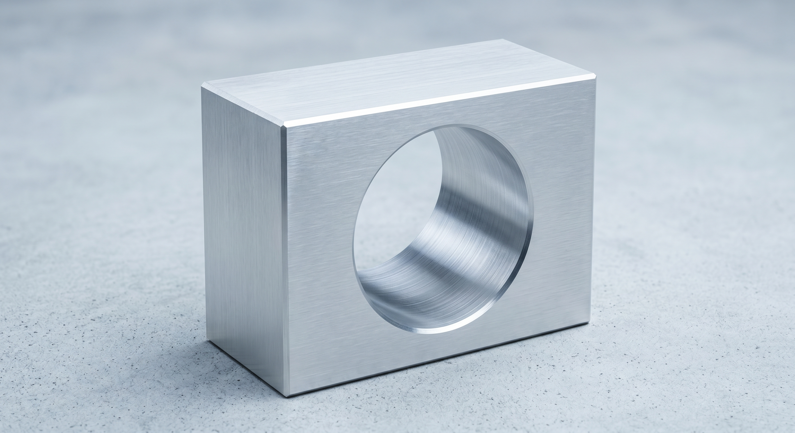
Example: Surface straightness is typically used on parts where uniform contact is critical.
- Consider a hydraulic block with a mating surface. If the surface bows too much, the gasket won’t seal properly.
- Excessive variation leads to poor sealing, leakage, or accelerated wear.
- By applying surface straightness, you ensure that every cross-section of that sealing face remains flat enough to function, preventing structural failure.

2. Axis Straightness (3D Control)
When applied to a “Feature of Size” such as the diameter of a shaft, pin, or hole, the callout controls the straightness of the feature’s central axis, not the surface itself.
Example: Axis straightness is critical for assembly fits.
- You have a long pin that must pass through a hole. Even if the pin’s diameter is within tolerance, if the pin is bent, it will jam during assembly.
- Axis straightness limits how much the pin can bend, ensuring the derived median line stays straight enough to mate with the corresponding hole.
Straightness Tolerance Zone
The tolerance zones for surface straightness and axis straightness differ significantly from one another. Understanding this difference is critical, as it changes how the part is inspected.
Surface Straightness Tolerance Zone
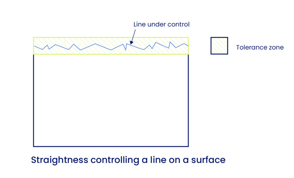
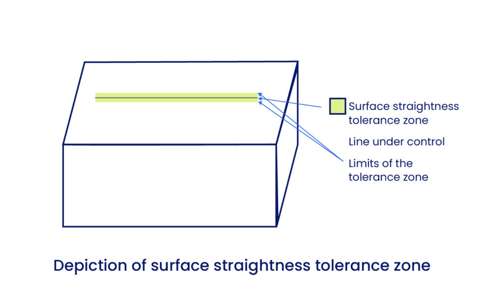
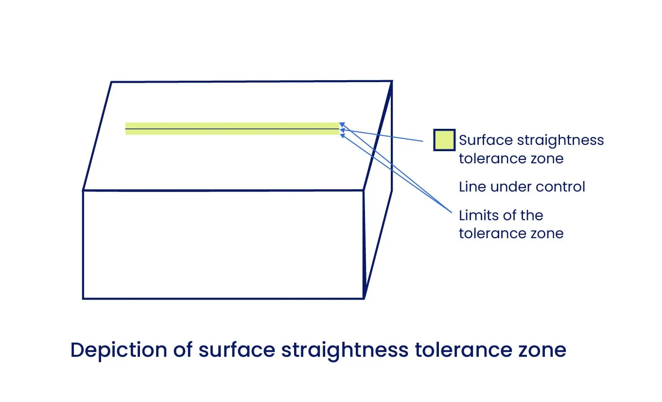
When controlling Surface Straightness, we are effectively controlling a specific cross-section of the surface.
- The Geometry: The tolerance zone consists of two parallel lines positioned on either side of the cross-section, creating a 2D plane.
- The Rule: This is the default tolerance zone in GD&T, often referred to as a Total Wide Zone. [Check the image below]
To pass the straightness check, all points on the actual surface line must lie within this 2D plane.
In reality, no surface can be perfectly straight. This callout allows designers to clearly define the permissible deviation that still allows the part to perform its function. For an optimal manufacturing experience, this tolerance should be kept as loose as practical.
Axis Straightness Tolerance Zone
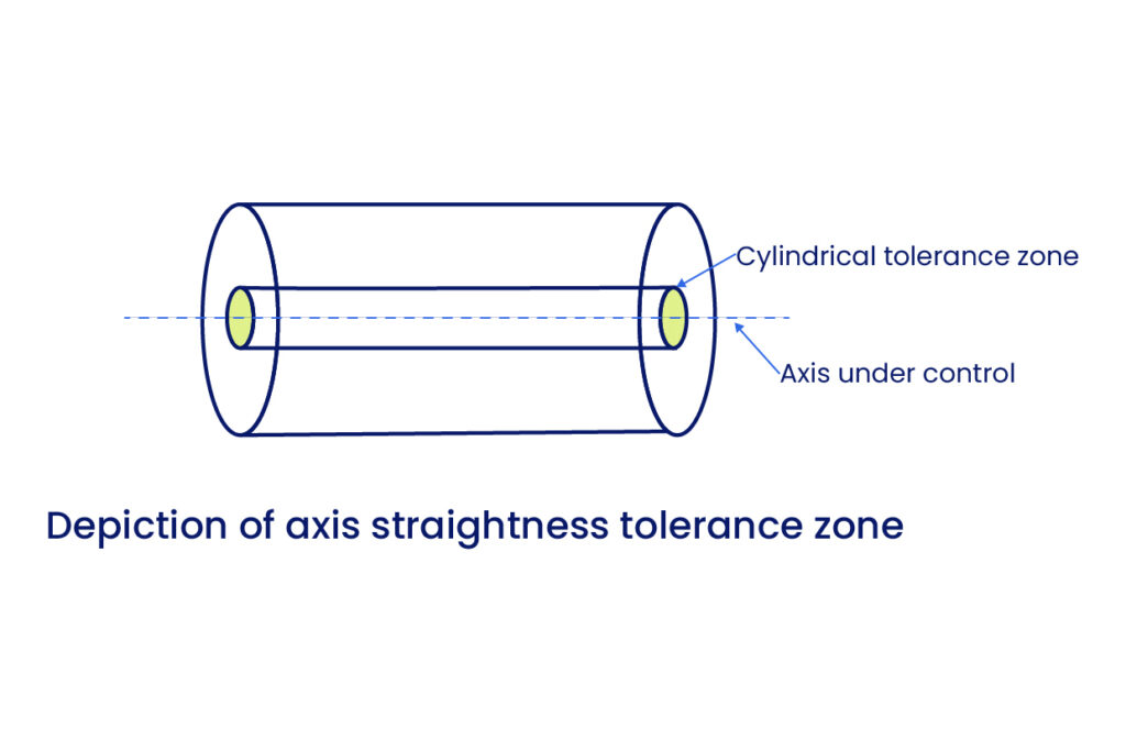
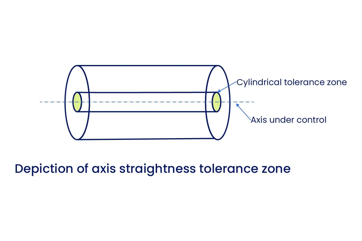
In contrast to the 2D surface zone, the Axis Straightness tolerance zone forms a cylindrical envelope around the ideal axis of the part.
- The Geometry: The tolerance applies in all directions around the central axis.
- The Rule: All points constituting the actual feature’s axis must lie within this cylindrical zone for the part to be acceptable.
This actual axis is technically known as the Derived Median Line. [Check the image below]
It is calculated by determining the center point of all circular cross-sections along the length of the feature and connecting them. When measuring the straightness of a Feature of Size, you are verifying that this derived median line remains within the cylindrical tolerance zone defined by the ideal axis.
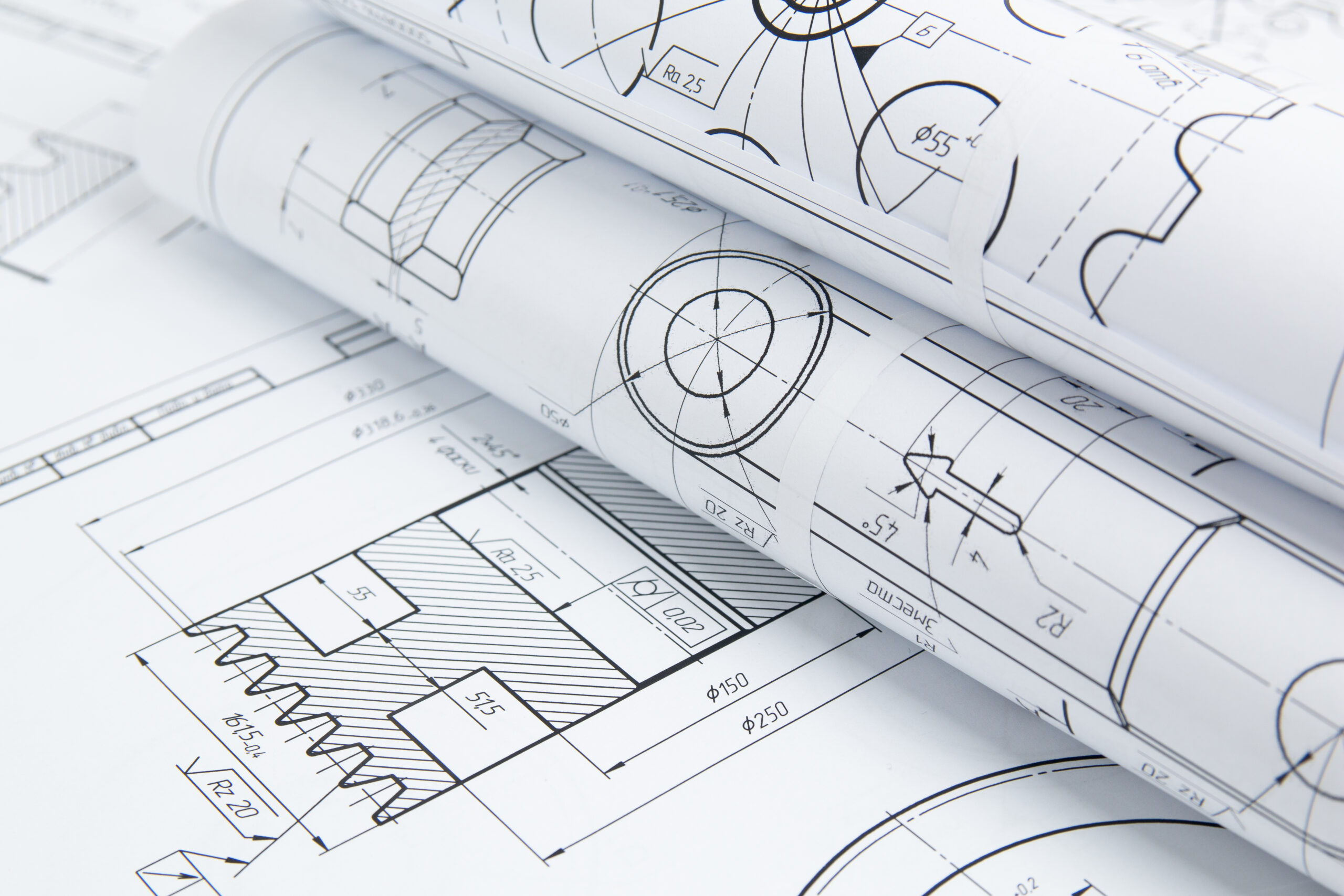
How to Show Straightness in a Drawing?
The straightness callout is defined within a Feature Control Frame. This frame contains the necessary information to define the tolerance scope. The critical distinction between controlling a surface and controlling an axis is determined entirely by the placement of the leader arrow.
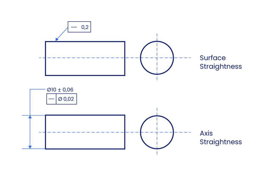
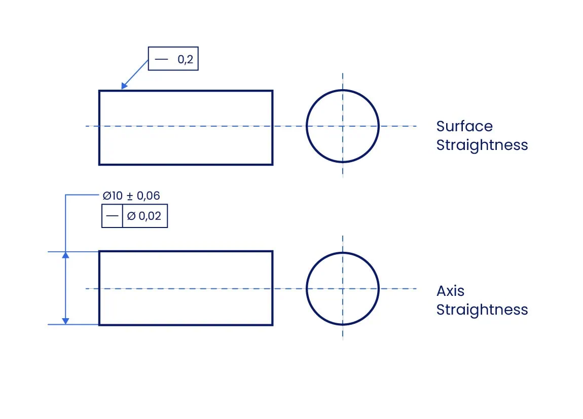
1. Indicating Surface Straightness
To control the surface form, the leader arrow points directly to the surface or an extension line of the surface.
- Symbol: The straightness symbol (—) is in the first compartment.
- Tolerance Compartment: Contains only the tolerance value.
- Zone: There is no symbol for the zone type, as it defaults to a Total Wide Zone (two parallel lines).
- Modifiers: No material modifiers or datums are used.
2. Indicating Axis Straightness
To control the feature’s axis, the leader arrow points to the size dimension (e.g., the diameter value of a shaft).
- Tolerance Compartment: The tolerance value is preceded by the diameter symbol (Ø). This explicitly defines the tolerance zone as a cylinder.
- Modifiers: Unlike surface straightness, axis straightness may use Material Modifiers (such as Maximum Material Condition) to enable bonus tolerances.
Straightness vs. Other Tolerances
Surface straightness may seem a bit similar to flatness, and the same applies to axis straightness when comparing it to cylindricity. So let’s sort out the differences.
Straightness vs. Flatness
Straightness is effectively the one-dimensional equivalent of Flatness.
- Flatness: Controls an entire surface. It requires the surface to lie between two parallel planes.
- Straightness: Controls a single line element on a surface. It requires the line to lie between two parallel lines on a plane.
- Neither control requires a datum reference.
Straightness vs. Cylindricity
While both apply to cylindrical parts, Cylindricity is a stricter control.
- Straightness (Axis): Ensures the Derived Median Line lies within a cylindrical zone. The surface itself may be oval or irregular, provided the axis is straight.
- Cylindricity: Controls both the straightness of the axis and the roundness of each cross-section simultaneously. It forces the feature to be as close to a perfect tube as possible.
Measuring Straightness
Verifying straightness requires specific metrology tools chosen based on the tolerance tightness and feature type.
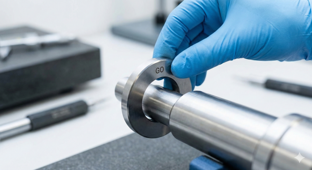

1. Function Gauge (Go/No-Go)
A function gauge allows for quick pass/fail inspection of Axis Straightness.
- Tool Type: A Ring Gauge is used for external features (shafts), while a Cylindrical Plug Gauge is used for internal features (holes).
- Condition: Maximum Material Condition (MMC) for an external feature (shaft/pin) is its maximum allowable diameter (max size + tolerance); for an internal feature (hole), it is the minimum allowable diameter.
- Limitation: Each distinct feature requires a custom gauge. It does not provide numerical data, only a binary result.
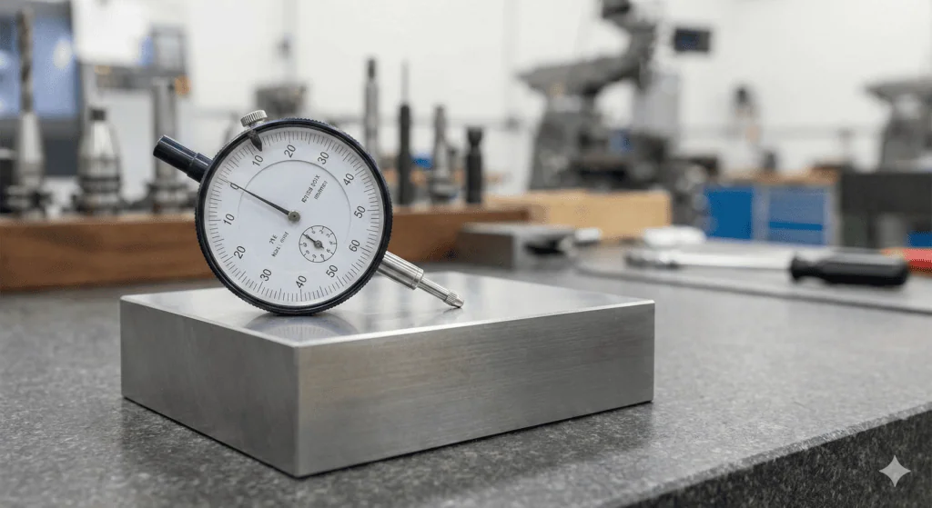
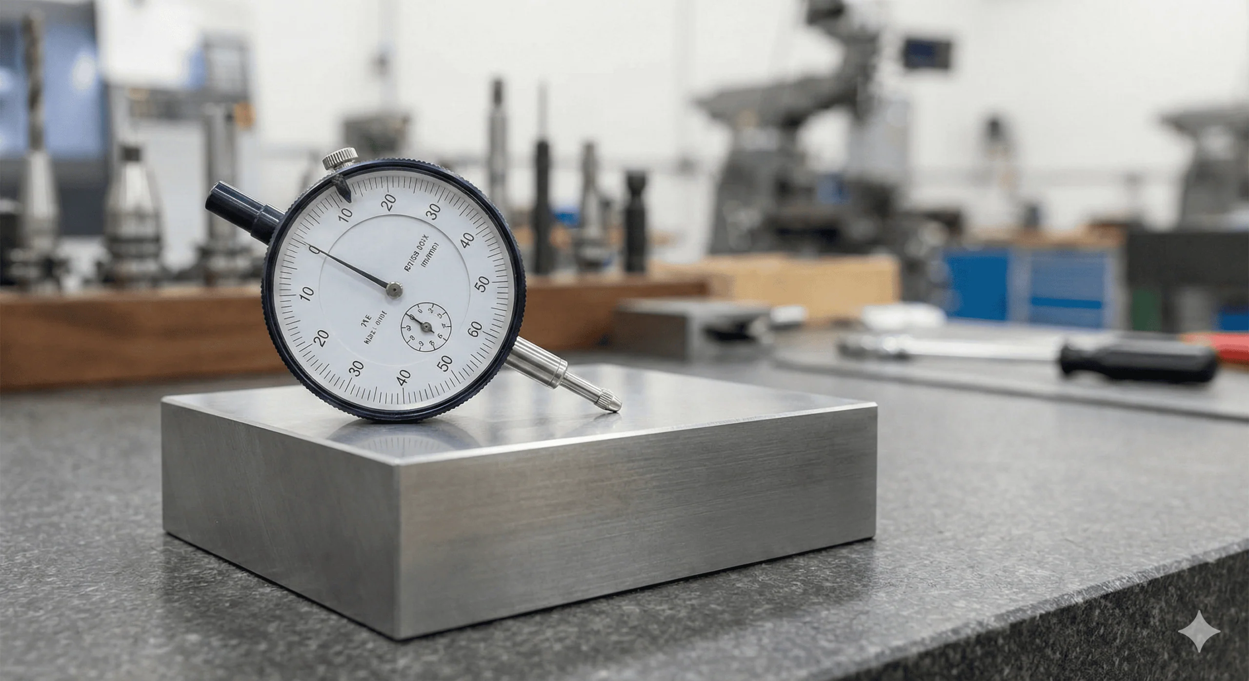
2. Height Gauge with Dial Indicator
This setup measures the deviation of cross-sections to verify the axis or surface. We can also use a height gauge combined with a dial indicator to check the straightness of an article.
- Setup: The part is fixed on a V-block or rotating fixture to ensure perfect alignment.
- Method: A dial indicator is zeroed on the surface. The part is rotated or scanned along the axial direction.
- Result: The indicator measures the variance in height. If the variation stays within the tolerance band, the part passes.
3. Coordinate Measuring Machine (CMM)
CMMs provide highly accurate digital profiles but require longer cycle times than dial gauges.
- Method: The part is secured on the CMM bed. A probe traces the surface radially at selected cross-sections to map the geometry.
- Probe Types:
- Ball-Stylus: Standard probe, capable of picking up general form.
- Contour Tracer: Generally outperforms ball-stylus probes for straightness as they can detect finer surface details and peaks/valleys more accurately.
4. Autocollimator
Autocollimators offer high-accuracy measurement using optical principles (mirrors and light beams). They typically come with a laser alignment aid and a computer terminal.
- Method: A computer program converts reflections from the surface into a 2D map.
- Environmental Sensitivity: The device is highly sensitive to external factors. Air turbulence from open doors, fans, or temperature gradients can distort readings. Even a gentle tap on the back of the device or fixture can alter the result, so a stable environment and secure fixturing is mandatory.
Material Modifiers and Bonus Tolerance
Axis straightness is often applied with Material Modifiers to ensure proper assembly while offering manufacturing flexibility.
The Maximum Material Condition (MMC) Effect
When the straightness callout includes the MMC modifier (M), the specified tolerance applies only when the part is at its Maximum Material Condition (e.g., the largest allowable shaft diameter).
Calculating Bonus Tolerance
As the manufactured part size departs from MMC (e.g., the shaft gets smaller), the manufacturer gains Bonus Tolerance.
- Formula: Total Straightness Tolerance = Specified Tolerance + (MMC Limit – Actual Size)
- At MMC: The bonus is zero. The part must meet the strict straightness value in the Feature Control Frame.
- At LMC (Least Material Condition): The bonus is at its maximum.
Why use it?
This mechanism ensures that the assembly fits in the “worst-case” scenario (largest pin, worst straightness). If the pin is smaller than the maximum size, it can be “more bent” and still fit through the hole. This reduces scrap rates and production costs without compromising function.
Glossary of Key Terms
| Term | Definition | Context |
| Total Wide Zone | The default 2D tolerance zone consisting of two parallel lines. | Used strictly for Surface Straightness. No diameter symbol (Ø) is present. |
| Derived Median Line | An imaginary line calculated by connecting the center points of all cross-sections along a feature. | Used strictly for Axis Straightness. The straightness tolerance controls the waviness of this specific line. |
| Bonus Tolerance | Additional tolerance available when a feature of size departs from its Maximum Material Condition (MMC). | Only available for Axis Straightness when the (M) modifier is applied. |
| Virtual Condition | The collective boundary generated by the combined effect of the feature’s size at MMC and the geometric tolerance. | Critical for designing mating parts (e.g., ensuring a pin fits into a hole). |
Mastering Form Controls
Straightness is the foundation of GD&T Form Controls, but it is rarely used in isolation. To create fully manufacturable parts, engineers must understand how it interacts with other tolerances:
Vs. Flatness: If you need to control the entire sealing face, not just a line, use Flatness.
Vs. Cylindricity: If you need to control the roundness of a shaft in addition to its straightness, use Cylindricity.
For deeper insights into these related controls, explore our comprehensive guide on Geometric Dimensioning and Tolerancing in Xometry Pro technical library.


Comment(0)