 Europe
  Türkiye


Types of Milling Cutters in CNC Machining: A Complete Guide
The cutter library a CNC shop carries is a direct constraint on what that shop can produce. A pocket corner cannot be sharper than the cutter that formed it. A slot cannot be narrower than the smallest tool that reaches its floor. A woodruff keyway requires a woodruff cutter: no geometry substitutes. Every design decision that ignores these physical limits creates avoidable tooling problems, extended lead times, and rework costs that trace directly back to the drawing board.
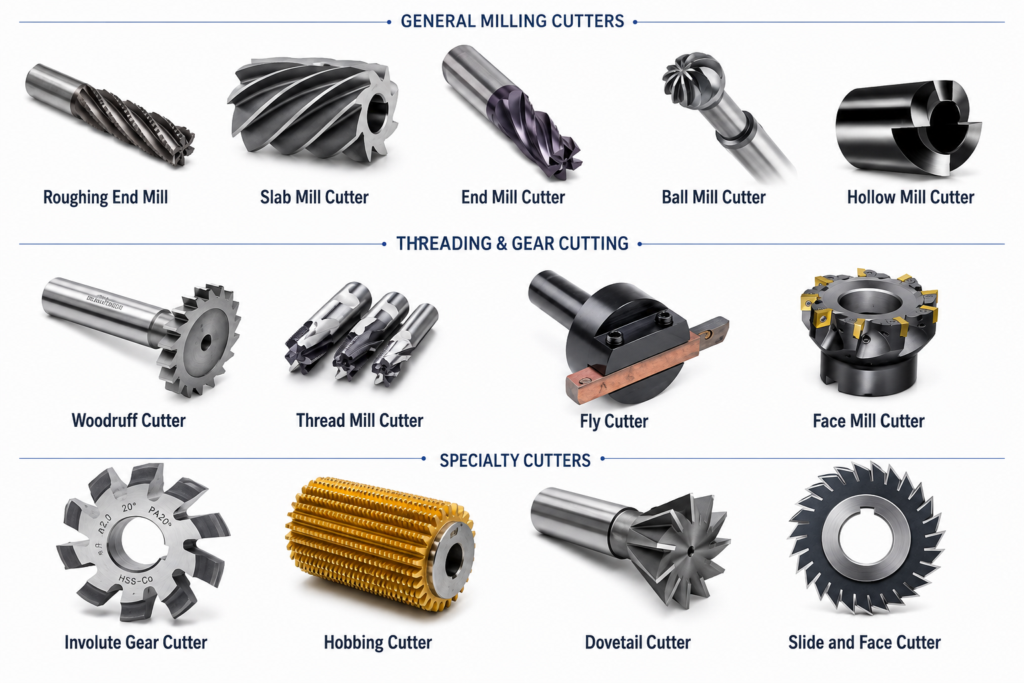
Milling cutters are rotary tools that remove material by engaging a solid workpiece on the end face, the periphery, or both simultaneously. The four main families are end mills, face mills, form and profile mills, and peripheral mills. The first two families cover the vast majority of modern CNC milling process. Understanding each family’s geometry, substrate, and coating requirements is what separates a drawing that machines cleanly from one that needs redesign after the first quote.
Milling Cutter Geometry: Parameters That Govern Performance
All cutter performance traces back to a small set of geometric parameters. These parameters are what machinists reference when they push back on a design, and they are what you need to understand to read a tool catalog accurately.
Flutes
Flutes are the helical channels ground along the cutter body. The cutting edges ride the leading face of each flute; chips evacuate through the channel behind it. Flute count controls chip clearance, core strength, and surface finish simultaneously, and these three outputs compete directly with each other.
| Flute Count | Chip Clearance | Core Strength | Surface Finish | Primary Application |
| 2 | Maximum | Lowest | Coarse | Aluminum, soft plastics, slot cutting |
| 3 | High | Moderate | Moderate | General non-ferrous, light steel roughing |
| 4 | Moderate | High | Good | Steel and stainless profiling, pocketing |
| 5+ | Low | Highest | Best | Hardened steel finishing, high-feed passes |

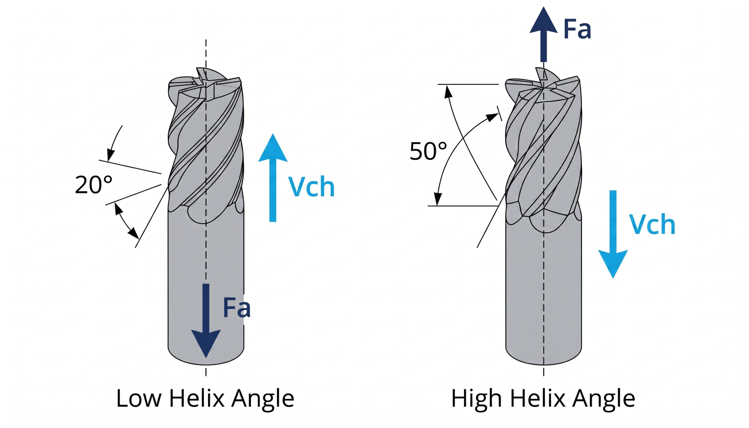
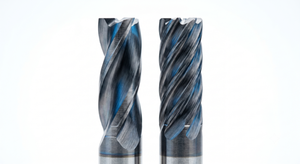
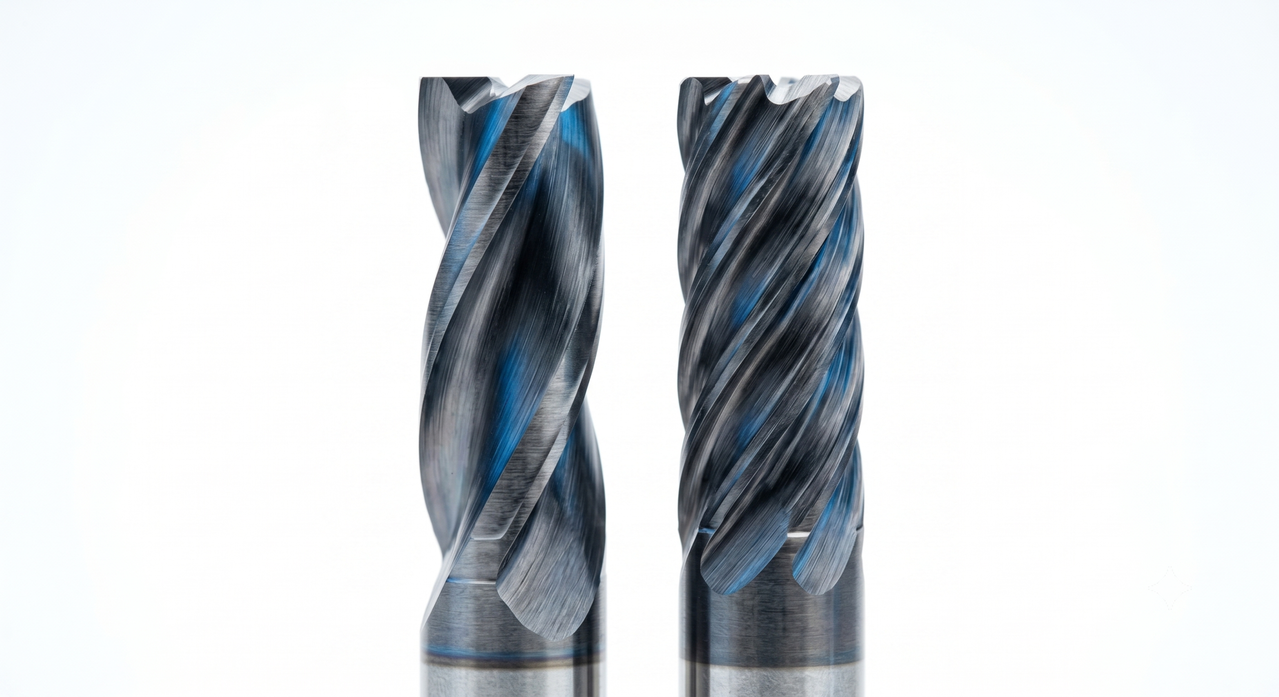
Helix Angle
The helix angle is the spiral angle measured between the flute centerline and the cutter’s longitudinal axis. It typically ranges from 15° to 60°. A low helix angle (below 40°) delivers higher tooth strength, larger chip gullet volume, and lower cutting forces in the axial direction, at the cost of a coarser surface finish and reduced feed rates.
A high helix angle (above 40°) induces lower radial cutting forces and produces a better surface finish, but reduces tool cross-section and increases the risk of tooth failure under heavy loads. Material hardness is the primary driver: soft non-ferrous materials such as aluminum run at a 45° helix or higher; cast iron runs at 20° or below.
Rake Angle
The rake angle controls how aggressively the cutting edge engages the workpiece. A positive rake angle reduces the cutting force required, speeds up chip evacuation, and lowers heat generation. It is the correct choice for softer workpiece materials. A neutral or negative rake angle increases edge strength by thickening the wedge geometry, which is required for hard materials, interrupted cuts, and abrasive workpieces where a positive rake edge would chip rapidly.
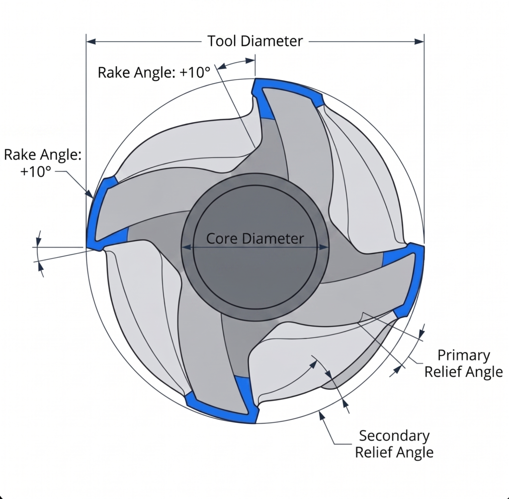
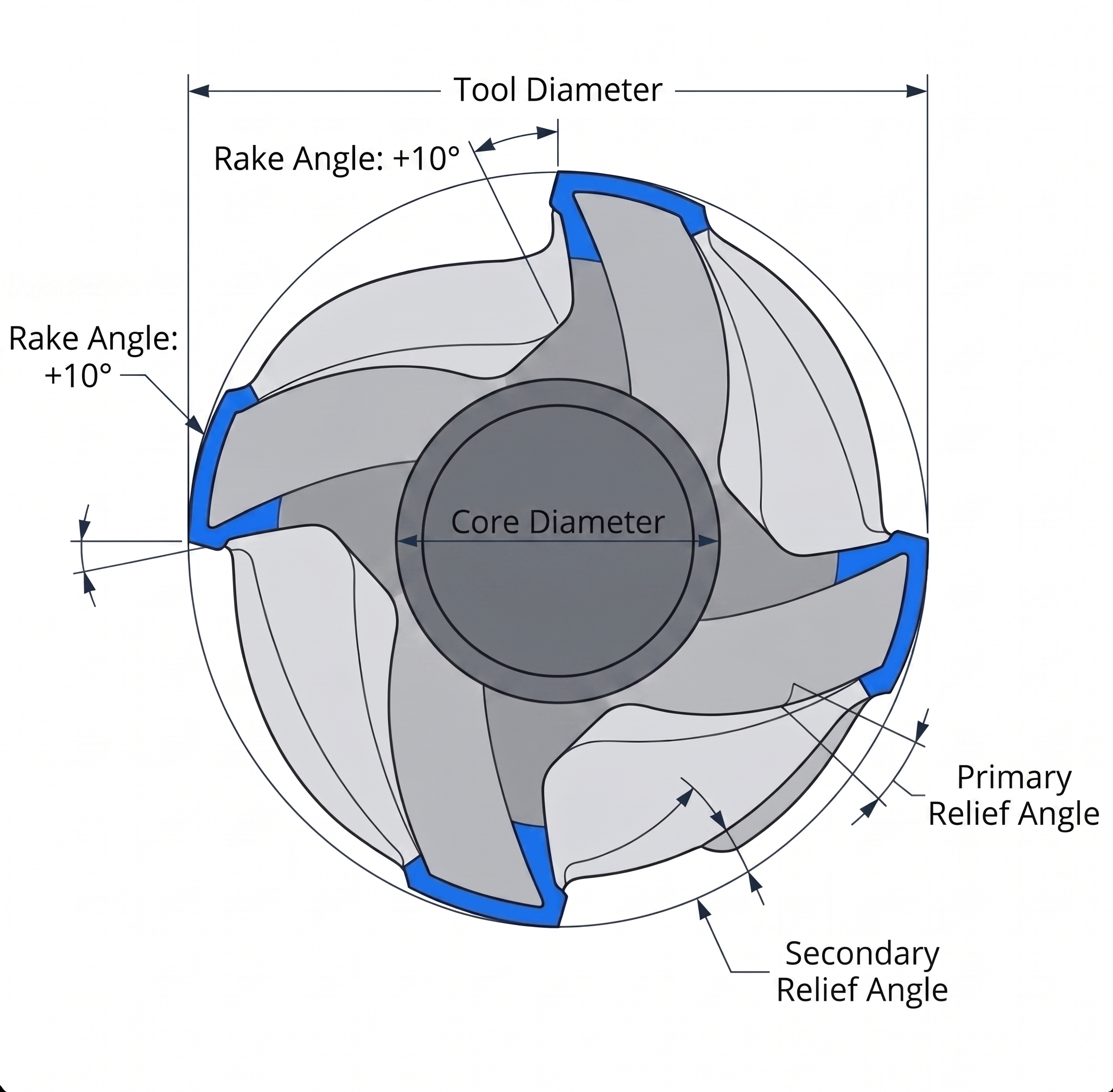
Corner Geometry
Corner geometry determines the existence and size of the fillet radius at an internal pocket corner. Sharp (square) corners concentrate stress at the cutting edge and leave a true 90° internal corner, which creates a stress concentration in the workpiece as well. A corner radius distributes that stress along an arc, extends tool life, and adds a fillet to the workpiece corner.
Designing internal pocket corners with a radius equal to or greater than the standard cutter radius eliminates the need for specialty tooling and reduces machining cycle time. For a full treatment of the cost and manufacturing impact of fillet and chamfer decisions, check this article about fillets and chamfers in CNC machined parts.
Length-to-Diameter (L:D) Ratio
The L:D ratio governs tool rigidity, deflection under cutting load, and the risk of tool breakage. It is the primary geometric constraint for deep pocket and narrow slot features.
| L:D Ratio | Rigidity | Design Implication |
| Up to 4:1 | High | Ideal for aggressive cuts, high accuracy |
| 5:1 to 8:1 | Moderate | Reduce feed and depth of cut, monitor side forces |
| Above 8:1 | Low | High breakage risk, limit to finishing passes only |
Deep, narrow pockets in tough materials like hardened steel, Inconel, and titanium frequently cause tool failure due to length-to-diameter (L:D) constraints. If a pocket’s depth exceeds four times the cutter diameter, the added cost and cycle time must be justified. Implementing more relaxed positional tolerances on these deep features can often mitigate the need for fragile, long-reach tooling.
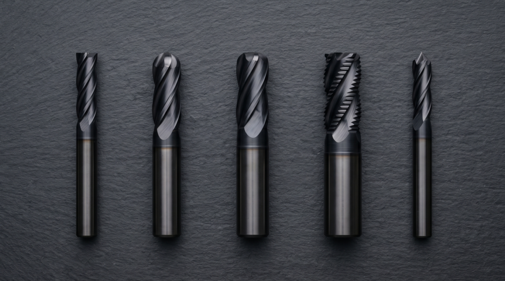
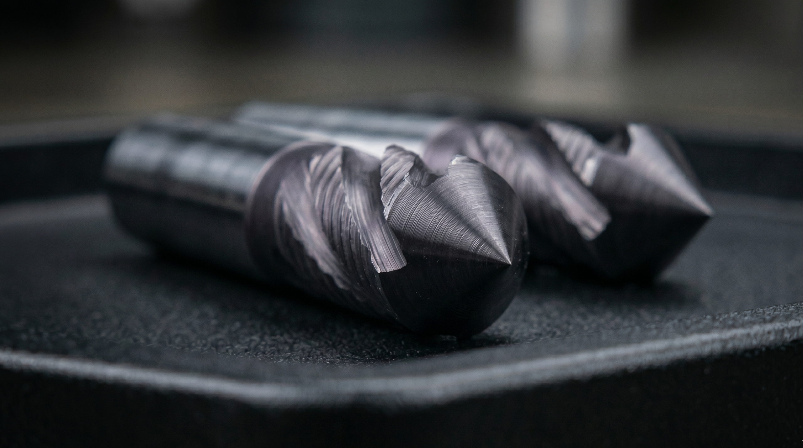
End Mills
End mills cut on both the end face and the peripheral flutes simultaneously, which makes them the most versatile family in CNC milling. A single end mill can plunge, slot, profile, pocket, and step-cut without a tool change, which is why they dominate the cutter lists for vertical machining centers.

Square End Mills
The square end mill is the most common cutting tool on a CNC vertical machining center. Its flat bottom and peripheral cutting edges allow it to plunge axially and traverse radially in a single tool. Typical applications include 2D and 3D pocketing, slotting, profiling, and shoulder milling. Wear concentrates at the corner intersection of the end face and periphery. As the corner rounds from wear, the internal corner radius left in the workpiece grows, even if the engineering drawing specifies a sharp corner. This is the most common source of unintended internal radii in machined parts.
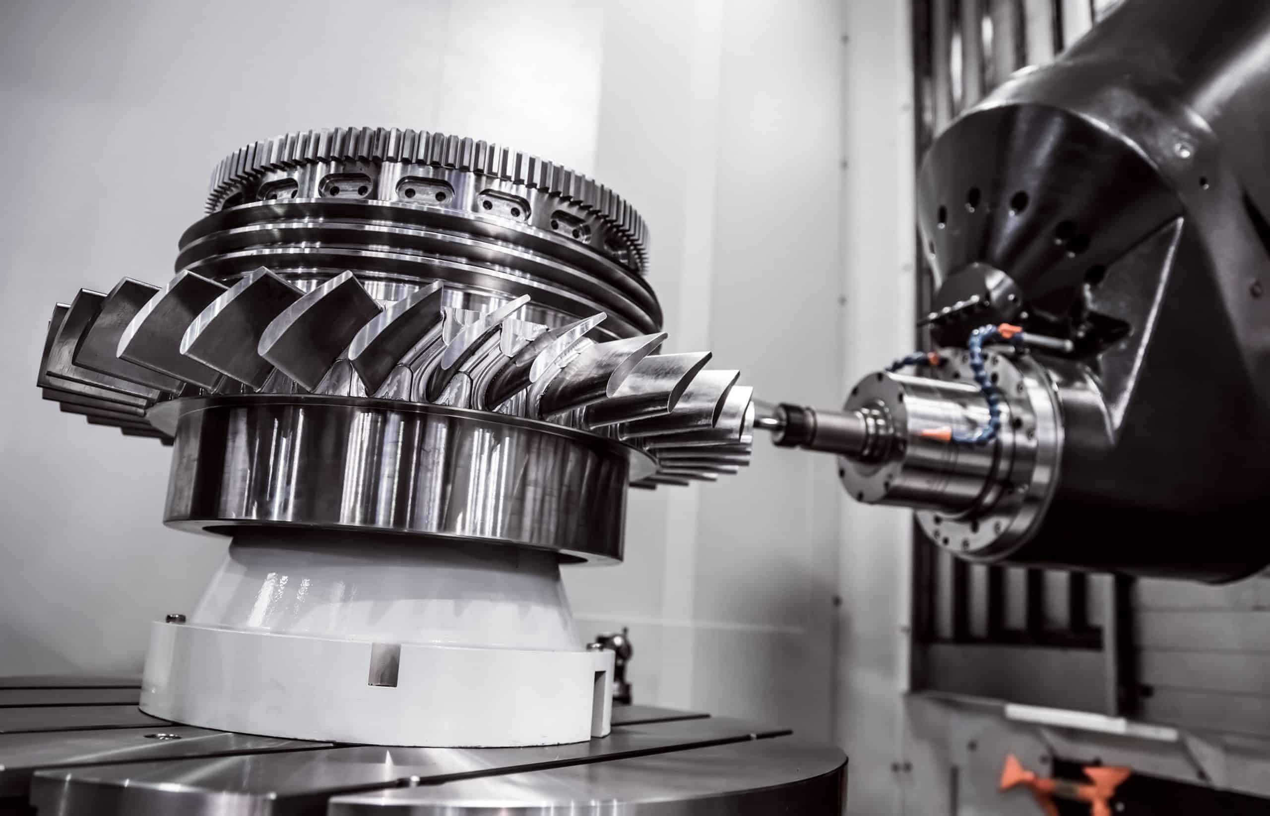
Ball Nose End Mills
The ball nose end mill replaces the flat end face with a hemispherical cutting tip. This geometry traces curved surfaces, which makes it the standard tool for 3D contouring, freeform surface machining, and finish passes on complex mold and die geometries.
The hemispherical tip leaves a scalloped surface profile between adjacent toolpaths. Scallop height is calculated as follows:
h = r − √(r² − (s/2)²)
Where:
- h = scallop height (mm)
- r = ball radius (mm)
- s = stepover distance between adjacent toolpaths (mm)
| Ball Radius r (mm) | Stepover s (mm) | Scallop Height h (mm) | Resulting Ra (approximate) |
| 3 | 0.5 | 0.010 | ~0.4 µm |
| 3 | 1.0 | 0.042 | ~1.6 µm |
| 6 | 1.0 | 0.021 | ~0.8 µm |
| 6 | 2.0 | 0.084 | ~3.2 µm |
Reducing stepover by half reduces scallop height by approximately four times, but doubles the number of passes and machining time proportionally.
Bull Nose End Mills
Bull nose end mills feature a flat cutting face with corner radii, bridging the gap between square and ball nose geometries. They machine flat floors with defined corner radii, distributing cutting stress to extend tool life compared to square end mills. They are ideal for flat pockets requiring specific corner radii, eliminating the need for a secondary corner pass.
Chamfer Mills
Chamfer mills are conical cutters with a defined included angle. A 90° included-angle chamfer mill, the most common configuration, produces 45° edge breaks on the workpiece. It covers chamfering, deburring, and countersinking in a single tool across a wide range of part sizes, since the chamfer width is controlled by the axial depth of cut rather than by the tool diameter.
| Included Angle | Produced Edge Angle | Common Use |
| 60° | 30° chamfer | Dovetail preparation, aggressive edge break |
| 90° | 45° chamfer | Standard deburring, chamfering, countersinking |
| 120° | 60° chamfer | Shallow deburring, spot drilling preparation |
Dovetail Mills
Dovetail mills have a tapered cutting head that widens toward the tip. They require a pre-cut access slot for entry, then traverse laterally to machine the angled undercut walls that form a dovetail profile. The dovetail joint locks two parts in one linear direction while allowing sliding in the perpendicular direction. Typical included angles are 45° and 60°. Applications include machine tool slides, picatinny rails systems, optical component mounts, and mechanical locking features in structural assemblies.

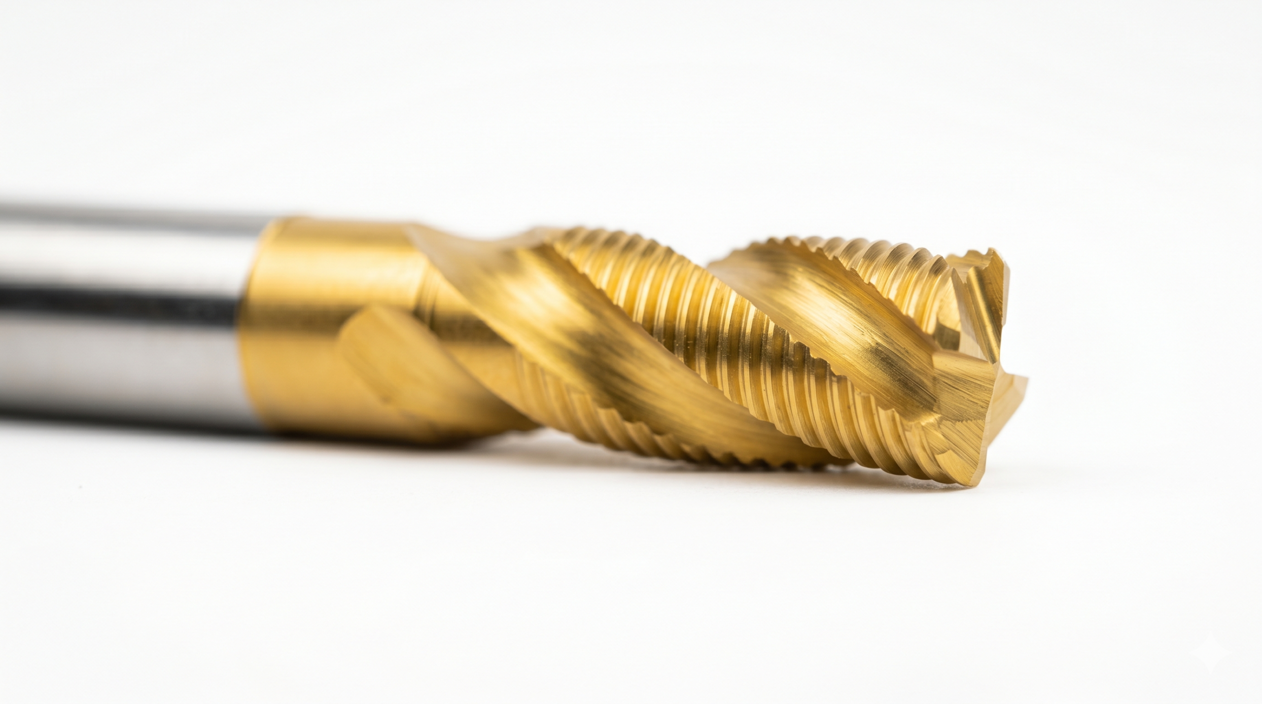
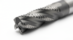
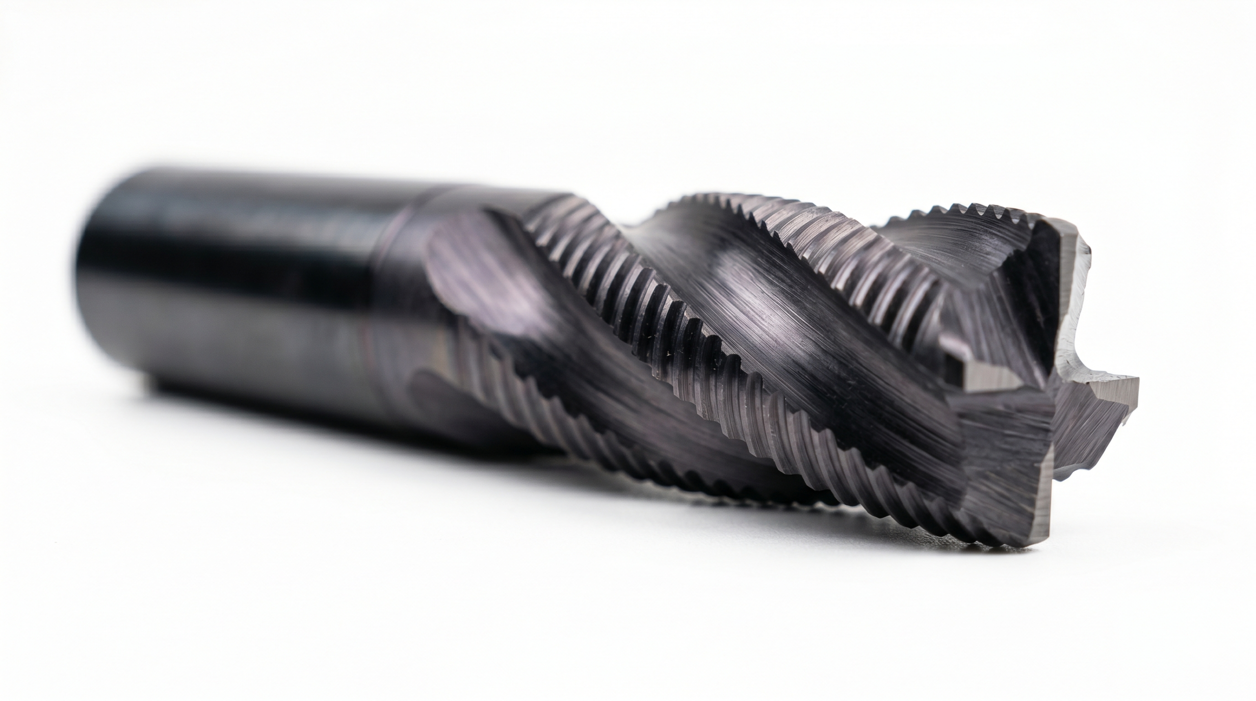
Roughing End Mills
Roughing end mills, also called corncob mills, carry a serrated or wave-form profile along their cutting edges. This serration fractures the chip into short segments as it forms, rather than allowing a single continuous chip to accumulate in the gullet. The result is reduced cutting force per tooth, lower vibration tendency, and higher material removal rates compared to a standard end mill at equivalent cutting parameters. The trade-off is a coarse, stepped surface finish that requires a subsequent finishing pass with a standard end mill.

Slot Drills
Slot drills are 2-flute end mills designed specifically for plunge entry and slot cutting. The 2-flute geometry maximizes chip gullet volume, which is critical in slotting operations where the tool is fully enclosed by workpiece material on both sides and chips have limited room to escape. Using a 4-flute end mill in a full-width slot risks packing the gullet with chips and either stalling the spindle or breaking the tool. Slot drills prevent this by sacrificing surface finish quality for the chip clearance the operation demands.

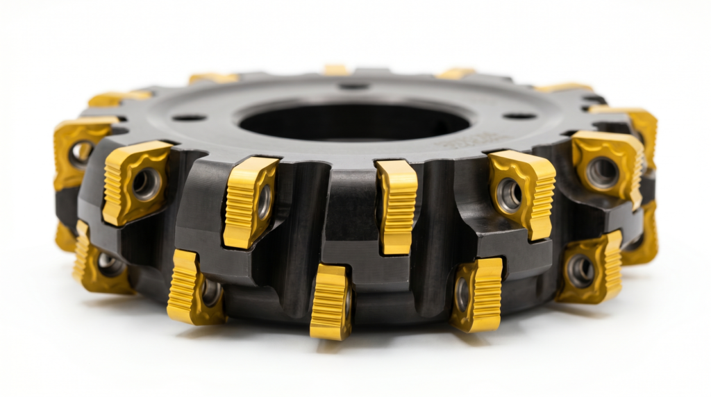
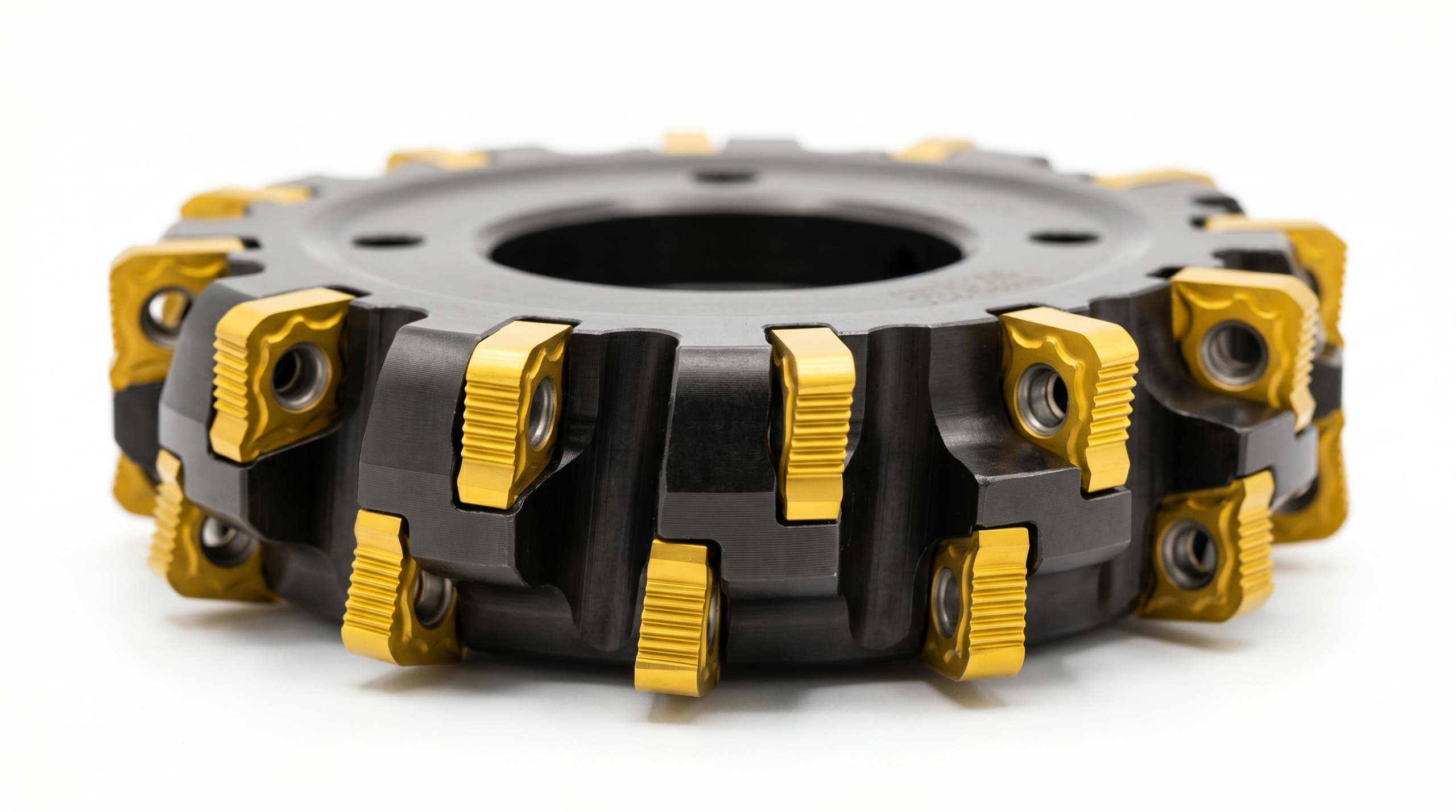
Face Mills
The face mill is the workhorse of flat surface generation. Rather than a helix angle, the dominant geometry parameter is the entering angle, also called the lead angle (KAPR): the angle between the main cutting edge and the machined surface. The large tool diameters (typically 50 to 200 mm), high insert density, and rigid, short-reach bodies make face milling the most productive method for generating flat surfaces on large workpieces.
| KAPR (Entering Angle) | Chip Thickness | Force Direction | Insert Life | Shoulder Capability |
| 45° | Thin (load spread over longer edge) | Split axial/radial | Longest | No true square shoulder |
| 75° | Moderate | Majority radial | Moderate | Near-square shoulder |
| 90° | Full (concentrated on edge) | Fully radial | Shortest | True square shoulder |
Shell Mills
Shell mills are face mills with a central bore that mounts onto a separate arbor. The arbor can be shared between different diameter shell mill bodies, which reduces tooling cost in shops that run multiple diameters on the same machine spindle. Functionally, they are identical to face mills; the classification refers strictly to the mounting configuration.
Fly Cutters
A fly cutter uses a single replaceable high-speed steel (HSS) or carbide tool bit mounted in a rotating body. The single-point geometry makes it extremely versatile and low-cost to set up, but the absence of multiple inserts limits productivity severely. Cycle times at equivalent material removal rates are four to twelve times longer than an equivalent insert face mill. Fly cutters are appropriate for low-volume, low-budget work, toolroom use, and situations where the required face diameter exceeds what insert face mills can practically cover.
Form and Profile Milling
Form and profile mills carry a cutting edge ground to a specific shape. Each cutter in this family performs one job determined entirely by its geometry. Substituting a tool from a different family will not produce the correct feature.
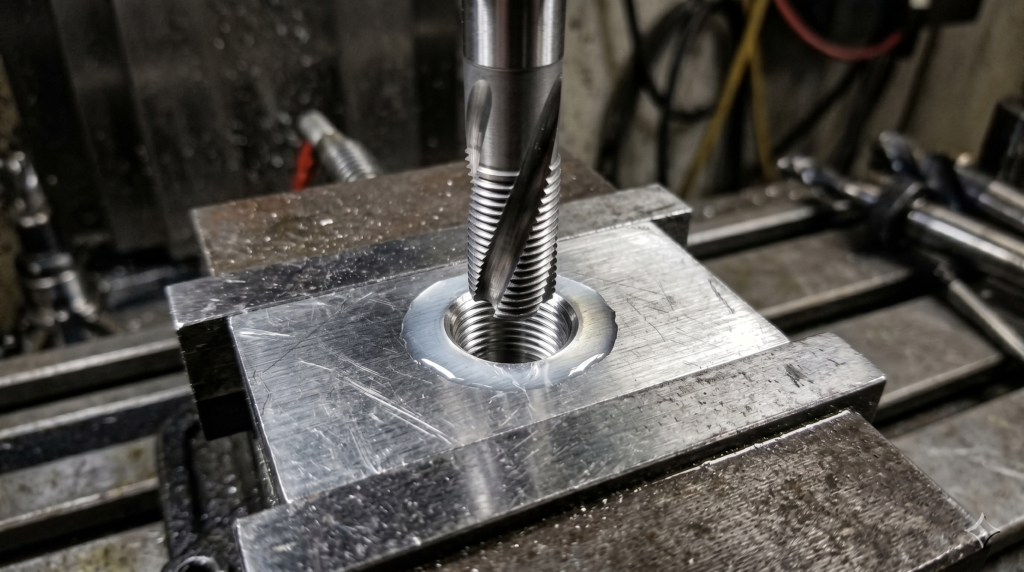
Thread Mills
Thread mills have the thread-form profile ground into their side geometry. They are smaller in diameter than the hole being threaded and travel in a helical interpolation path around the inside of the hole to cut the thread. One thread mill cuts threads of any depth at the matching pitch, which gives it an advantage over taps in blind hole applications where a tap risks bottoming and breaking. Thread mills also work on hardened materials that cannot be tapped, and they produce no broken-tap scrap-out risk.

When specifying threaded features, verify tap drill diameter and thread engagement length early in the design process using the thread and tap drill size calculator before committing to a thread specification on the engineering drawing.
T-Slot Cutters
T-slot cutters require a pre-machined vertical access slot before they can be deployed. The cutter enters through the access slot, then traverses laterally to widen the base of the channel to the cutting head’s diameter, creating the T-profile. The primary industrial application is machine tool table slots designed to accept T-bolt heads for workholding fixture attachment.
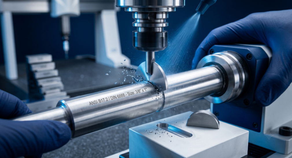
Woodruff Key Cutters
Woodruff key cutters are specialized disc-form tools for machining the semicircular key slots specified in ANSI B17.2 and DIN 6888 for shaft and bore assemblies. Geometrically, they are very similar to T-slot cutters, but their dimensions are standardized to match the semicircular key dimensions defined in the relevant standards. Specifying a non-standard slot depth or width forces a custom tool order, which adds procurement lead time and cost.
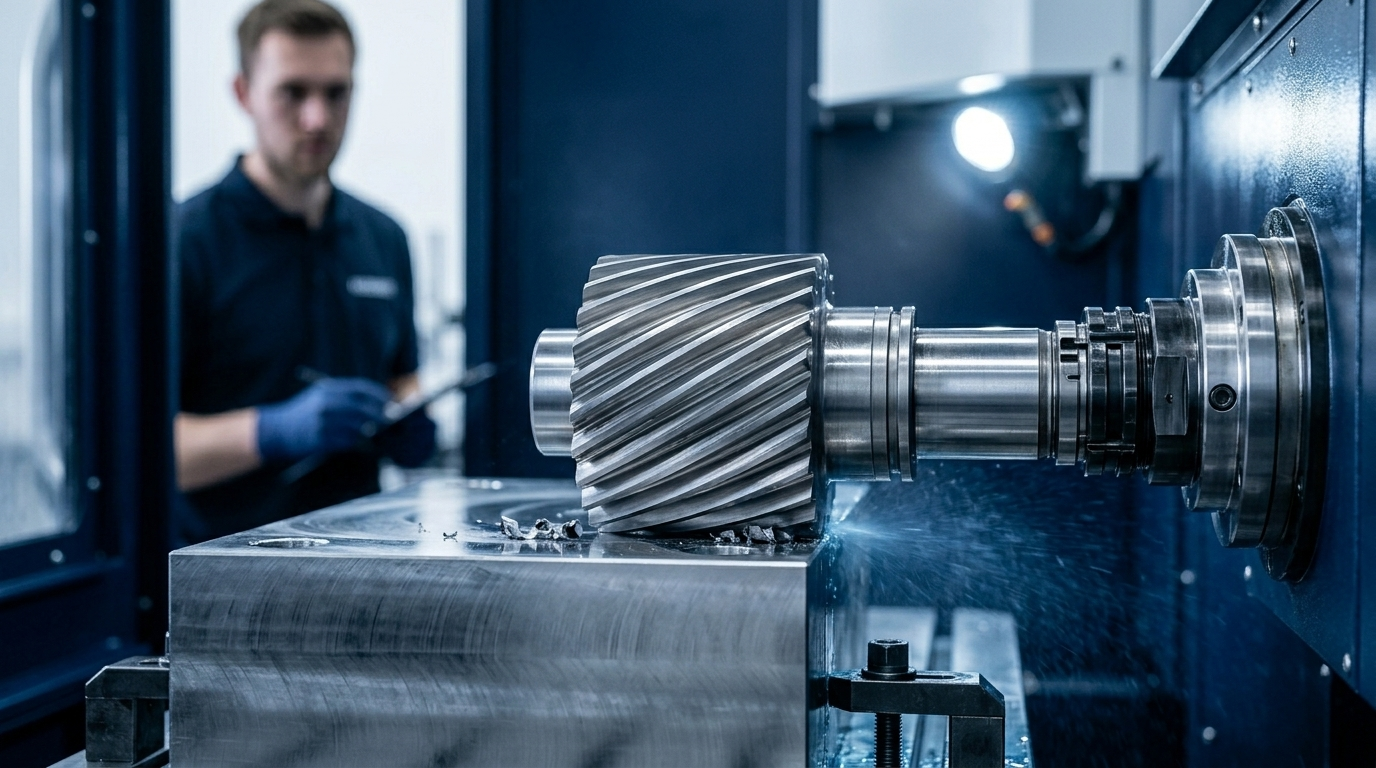
Involute Gear Cutters
Involute gear cutters are form-relieved disc tools ground to the exact involute tooth profile of the target gear. They operate on a horizontal dividing head, cutting one tooth space at a time. The tool must be indexed to the correct number for the target tooth count range: a single cutter covers a range of tooth counts, not a single value. Involute gear cutters are suited to one-offs and small batch production. High-volume gear production uses gear hobbing or gear grinding, not form-milling.

Peripheral and Plain Milling
Peripheral and plain milling cutters cut on their periphery, parallel to the spindle axis, mounted on a horizontal arbor. This family is the legacy tooling from the horizontal milling era. Vertical machining centers with indexable face mills have largely displaced them for flat surface work. They remain relevant in shops running horizontal spindle equipment and for specific straddle milling applications.
Slab Mills
Slab mills are wide cylindrical cutters with helical teeth around the full periphery. Mounted on a horizontal arbor, they face large flat surfaces in a single wide pass, which was the dominant flat-surface productivity method before indexable insert face mills became standard. In shops still running horizontal milling equipment, slab mills remain efficient for high-stock-removal passes on wide, flat billets.

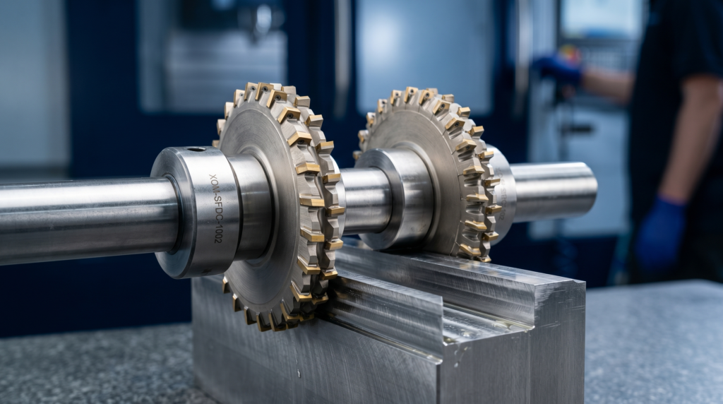
Side-and-Face Cutters
Side-and-face cutters are disc-shaped tools with teeth on the periphery and on both side faces. Mounted on a horizontal arbor, they are used for slotting and straddle milling, where two cutters on the same arbor machine both sides of a workpiece simultaneously.
The ability to set the two-cutter distance precisely with spacers makes this method highly repeatable for parallel-sided slot and groove features in batch production.

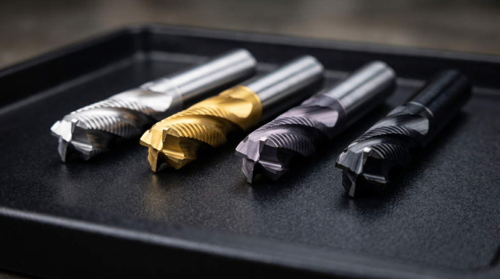
Cutter Materials and Coatings
The substrate determines how hot the cutter can run before losing its hardness. The coating multiplies tool life by reducing friction and slowing chemical wear at the cutting edge. Substrate and coating must be selected together, because mismatching them (a high-temperature coating on a low-temperature substrate, for example) gives no benefit while adding cost.
Substrate Materials
| Substrate | Max Operating Temp | Hot Hardness | Best For | Key Limitation |
| High-speed steel (HSS) | ~600°C | Low | General-purpose, custom-ground shapes | Soft above 600°C, low productivity |
| Cobalt HSS (M35, M42) | ~675°C | Moderate | Stainless steel, titanium | Modest improvement over plain HSS |
| Cemented carbide | ~900°C | High | Production milling: steel, stainless, aluminum | Brittle, intolerant of impact loading |
| Cutting ceramic (Al₂O₃, Si₃N₄) | ~1,200°C | Very high | Cast iron, nickel superalloys at high speed | Very brittle, no interrupted cuts |
| Cubic boron nitride (CBN) | ~1,400°C | Highest (non-diamond) | Hardened steel finish milling | Expensive, brazed tip format only |
| Polycrystalline diamond (PCD) | ~700°C | Highest | Aluminum, copper, composites | Reverts to graphite above 700°C, cannot cut ferrous |
High-speed steel (HSS) remains relevant for custom-ground tools, form tools made in-house, and low-volume work where carbide’s brittleness and cost are not justified. Cemented carbide is the dominant substrate for production CNC milling across steel, stainless, and aluminum. CBN and PCD are application-specific premium options with a narrow scope of correct use.
Coatings
Coatings protect the substrate surface from heat, abrasion, and chemical attack. The correct coating for a given application is determined by the workpiece material and the cutting temperature that material generates, not by the substrate alone.

| Coating | Max Temp | Primary Function | Correct Application |
| TiN (titanium nitride) | ~600°C | Surface hardness, low friction | HSS tooling, moderate-speed carbide, soft non-ferrous |
| TiAlN / AlTiN (titanium aluminum nitride) | ~800°C | Self-healing alumina barrier layer | Steel and stainless milling at production speeds |
| AlCrN (aluminum chromium nitride) | ~1,100°C | Highest oxidation resistance of standard coatings | Hardened steel, high-temperature alloys |
| DLC (diamond-like carbon) | ~400°C | Extreme friction reduction | Aluminum, copper, plastics: prevents built-up edge |
TiAlN and AlTiN are the standard coatings for solid carbide end mills in steel milling because the alumina layer they form at elevated temperatures improves protection as the tool heats up, covering the substrate precisely in the temperature range where cemented carbide is most vulnerable. AlCrN extends this principle to harder materials and higher temperatures. DLC is selected specifically to prevent the adhesion and built-up edge problems that aluminum and other sticky non-ferrous materials cause on uncoated or TiN-coated tools.
Cutting Parameters That Govern Tool Selection
Three parameters drive the cutting tool choice – cutting speed, feed per tooth and depth of cut. Sandvik has all relevant milling formulas listed for calculations.
Cutting Speed
Cutting speed (Vc) is the surface speed of the cutting edge at the cutter’s outer diameter, measured in meters per minute. Correct cutting speed is a function of two variables: the workpiece material and the tool substrate. Too high a speed generates excessive heat, softening the substrate and accelerating wear. Too low a speed causes rubbing rather than cutting, which also generates heat and shortens tool life.
| Workpiece Material | Typical Vc Range (m/min) – Carbide Tool |
| Aluminum alloys | 200 to 600 |
| Mild steel | 80 to 200 |
| Stainless steel (austenitic) | 50 to 120 |
| Titanium alloys | 30 to 80 |
| Hardened steel (45–60 HRC) | 50 to 150 (CBN) |
| Cast iron | 100 to 300 |
| Nickel superalloys | 15 to 50 |
Feed per Tooth
Feed per tooth (fz) sets the chip load: how much material each individual tooth removes per revolution. Too low a chip load thins the chip below its ideal cross-section, concentrating heat generation into a smaller volume of material and accelerating tool wear. Too high a chip load exceeds the tool’s structural capacity, causing deflection, chatter, or breakage. Chip load is not interchangeable with feed rate: feed rate (mm/min) = fz × number of flutes × RPM.
Depth of Cut
Depth of cut has two independent directions: axial (how far the cutter plunges into the workpiece) and radial (how much of the cutter diameter is engaged sideways). Radial engagement is the more aggressive of the two variables for heat generation: a cutter with 100% radial engagement (full-width slotting) has each tooth in contact with the workpiece for half of every revolution, which generates sustained, concentrated heat. A light radial pass uses a larger axial depth to compensate, spreading the load across the full flute length while keeping each tooth’s time-in-cut short.
| Operation Type | Radial Engagement | Axial Engagement | Heat Level | Correct Application |
| Slotting | 100% (full width) | Shallow (0.5x to 1x D) | High | Slot cutting only, use 2-flute |
| Conventional roughing | 30% to 60% D | Moderate (1x to 1.5x D) | Moderate | General material removal |
| High-efficiency milling (HEM) | 5% to 15% D | Deep (3x to 5x D) | Low | Maximum tool life, fast cycle times |
| Finishing | 5% to 10% D | Full depth of feature | Low | Surface quality, dimensional accuracy |
Design for Manufacturability: Designing with the Cutter in Mind
Every design feature that falls outside the standard cutter catalog creates a sourcing problem that becomes a cost and lead time liability.
The following constraints are direct outputs of cutter geometry and must be considered at the drawing stage.
| Design Feature | Cutter Constraint | DfM Rule |
| Internal pocket corner radius | Must equal or exceed the cutter radius. | Specify the smallest acceptable radius, not zero. An internal radius of 0 is physically impossible to mill. |
| Slot width | Cannot be narrower than the smallest available cutter diameter. | Standard slot widths (3, 4, 5, 6, 8, 10, 12, 16, 20 mm) eliminate custom tooling premiums. |
| Pocket depth | Limited by the L:D ratio of the cutter. | Pocket depth should ideally not exceed 4x the corner radius specified. |
| Thread specification | Determined by available tap and thread mill sizes. | Use metric (ISO) or unified (UNC/UNF) standard threads. Cross-verify drill sizes early. |
| Chamfer angle | Standard chamfer mills cover 30°, 45°, and 60°. | Non-standard angles require custom tooling setup. Default to 45° wherever possible. |
| T-slot and dovetail geometry | Requires a pre-machined vertical access slot. | Include access slot dimensions on the drawing, matched to available cutter entry diameters. |
| Woodruff key slot | Must match ANSI B17.2 or DIN 6888 standard sizes. | Specify a standard key number. Non-standard widths force an expensive custom tool order. |
Designs that align with standard cutter diameters, radii, chamfer angles, and thread pitches move through quoting and setup faster and with fewer engineering change requests. For features with tight dimensional requirements that interact with mating parts, tolerances should be defined using standard limits and fits to confirm that the specified fit class is achievable with standard CNC milling process capability before the drawing is released.
The practical outcome of understanding milling cutter constraints is fewer drawing revisions, faster quoting cycles, and parts that reach first-article inspection without tooling-driven surprises.

Comment(0)