 Europe
  Türkiye
How to call out helicoils or inserts on a drawing?
M
Hey,
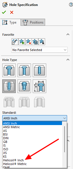
My aluminum part needs reinforced threads, so I’m looking at using Helicoils or possibly another type of insert if the machinist has a better suggestion (I’ll have my part produced by an external manufacturer). Right now, I’ve got the bolt spec and I’ve sized the hole to match the minor diameter from the Helicoil standard, but I’m not sure if that’s the right way to show it on the drawing.
Should I just note the Helicoil size and standard, or is there a better way to indicate that an insert is needed? Would a machinist prefer a fully dimensioned hole spec, or is a general note enough?
Suggested Topics
Topic
Replies
Views
Activity
High resolution scan to fully transparent object?
Is there a possibillity to make my handmade objects into aquaria? I need fulley transparent material UV resistant, no scratches very strong 1 meter in height, what kind of meterial would i need and... read more
3
139
Jul 08
Flatness GD&T for 6061 plates
For a mounting plate for a precision sensor (about 200 mm × 200 mm) I was going to call out a flatness of 0.05 mm, but my senior engineer says that’s overkill and will double the machining... read more
3
3.2k
Mar 14
ISO 2768-mK vs specific tolerances
Hey guys, I’m getting some pushback from our shop lead. I’ve been dimensioning every single feature on a new manifold block because I’m paranoid about fitment, but he says the drawing is "unreadable" and... read more
2
3.8k
Mar 14
Thermal expansion modelling for a braced rectangular steel tank
hi, for a welded steel coolant reservoir for a test stand - 4 m × 2 m × 1.5 m with internal bracing I need to account for thermal expansion. Fluid runs at 80–90... read more
2
2.6k
Feb 04
Designing holes for M3 threaded inserts in an ABS enclosure
Hi! In my design for a small ABS enclosure for an onboard sensor module I want to switch from molded bosses to heat-set M3 inserts for the lid screws. Before I finalize CAD, what... read more
1
1.3k
Dec 23