 Europe
  Türkiye


Tolerances are often confused with accuracy and precision. In 3D printing technology, these terms are distinct and should never be used interchangeably. Tolerances define how precise the designer needs to be. In other words, it is the amount of wiggle room allowed in a design or manufacturing, which depends on individual or industry standards.
When you mention accuracy, it simply refers to how consistent your dimensions are compared to the actual value. In this case, the true value is the dimensions of the digitized 3D printing model. On the other hand, accuracy defines how close the dimensions of 3D-printed parts are to those of the model.
Tolerances in 3D Printing: What to Expect
Different 3D printing technologies offer varying capabilities when it comes to tolerances. The achievable accuracy depends on the part size, chosen material, and geometry—especially if the design is bulky, as this can lead to more shrinkage.
Below is a quick overview of the general tolerances offered by Xometry for the most commonly used 3D printing technologies. These values are indicative and can vary depending on factors such as part size, material choice, and geometry.
| 3D Printing Technology | Tolerances |
| MJF | ± 0.3% (± 0.2 mm) |
| SLS | ± 0.3% (± 0.3 mm) |
| SLA | ± 0.5% (± 0.2 mm) |
| FDM | ± 0.5% (± 0.5 mm) |
| Carbon DLS | ± 0.1% (± 0.1 mm) |
| DMLS | ± 0.2% (±0.1 – 0.2 mm) |
| Polyjet | ±0.1 mm for the first dozens of mm is typical, plus ±0.05 mm for every mm thereafter |
In the following sections, we’ll explore the typical tolerances achievable with each 3D printing technology in more detail.
MJF 3D Printing Tolerances
HP Multi Jet Fusion (MJF) is one of the most cost-effective 3D printing technologies offering fine tolerances. It works by applying a fusing agent to powdered material, followed by a heat source that systematically cures each layer. Heated build chambers raise the overall powder temperature, minimizing warping and shrinkage while allowing gradual temperature changes that enhance dimensional accuracy.
However, heat buildup—especially from the infrared lamps used during printing—can still lead to thermal stresses. Thicker geometries, broad surfaces, and uneven wall thicknesses are more prone to warping or twisting due to shrinkage. To reduce these risks, it’s best to follow design guidelines similar to those used for injection-moulded parts.
| Parameter | Value |
| Tolerance | ± 0.3% (lower limit: ± 0.3 mm) Pro tip: For tighter tolerances, PA 12 glass-filled is recommended. |
| Shrinkage/Warping | Shrinkage usually occurs in the 2 – 3% range. However, most MJF printers allow for this in the design |
| Build Volume | Up to 380 x 284 x 380 mm, while we normally recommend the maximum size of 356 x 280 x 356 mm |
| Layer Thickness | ~0.08 mm |
| Minimum Feature Size | Minimum 0.5 mm, 0.7 mm is recommended |
| Support Structure | Not required |


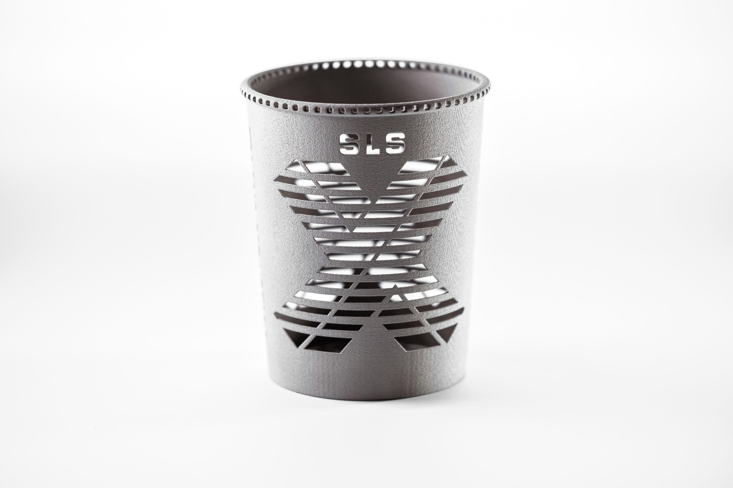
SLS 3D Printing Tolerances
Selective Laser Sintering (SLS) is similar to MJF in many aspects. The only difference is that SLS uses a CO2 laser for heating the polymer powder instead of a heat lamp. Warping and shrinkage are problems in MJF and SLS. This is mitigated in SLS by leaving the 3D-printed parts in the powder to gradually cool.
| Parameter | Value |
| Tolerance | ± 0.3% (± 0.3 mm for 100 mm) Pro tip: For tighter tolerances, PA 12 glass-filled is recommended. |
| Shrinkage/Warping | Shrinkage typically ranges from 3% to 3.5%. Large flat surfaces are particularly prone to warping |
| Build Volume | Up to 340 x 340 x 605 mm, but usually, we recommend the maximum size of 320 x 320 x 580 mm |
| Layer Thickness | ~0.1 mm and for water-tight parts 1.5 mm, when the wall thickness is higher |
| Minimum Feature Size | Minimum 0.5 mm, 0.75 mm is recommended |
| Support Structure | Not required |

SLA 3D Printing Tolerances
Stereolithography, or SLA, is a preferred 3D printing technology where higher accuracy and finer tolerances are vital. The materials chosen for this process (polypropylene, ABS, polycarbonate, etc.) are cured and processed with UV. However, materials with high flexural characteristics are not ideal as they are prone to warping.
This technology also requires the parts being 3D-printed to be anchored to the build plate and any features with angles lower than 45o to be supported.
| Parameter | Value |
| Tolerance | ± 0.5% (± 0.20 mm) |
| Shrinkage/Warping | Unsupported spans are likely to experience warping |
| Build Volume | Up to 736 x 635 x 533 mm |
| Layer Thickness | ~ 0.02 mm |
| Minimum Feature Size | 0.1 mm |
| Support Structrue | Yes, for overhanging features |

FDM 3D Printing Tolerances
Fused Deposition Modeling (FDM) produces parts by extruding thermoplastic material onto a build plate, layer by layer. It is well-suited for larger parts, mechanical geometries, and applications that don’t require ultra-fine details. FDM is widely used across industries due to its versatility and affordability.
Like SLA, FDM requires support structures, and post-processing can introduce dimensional inaccuracies, especially in heavily supported areas. Additionally, narrow features may not be accurately resolved because of the nozzle width. Shrinkage begins immediately as the material cools after deposition, and tolerances can vary significantly between desktop and industrial FDM printers.
| Parameter | Value |
| Dimensional Tolerance | Prototyping (desktop): ± 0.5% (lower limit: ± 0.5 mm)
Industrial: ± 0.15% (lower limit: ± 0.2 mm) |
| Shrinkage/Warping | Materials like PLA exhibit low shrinkage (0.3%–0.5%), whereas others like Nylon 12 can shrink up to 2%, and PVDF up to 4% |
| Build Volume | Up to 914 x 610 x 914 mm. |
| Layer Thickness | ~0.05-0.3 mm |
| Minimum Feature Size | Up to 0.2 mm. |
| Support Structure | Yes, for overhanging features |


DMLS 3D Printing Tolerances
Direct Metal Laser Sintering (DMLS) is used to produce near pore-free metal parts with a surface roughness of around 20 micrometers. The process involves high heat, which often leads to shrinkage and warpage. Unlike plastics, metals have different heat conductivity and shrinkage rates, which must be considered during design to ensure dimensional accuracy.
| Parameter | Value |
| Tolerance | ± 0.2% (± 0.1 – 0.2 mm) |
| Shrinkage/Warping | High heat during the process can cause shrinkage and warping |
| Build Volume | 250 x 250 x 325 mm |
| Layer Thickness | 0.02 – 0.08 mm depending on the material. |
| Minimum Feature Size | 0.75 mm for cosmetic features, 1.5 mm for structural features. |
| Support Structure | Yes, for overhanging features |

Polyjet 3D Printing Tolerances
PolyJet is one of the most accurate 3D printing technologies, offering the finest tolerances and exceptional detail resolution. It uses rigid and rubber-like photopolymers without relying on heat, making it less prone to warpage and shrinkage. However, the materials are less robust than the thermoplastics used in FDM or SLS.
| Parameter | Value |
| Tolerance | ± 0.05-0.1 mm for 100 mm |
| Shrinkage/Warping | Minimal due to the UV curing process; however, large flat areas may experience slight warping |
| Build Volume | Up to 490 mm x 391 mm x 200 mm. |
| Layer Thickness | 0.004 mm |
| Minimum Feature Size | 1.2 mm or greater for rigid. 2 mm or greater for rubber-like. |
| Support Structure | Yes, for overhanging features |


Carbon DLS 3D Printing Tolerances
Carbon DLS is a highly accurate 3D printing technology that uses thermally cured engineering resins. These materials include urethane-based options such as FPU (flexible), RPU (rigid), EPU (elastomeric), and SIL, which mimics silicone. While Carbon DLS delivers fine details and strong parts, the curing process can introduce some shrinkage.
| Parameter | Value |
| Tolerance | ±0.1% (± 0.1 mm for 100 mm) |
| Shrinkage/Warping | The curing process can introduce some shrinkage |
| Build Volume | Up to 119 x 189 x 300 mm. Recommended size: Within 100 x 100 x 150 mm |
| Layer Thickness | ~0.1 mm |
| Minimum Feature Size | Minimum 1 mm is recommended |
| Support Structure | Yes, for overhanging features |
Impact of Post-Processing on Tolerances
Most technologies produce support structures. Removal of the supports not only affects the surface finish but also sometimes leads to material removal at that point. This creates inaccuracy in the dimensions.
Finishing processes like sanding can be used to cut out extra dimensions whereas techniques like coating and painting can add little to the dimensions. In DMLS, sometimes 1–2 mm of additional material is applied to significant surfaces and is machined accordingly after printing. This is a way to correct the dimensions and achieve tight tolerances.
Factors Affecting Tolerances in 3D Printing Technology
In 3D printing, the major factors influencing the tolerances are:
- Material shrinkage (change in volume from a change in state from liquid to solid)
- Layer thickness
- Minimum feature size
- Build size (maximum size of the part to be printed, depending on the technology)
1. Material Shrinkage
The build material used in the 3D printing processes includes thermoplastics filaments, powders, resins, liquid photopolymers and metal powder. All these materials have a varying degree of shrinkage. As a principle of 3D printing, the polymers naturally shrink when they are cooled and solidified during the printing process. The rate of shrinkage is specific to a definite material.
| Factor | Impact on Shrinkage and Tolerance | Practical Solutions |
| Material Type | Different materials shrink at different rates. For instance, Nylon shrinks more than PLA. | Use material-specific design rules; choose low-shrink materials such as PLA, PETG, or photopolymer resins for high-precision parts. |
| Part Geometry | Large, flat, or thick sections are prone to warping and distortion. | Break up large surfaces with ribs; avoid sharp corners; reduce part mass if possible. |
| Wall Thickness | Uneven walls cool at different rates, causing internal stress and shape deformation. | Keep wall thickness consistent; gradually transition between thick and thin sections. |
2. Layer Thickness
Layer thickness, also called vertical resolution, affects how accurate a part is in the Z-direction. Its impact is especially visible in processes like FDM, SLA, and PolyJet, where parts are built directly on a bed. Below is a breakdown of how layer thickness influences print quality across technologies:
| Technology | Typical Layer Thickness | Impact on Accuracy | Considerations |
| FDM | 0.05–0.3 mm | Large initial layer (often >100% extrusion) can cause oversize base; stair-stepping visible on curves | Avoid ultra-fine features on curves or base surfaces |
| SLS | 0.10–1.50 mm | Layer height is pre-set; stair-stepping less visible due to powder fusion | Not ideal for curved detail but consistent dimensional results |
| MJF | 0.08 mm | Consistent Z-resolution with minimal visible stepping | Very stable process; suited for functional parts with good dimensional accuracy |
| SLA | 0.02 mm | Good Z-resolution, but warping can occur from curing stress | Use supports to stabilize tall parts |
| DMLS | 0.02–0.08 mm | Very fine layers reduce stepping, but thermal stresses may affect flatness | Use optimized supports |
| Polyjet | 0.04 mm | Excellent Z accuracy; minimal stair-stepping | Ideal for smooth surfaces and fine details |
3. Minimum Feature Size
Minimum feature size refers to the smallest detail a 3D printer can reliably produce. It depends on both the printing technology and machine-specific parameters such as nozzle diameter, layer thickness, and laser beam size.
For FDM, the feature size depends on nozzle and layer height:
- X-Y Resolution: Determined by the nozzle diameter. A smaller nozzle allows finer details on horizontal surfaces.
- Z Resolution: Controlled by layer thickness. Thinner layers allow better resolution on vertical and sloped surfaces.
- For example, a 0.4 mm nozzle typically prints features no smaller than 0.4–0.5 mm in X-Y. Smaller text or grooves are better printed with a 0.2 mm nozzle.
- Note: Feature detail varies based on part orientation. Details on the top surface will be sharper than those on vertical sides.
Powder-based and resin technologies rely on laser beam or light source diameter and material characteristics for resolution:
- Laser/light spot size: Defines the smallest X-Y feature printable.
- Layer height: Affects Z-resolution, just like in FDM.
- Material reuse: In powder-based methods (MJF, SLS, DMLS), reused powder becomes less spherical over time, reducing resolution consistency and dimensional reliability.
4. Build Size
Build size refers to the maximum overall size of the part that can be manufactured by a printer or the maximum size that is fitted onto a build area in a printer. The bigger the part, the more time required for it to cure or cool down. During this process, a lot of shrinkage and warpage takes place due to uneven cooling.
Big parts also require a lot of support structures (depends on design and process though). When removed, it also affects the surface quality.
Sourcing 3D Prints With Tighter Tolerances
Achieving tight tolerances in 3D printing is not just about selecting the right technology—it’s about understanding the interaction between material behavior, printer capability, part geometry, and process settings. Designers should account for tolerance requirements early in the CAD stage, applying process-specific design rules and planning for post-processing where needed. When precision is critical, choosing stable materials, and reliable technologies like SLA, PolyJet, or DMLS can make a significant difference.
Alternatively, working with an experienced manufacturing partner gives access to industrial-grade machines, controlled environments, and expert feedback—ensuring your parts meet both functional and dimensional specifications. Xometry offers custom industrial 3D printing services with a wide range of technologies and materials, dimensional inspection options, and expert support to help you achieve the precision your project demands.


Comment(0)