CNC machining and injection molding are prominent options when producing mechanical parts for the electronics industry, with their own strengths and considerations. CNC machining offers precision and flexibility for custom parts and short lead times, while injection molding boasts efficiency and scalability. Understanding the intricacies of these technologies, including material compatibility, design flexibility and production capacity, empowers engineers and product designers to select the optimal manufacturing process.
Why Choose CNC Machining for Electronics?
The choice of manufacturing technology depends on several factors, like design complexity or production volume. But most importantly, the functionality and reliability of electronic devices must be guaranteed, which makes high-precision production essential. Components such as metal housings, connectors or heat sinks, for example, require very precise tolerances to fit perfectly into electronic assemblies. This means tight tolerances and process repeatability are essential.
CNC machining is the technology that allows us to achieve the best tolerances and to work with an almost infinite range of materials (all we need is a block or bar of the material). This enables us to design products that are well-adapted to the environment in which the device will be used.
While sheet metal fabrication is ideal for producing cost-effective parts with consistent thickness that can be cut or folded, it tends to be less precise. However, the materials available for sheet metal are similar to those for CNC machining, so the material characteristics and finishes mentioned below also apply to sheet forms.

Electromagnetic Compatibility of CNC Machining for Parts Like Connectors or Heat Sinks
Ensuring devices have electromagnetic compatibility is important. This means that devices like connectors and small copper components, must be designed in a way that they do not cause or experience electromagnetic interference with other devices. In practical terms, this means providing electromagnetic shielding, which involves, for example, enclosing the electronic device in a conductive material such as steel or aluminium to block electromagnetic waves. This can be done in machining and sheet metal work. Another option is to apply a conductive coating to the parts to simply create a conductive nickel layer is also an option.
CNC Machining Materials for Electronics
Complex support components can be made from a variety of materials, depending on the specific needs of the application and often the environment. Generally in a product for the electronics industry, the parts will have different functions, meaning a combination of mechanical, electrical and thermal properties are required.
For example, aluminium, such as the 6061 alloy, is useful as a heat sink. However, the need for insulation can be met with polymers (plastics), such as ABS, POM (Delrin/Acetal) or Polyamide (Nylon), which are very standard. PEEK, on the other hand, is much more expensive and rigid, although it also has insulating properties.
The table below compared the properties of the most commonly used materials in CNC machining for the electronics industry:
| Material | Type of material | Tensile strength (MPa) | HDT at 0.46 MPa (°C) | Hardness |
| Aluminium 6061 | Metal | 180 – 260 | N/A | 65 – 85HB |
| ABS | Polymer | 37 | 100 | 70D |
| POM (Delrin/Acetal) | Polymer | 66 – 67 | 156 | 81D |
| Nylon 6 / PA 6 | Polymer | 82 | 100 | 83D |
| PEEK | Polymer | 96 | 152 | 81D |
CNC Machining Surface Finishes for Aesthetic Parts like Housings and Casings
Surface finishes suitable for electronics are mainly applied to metals. Plastics are generally used for their intrinsic properties and do not require post-processing. Some of these surface finishes can increase the thickness of the part very slightly, such as powder coating or anodising. Conversely, electropolishing can very slightly reduce thickness. This is why it is important to specify the desired tolerances after post-processing on designs, so that these can be taken into account when the parts are manufactured.
There are three categories of surface finish:
- Finishes without chemical reaction
- Finishes with chemical reaction without electrolysis
- Finishes with electrolytic chemical reaction
Electrolysis involves using an electric current to cause a chemical reaction that does not occur naturally. To do this, parts are immersed in a conductive liquid and connected to a positive terminal. These parts act as anodes, losing electrons in the process. Electrolysis then forces oxidation of the parts, resulting in the desired chemical reaction.
| Surface finish | Type | Definition | Result | Suitable materials |
| Bead blasting | Without chemical reaction | Spraying a pressurised stream of small beads onto the surface of the part to remove burrs and imperfections, leaving a smooth finish | Uniform, satin-matt finish | All types of metals as well as plastics |
| Powder coating* | Without chemical reaction | Applying a dry, free-flowing powder to a part. Unlike normal liquid paint, which uses an evaporating solvent, powder coating is applied electrostatically and then cured under heat or UV light | Smoother surface, better corrosion resistance while protecting the part. Can provide an infinite range of possible colours | In general, the most suitable materials are aluminium and steel alloys |
| Passivation | With chemical reaction without electrolysis | Immersing the part in an acid bath to dissolve the iron and reinforce the protective action of the naturally formed chromium oxide. | Better corrosion resistance | Stainless steel |
| Chemical nickel plating | With chemical reaction without electrolysis | A uniform layer of nickel-phosphorus alloy is applied to the surface of the part. The part is then immersed in a bath containing nickel salts and phosphorus-reducing agents. The nickel plating is uniform, giving the part consistent current density and resistance | Greater resistance to mechanical wear, corrosion and increased electrical conductivity | All types of metals |
| Anodizing | With electrolytic chemical reaction | The part is dipped in an electrolyte, usually sulphuric acid, where it acts as an anode. Oxygen flows into the part and reacts to form aluminium oxide on the surface, which protects the part from corrosion. There are different types of anodising:
|
Protect against corrosion, extend the durability of parts, ensure non-conductivity and improve aesthetics. The finish can be glossy or matt if the part has been bead-blasted beforehand | Aluminium |
| Electropolishing | With electrolytic chemical reaction | The anode is a stainless steel part. The current acts more strongly on the micro-roughnesses of the surface, making it flatter and less rough. This technique is particularly useful for micro-deburring and removing any impurities that may have built up during part production. A further advantage is that the iron also dissolves more quickly on the surface, resulting in a very light protective layer of chromium oxide, similarly to passivation. | Smoothen surface. More or less shiny surface finish depending on the immersion duration | Stainless steel |
| Electrogalvanization / Electroplating | With electrolytic chemical reaction | This process involves depositing a thin layer of zinc on a metal part by electrolysis. | Enhanced corrosion resistance, shinny and uniform finish | All types of metals |
*ESD powder coatings are specially formulated to prevent static electricity buildup, which involves additional materials and manufacturing steps compared to regular powder coatings. Because of that can be more expensive and time-consuming than standard powder coating.
Why Choose Injection Molding for Electronics?
Injection molding is a popular manufacturing method for the production of enclosures, sockets and component holders due to its numerous advantages, particularly in producing high-quality, consistent, and cost-effective plastic parts:
- Competitive cost for mass production: Once the mold has been made, the cost per part is very low, and decreases with production volume. This makes it an economically viable option for the mass production of parts when designing electronic devices.
- Consistency and reproducibility: Once the tooling has been established, it can be used to produce identical parts. In general, tooling is guaranteed for several tens or hundreds of thousands, or even several million parts. The excellent reproducibility of the parts ensures uniform quality throughout the life of the product to be manufactured. ‘Family molds’ are also an option. In this case, different parts are produced at the same time in one tool, for example a left-hand part and a right-hand part. This method means that the assembly is constant over time.
- Dimensional accuracy: Injection molding can achieve very high tolerances to meet the design complexity of electronic devices. It can be used to manufacture parts of all sizes, particularly very small ones, with very fine details, but also with excellent surface quality. This can be an interesting option, because, in addition to their intrinsic functionality, parts often require a specific aesthetic appearance.

However, it is important to take into account the many constraints associated with the tooling, particularly with regard to removing parts from molds. In addition, to get optimum results during injection molding, the thickness of the part must be relatively constant (generally around 3 mm maximum) with thinner internal ribs being around half as thick as this. This is why the design must be specifically adapted for injection molding, which can limit the freedom of design compared to machining or 3D printing.
Specific Designs for Plastic Injection Molded Housings
Assemblies in the Final Product
Anticipating the assembly of electronic products is possible from as early as the design stage. For fairly standard assemblies, we can provide small bosses in the parts so that self-tapping screws can then be fitted, in particular to fix the electronic boards. It is also easy to design clip systems that work very well with injection molding.
Overmolding Injection Molding
There are different types of overmolding options with injection molding:
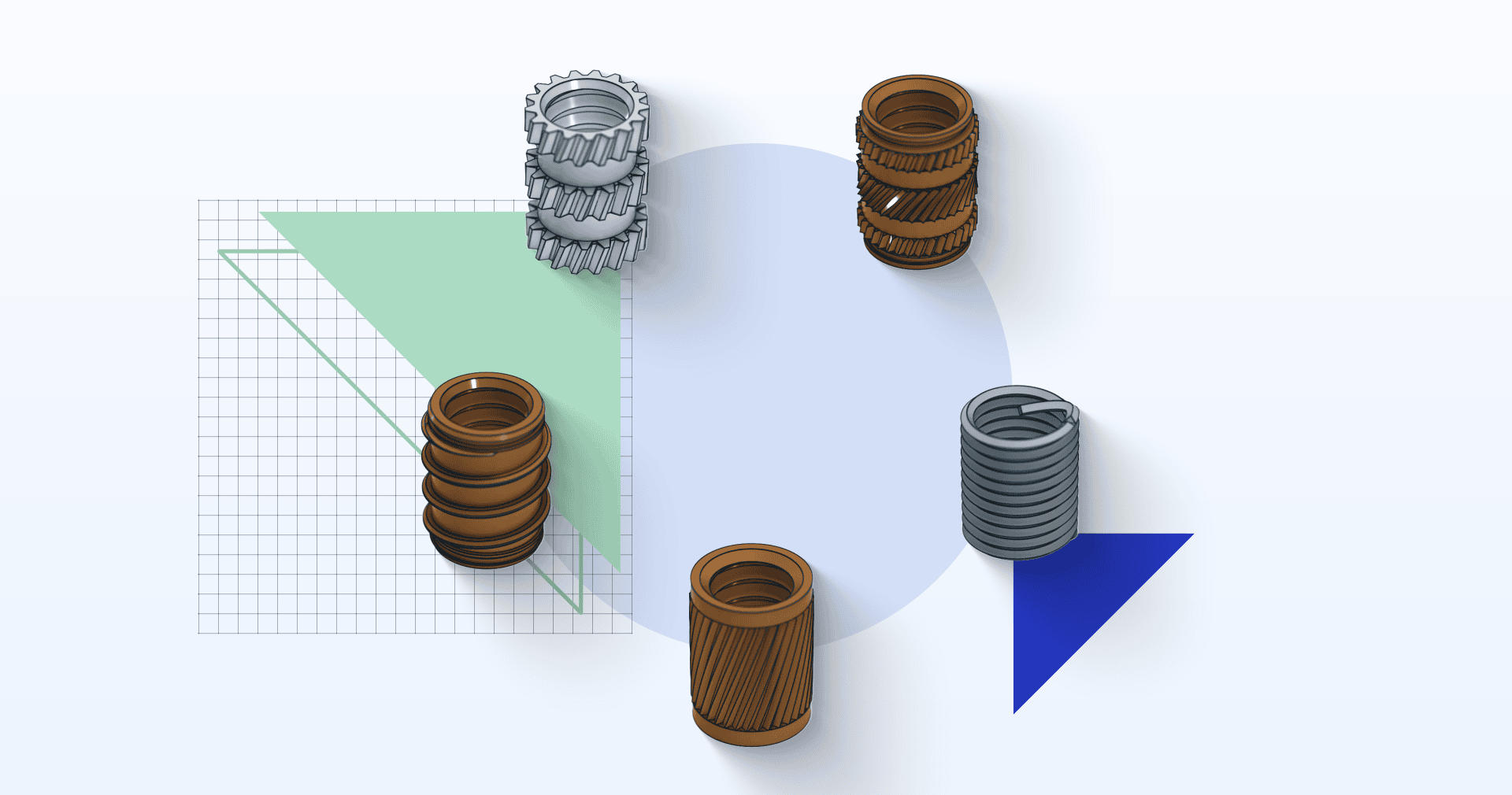
- The addition of threaded metal inserts provides an effective means of securing the other components. This method is particularly useful when the product requires repeated assembly and disassembly to ensure optimum durability–unlike self-tapping screws in plastic bosses.
- Other types of metal parts can also be overmolded, such as copper tabs. This allows all the small connector elements to be positioned very precisely. In this case, the purpose of overmolding is to seal and protect the electronic components and/or cables, ensuring their integrity and durability.
- Bi-material overmolding offers many possibilities, particularly when a rigid part is combined with a flexible part. This approach reduces the number of assembly steps, saving time and money in the design process. In addition, it can also improve the watertightness of products, offering better resistance to water, dust, humidity or pressure, for example in enclosures. It is also possible to integrate an area of soft buttons into a shell. The effectiveness of the overmolding will largely depend on the design of the part. For example, a mechanical bond between the two plastics or a chemical bond is possible. In this case, the choice of material is crucial, as not all materials are compatible.

Ultrasonic Welding
In terms of design, welded assemblies – particularly those using ultrasonic welding, also known as vibration welding – are increasingly of interest for injection molded parts. It is generally necessary to design the part with the weld bead already present. This technique is very useful for creating solid joints without damaging the components. In addition, as with overmolding, it allows two components to be permanently sealed.
Injection Molding Materials for Components like Connectors and Mounts
There is a very wide range of materials to choose from for injection molding projects, depending on electronic applications and environmental constraints. Electronic devices often require insulating and heat-resistant materials to ensure optimal and safe operation.
Here are some examples of commonly used materials:
- ABS and nylon (PA 6 and PA 66) are widely used in consumer electronics because of their versatility and relatively low cost.
- Polycarbonate (PC) is often preferred when transparency is required, while offering more technical characteristics.
- Elastomers such as TPE and TPV, with different Shore A hardnesses, are used to provide flexibility and possibly impact resistance.
- Materials such as PPS or PEEK offer excellent resistance to heat and fire, and have excellent mechanical properties.
The table below compares the mechanical and thermal properties of popular injection molding materials:
| Material | Type of material | Tensile strength (MPa) | HDT at 0.45 MPa (°C) | Hardness |
| ABS | Rigid polymer | 45 | 83 (1.8 MPa) | 110R (Rockwell) |
| Nylon 6, PA 6 | Rigid polymer | 85 | 177 | 80D |
| Nylon 66, PA 66 | Rigid polymer | 80 | 200 | N/A |
| Polycarbonate (PC) | Rigid polymer | 62 | 135 | N/A |
| PPS | Rigid polymer | 100 | 280 | N/A |
| TPE | Elastomer | 1.7 | N/A | 56A |
| TPV | Elastomer | 1.88 | N/A | 60A |
The values indicated in this table are generic and might differ from one provider to another. All values were taken from generic datasheets on ulprospector.com.
The choice of materials depends on the specific requirements of each application, whether in terms of mechanical properties, resistance to high temperatures, transparency or other characteristics.
Injection Molding Surface Finishes for Electronics
There are some differences compared to CNC machining, where the aim of the previously described finishes for metal parts is mainly to improve the characteristics of the parts through post-processing. In injection molding, the plastic already has the desired characteristics. Therefore, paint should be avoided, as it could flake off and potentially alter the flammability of the part.
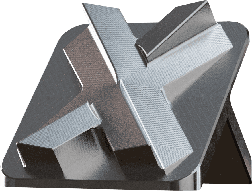
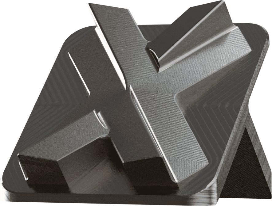
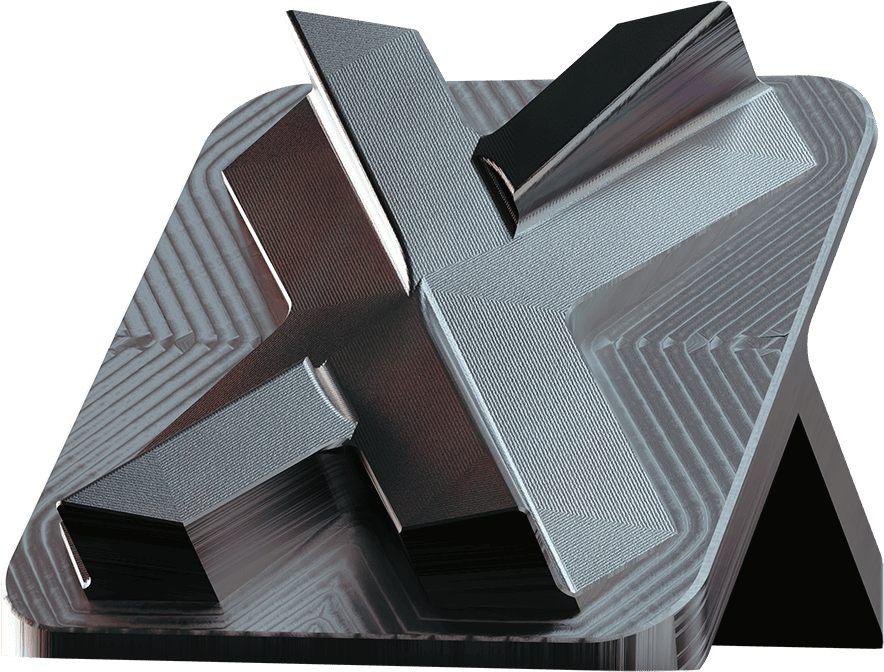
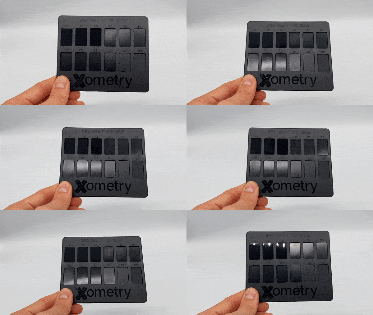
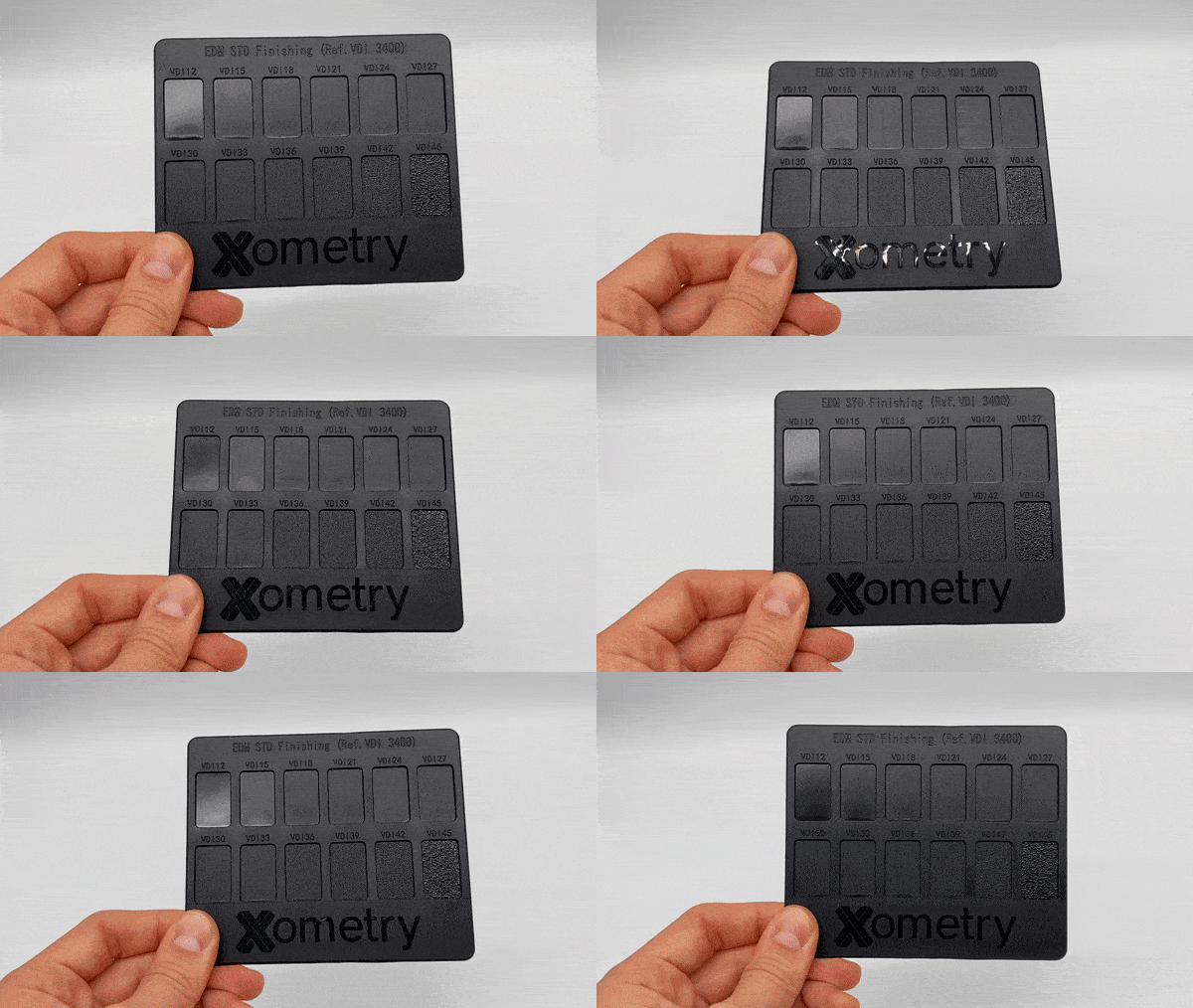
However, it is possible to obtain different surface finishes for aesthetic reasons or to facilitate assembly, depending on the roughness chosen. The mold itself is made before the parts are produced, to obtain different surface finishes, generally in accordance with SPI or VDI standards. This method means the surface finish of the parts is determined by the tooling and not by post-processing. Although, it is worth remembering that not all materials achieve the same results in terms of surface finish.
Nevertheless, certain post-processing methods are quite common in injection molding, particularly in electronics, for example, to mark button locations or to affix a logo. Different types of branding post-processes are also possible:
- Pad printing: An indirect photoengraving process used to print detailed, high-quality images on objects with uneven shapes and surfaces. This process is often reserved for large volumes.
- Screen printing: This is the leading solution for electronic boards designed to hold components. A metal foil is used as a stencil to apply the solder cream and thus distinguish the conductive areas of the printed circuit.
- EUV (Extreme Ultra Violet) lithography: This process enables printing in different colours (always depending on the specific characteristics of the plastics). Extreme ultraviolet light is used to create extremely fine patterns on silicon plates.
Specific Materials for Electronics
UL 94 Rated Materials
Flammability is often one of the most crucial criteria for electronics. Materials are generally tested in accordance with the UL 94 standard. This standard assesses the behaviour of plastics in the event of combustion, taking into account horizontal and vertical orientations and thicknesses, ranging from the least flame-retardant to the most flame-retardant. For example, if a material is classified as UL-94 V0, the thickness must be specified (e.g. 2mm). This thickness must be adhered to in order to benefit from a V0-grade flame-retardant characteristic.
In addition, it is recommended to stick to classic colours. It makes more sense to start with a material that is already V-0 white or V-0 black, rather than choosing a more exotic colour or using a masterbatch. Not only can the percentage of colourant added affect the characteristics of the part, but it is also much more difficult to achieve a precise shade with a V-0 material than with a conventional material.
In the case of very large production runs with a specific colour, it is possible to ask a materials manufacturer to produce a grade of customised material that has already been mass-coloured and classified as V-0.
The table below provides a list of UL 94 V-0 rated materials for CNC machining and injection molding:
| Type | UL 94 V0 rated Material |
| ABS | Polylac PA-765 |
| ABS/PC | Bayblend FR3010 |
| PA | Technyl A 20 V25 (25% glass fibre) |
| PBT | CCP 4115 104F (15% glass fibre) |
| PEI | ULTEM 1010 |
| PPS | Fortron 1140L4 (40% glass fibre) |
| PC | Lexan 3413R 40 GF |
| PEEK | Victrex 450g |
All materials are available at Xometry. You can instantly quote your parts for CNC machining; for injection molding projects, you will receive a manual quote within 48 hours.
ESD Materials
ESD (ElectroStatic Discharge) materials are essential in the production of mechanical parts for electronics, particularly in injection molding. They protect against potentially damaging electrostatic discharges. By using electrically conductive (e.g. ESD versions of PVDF, PA 6, PP, PE), or dissipative polymers (such as ESD versions of PEI, and POM – it needs to be clearly stated on the data sheet), they deflect electrostatic charges away from sensitive electronic components. This reduces the risk of failure of electronic devices, ensuring reliability and durability.
In addition, these materials often offer superior mechanical properties, such as heat resistance and durability, making them suitable for demanding electronic applications. In short, they ensure the quality and longevity of mechanical parts, which extends the life of electronic devices.
Fibres
It is important to remember that there is an increased risk of deformation in the injection process when working with a fibre-filled material (such as glass-filled variants of Nylon, PBT or PPS) . This means that the risk is even greater if precise tolerances or flatness are required. This is why it is vitally important to anticipate the design of the injection point. You may even need to carry out a rheological study to better understand the behaviour of the material. We also advise to include a large number of ribs to reinforce the part and minimise the risk of deformation or instability. This prevents the part from warping or buckling.
Practical Tips Before Ordering Parts for Electronics
Here are 6 practical tips to enhance your project timeline and avoid common issues when creating mechanical parts for electronics:
- Create a 2D plan with as much detail as possible, in addition to the 3D CAD model. The 2D drawing must include all the critical dimensions based on the required tolerances. We also recommend sharing details of the final product assembly rather than the single part. The manufacturer can then design the tooling with the wider picture in mind.
- Remember that you can modify the tooling in injection molding. It is better to design a part with, for example, slightly finer ribs. Then, if there are areas that do not meet the desired tolerances, it is easier to re-machine the tooling and thus thicken the part.
- Specify the grade of materials (e.g., type of alloy for metals, pre-treatment) to ensure the right choice based on required properties. For example, ABS material comes in many brands and varieties with different properties, such as UL 94 classification. Therefore, providing detailed information about the required material is strongly recommended.
- Avoid fibre-filled materials if tolerances are tight to maintain dimensional stability
- Choose generic colours so the characteristics of the material for UL94-V0 materials are not affected
- Avoid paints so flammability performance is not affected

Get Housings, Connectors and More Components for Electronics at Xometry
Xometry offers CNC machining and injection molding services for all your custom parts designed for electronics. We have already supported numerous companies in the electronics field to help them find solutions and produce custom parts.
- Precision CNC machined parts for nanometre cuts in biological research (ConnectomX)
- Custom CNC machined parts to update obsolete machinery and improve its performance (Devitech)
- Aluminium CNC machined components for the first portable calibrator for chemical sensors (T4i Engineering)
- Injection molded docking station for a videobook (memperience)
With our Xometry Instant Quoting Engine®, you can easily compare and choose the best technology for your specific requirements. Simply upload your CAD file to get an instant quote for CNC machining with pricing and lead times. For all injection molding projects, receive a custom quote within 48 hours.
Xometry also offers DFM feedback and consultancy services for corporate customers with our experienced engineers to help you choose the most suitable manufacturing technology, material, finishes and more, for your project.
 Europe
  Türkiye
  United Kingdom
  Global

 Login with my Xometry account
  2
2









Comment(2)