

 Europe
  Türkiye
  United Kingdom
  Global








 Login with my Xometry account





Marco Mascolo, co-founder and CEO of Hanomi, told us about the gap between engineering and manufacturing, why his team started with drawings, and where the company goes from here.
The Gap Between Engineering and Manufacturing
What problem did you see?
In a nutshell, the disconnect between engineering and manufacturing. Engineers are very good at making perfect 3D models, but reaching actual production requires a lot of back and forth between manufacturing and design. We want to close that gap so companies can get their products out to market faster, with less issues.
Designing the 3D model takes roughly 80% of the engineering time, and a lot of the mistakes stem from the design. The remaining 15 to 20% is generating the manufacturing instructions. You manufacture a part using different methods but each comes with different options and costs. Both the design and the manufacturing instructions matter, and we decided to start with the instructions.
When you say manufacturing instructions, do you mean drawings?
Drawings, yes. We automate drawings, including exploded views for assemblies, and we are expanding towards other manufacturing instructions such as SOPs.
I expected you to say the problem is that people waste time making drawings. You are describing something broader.
Yes, we look at it more broadly than just time spent on drawings. Everyone knows drawings take time, like designing parts does. The deeper problem is how information gets transmitted. Today they make drawings, tomorrow they may do model-based definitions or PMI (product and manufacturing information), it does not really matter. The real issue exists both inside the organization and across the supply chain. You have an engineer who is excellent at 3D modelling but has probably never set foot on the shop floor.
Take a simple example. A manufacturer buys stock in the form of a long cylinder. I am the engineer and I need to design a cube, so I model a cube and machine every face from scratch. That is perfectly good engineering for making a cube. But I have wasted material and time, because if I had designed with the cylindrical stock in mind I could have taken several chamfers or radii almost for free and just faced the rest. Designing with the manufacturing process and the starting material in mind cuts the lead time significantly. That is the gap.
It is a niche example, but there are many more. You get parts back from the manufacturer and they do not fit together because of interferences, or because the stack-up analysis was not done well. We start with drawings because that is where the design gets slapped in the face for the first time. Up to that point everyone is up in the cloud saying “let us put a one millimetre screw here,” and then the manufacturer asks how that screw is supposed to take the torque without snapping. That is the starting point for tackling the bigger problem.
What is your personal connection to it all?
I have been building things since I was a kid. I built my first 3D printer when I was 12, then several CNC machines, a lathe, and a small reactor in high school. I even built my own bike out of bamboo and carbon fibre, and cast the aluminium parts myself. I did vacuum casting and centrifugal casting. My first centrifugal casting setup, to deal with porosity, was me pouring molten metal into a sealed cover and spinning it by hand, because I could not afford a proper motor to do it automatically.
When I started working, first in robotics and then in aerospace and racing, I assumed I did not know enough about manufacturing. I often had doubts about how to model a part so it would be easy to produce. But when I got there I realized most engineers do not think about it. They do not even know, and sometimes they are not even aware there is a problem.
Even the engineers in Formula 1?
Formula 1 is a bit different, and it is where I learned a lot. There, everything is about performance. I was an aerodynamicist, so whatever surface gives you more downforce, the mechanical team has to make it work. “It cannot be made” is not an answer. I am talking more about the broader industry.
So when did you decide to solve this yourself?
I had wanted to start a hardware company for a long time. But whenever you design hardware you have to do it in CAD, and the fact that you cannot reuse previous knowledge, for the drawings or even for the 3D model itself, always bothered me. The idea came to me quite a few years back, and it took about a year, a year and a half, before I decided to actually do something about it and stop complaining.
Drawings Customized to How Your Company Works
What is your solution?
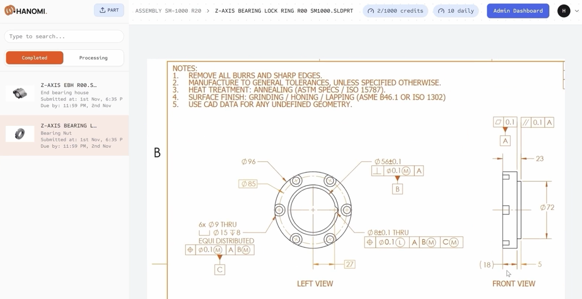
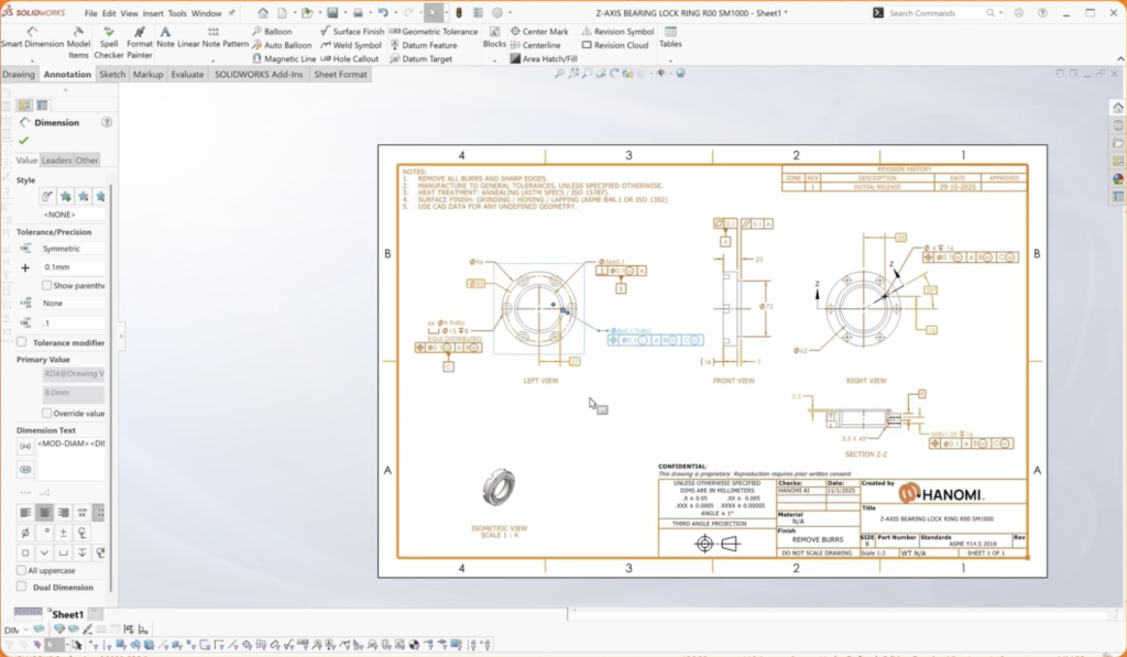
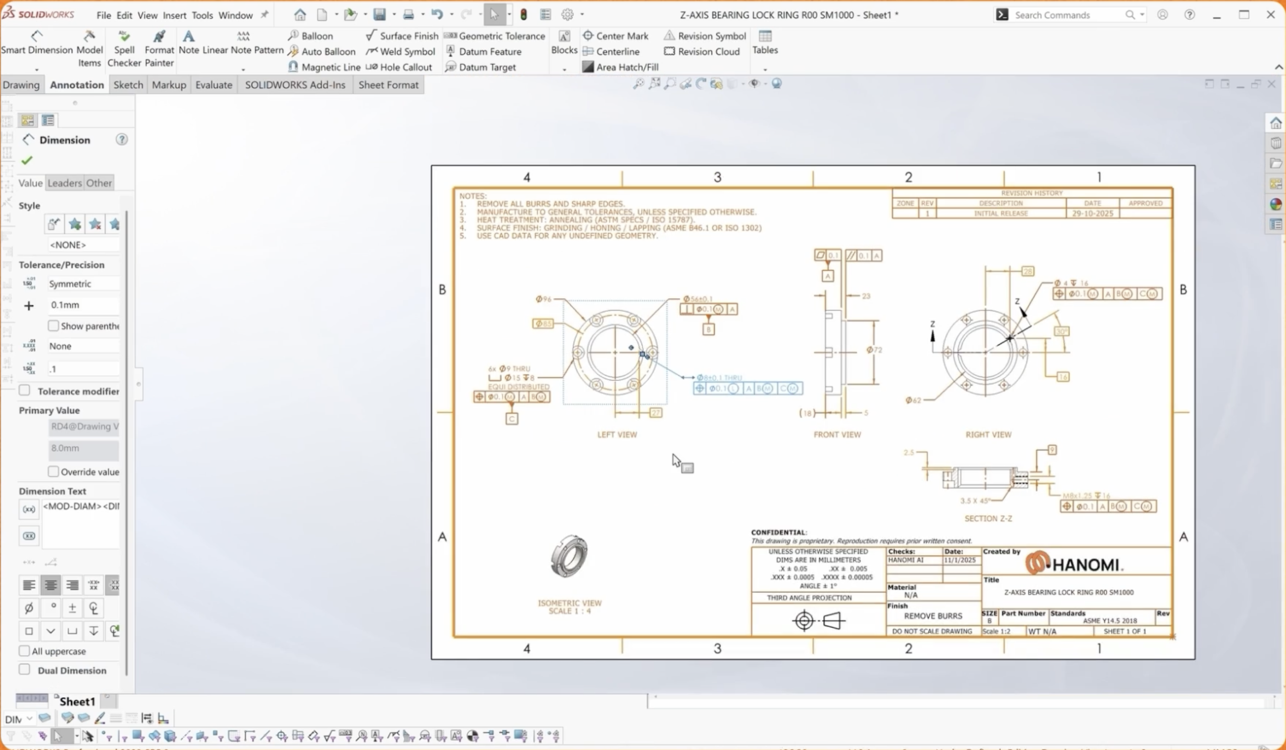
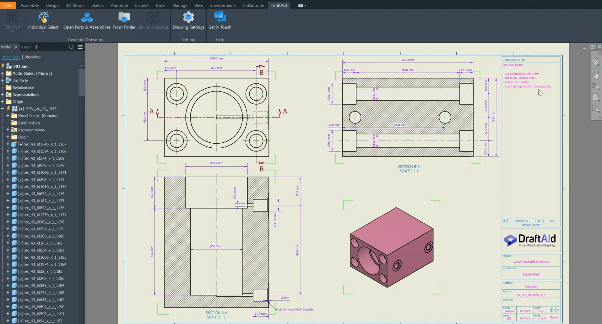
The solution is software that automatically generates your 2D manufacturing drawings straight from the 3D model, with a focus on mostly complex drawings that require GD&T.
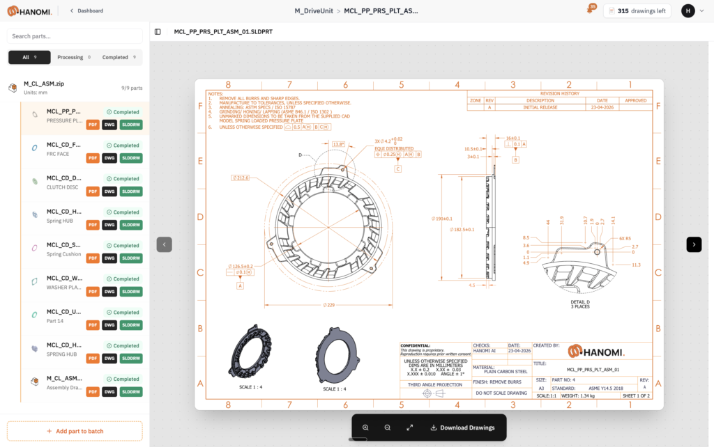
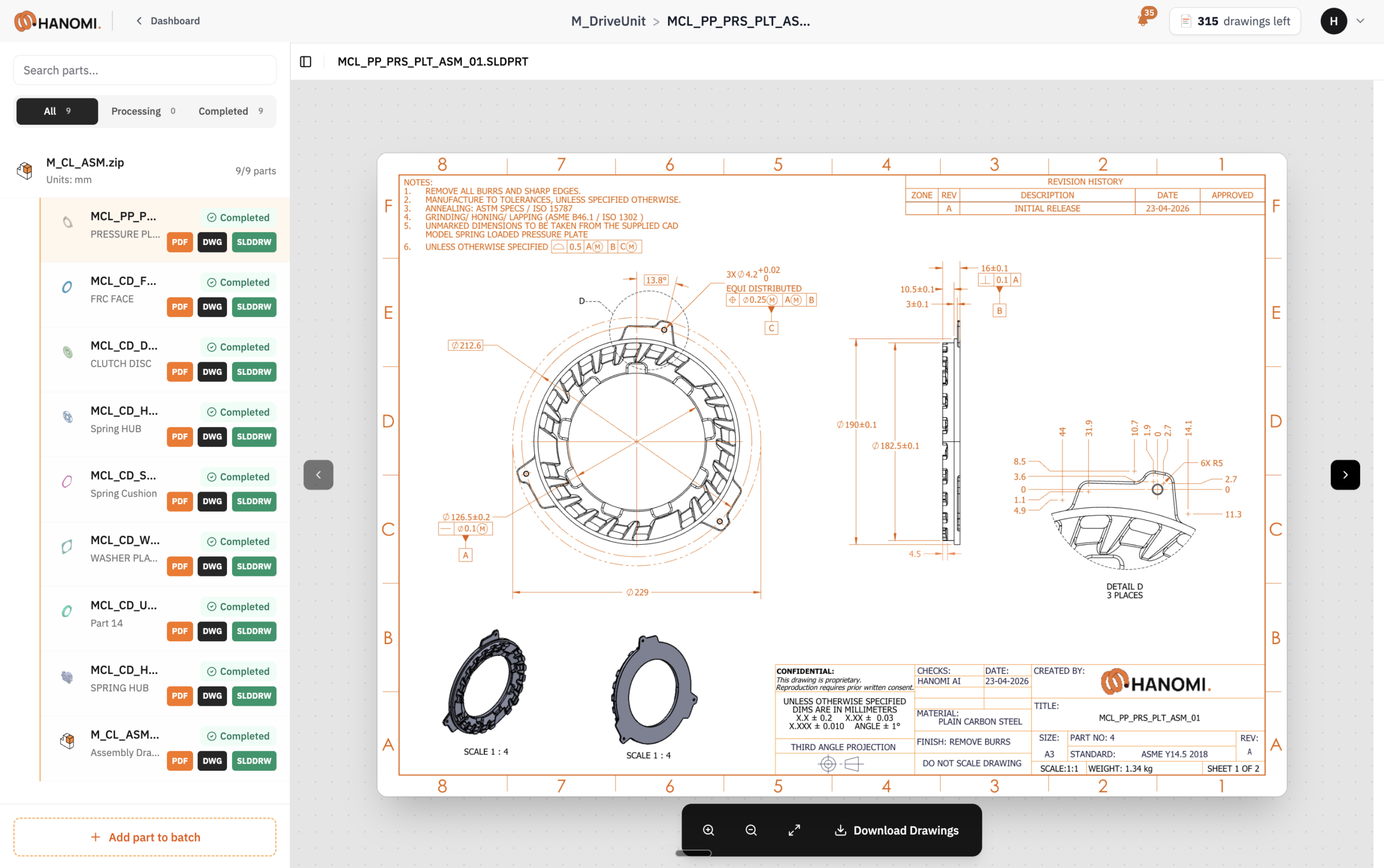
One of the software’s strengths is understanding the client. Two aerospace companies can work on similar parts but have completely different drawing requirements, simply because they deal with different manufacturers or have different machines in the shop. So the first part is understanding the manufacturing side, the constraints your suppliers or your own shop have, and then applying those constraints to the drawing. The result is drawings that are highly customized to each company.
We try to make the output hands-off by the time it is delivered. Worst case, we have seen edits of 10 to 15 minutes on a drawing that would normally take four to five hours, but the goal is for engineers to do just a final QC and review.
What kind of drawing takes four to five hours?
It depends whether you want production or inspection drawings, but we work with cast parts, machined parts and sheet metal, and also welded structures.
Welded structures take a long time, especially heavy machinery, where you have to build up the weldment. Cast parts with post-machining also take a while. Roughly speaking, something in the order of 15 to 20 views, including orthographic views, cross-sections, detail views, etc. takes a significant amount of time. Especially with GD&T.
Is Hanomi also suitable for speeding up making simple sheet metal drawings?
The tool currently gives you two iterations. The first you get in under five minutes, actually two to three, and that nails down all the simple parts, sheet metal or machine flanges. For more complex parts it takes more iterations. You still get a first iteration after five minutes, but treat that as a starting point, not the end point.
The final version of a complex part takes 30 minutes or more. For simple parts our clients do them at scale, so they might take 10 or 15 minutes. And most of our clients still put some GD&T even on sheet metal, nothing fancy, maybe location tolerances on holes they drill on a CNC after bending.
What does the process actually look like?
For complex parts the software needs the assembly. You cannot hand it a random part and expect magic, just like you cannot hand a random part to an engineer and expect a perfect drawing without context.
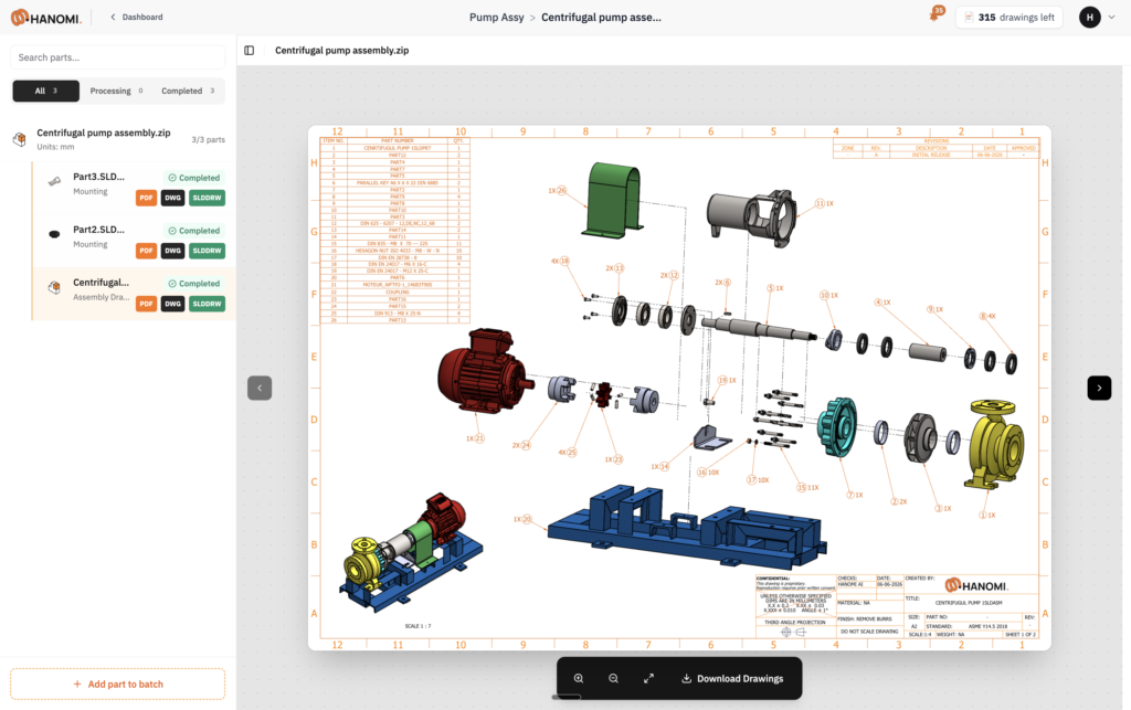
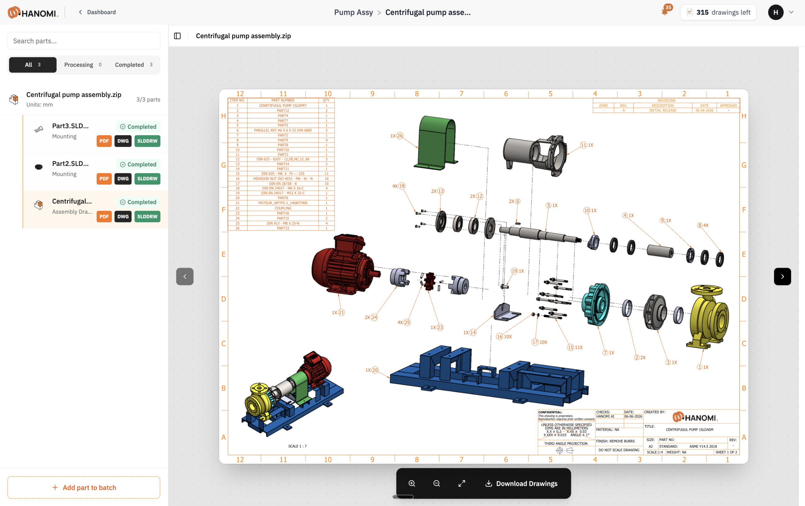
There are two versions of the software, a desktop app and a web platform. In the desktop app you click a few buttons to select your parts. Either way you provide the same information, your manufacturing process, your datums, and the fits you want for different surfaces. Then you submit, the drawing gets processed, and you get back your native file format, so you can download it and open it in your own CAD. If you are happy with the first version after a few minutes you can push it to your PLM or PDM. If not, you wait a bit longer for the more complex result.
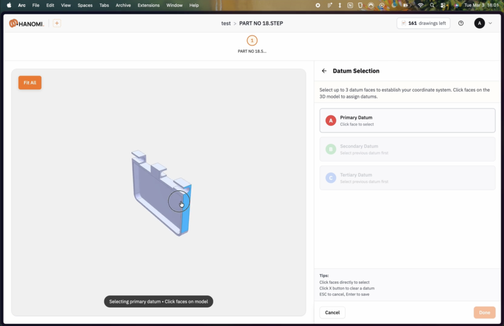
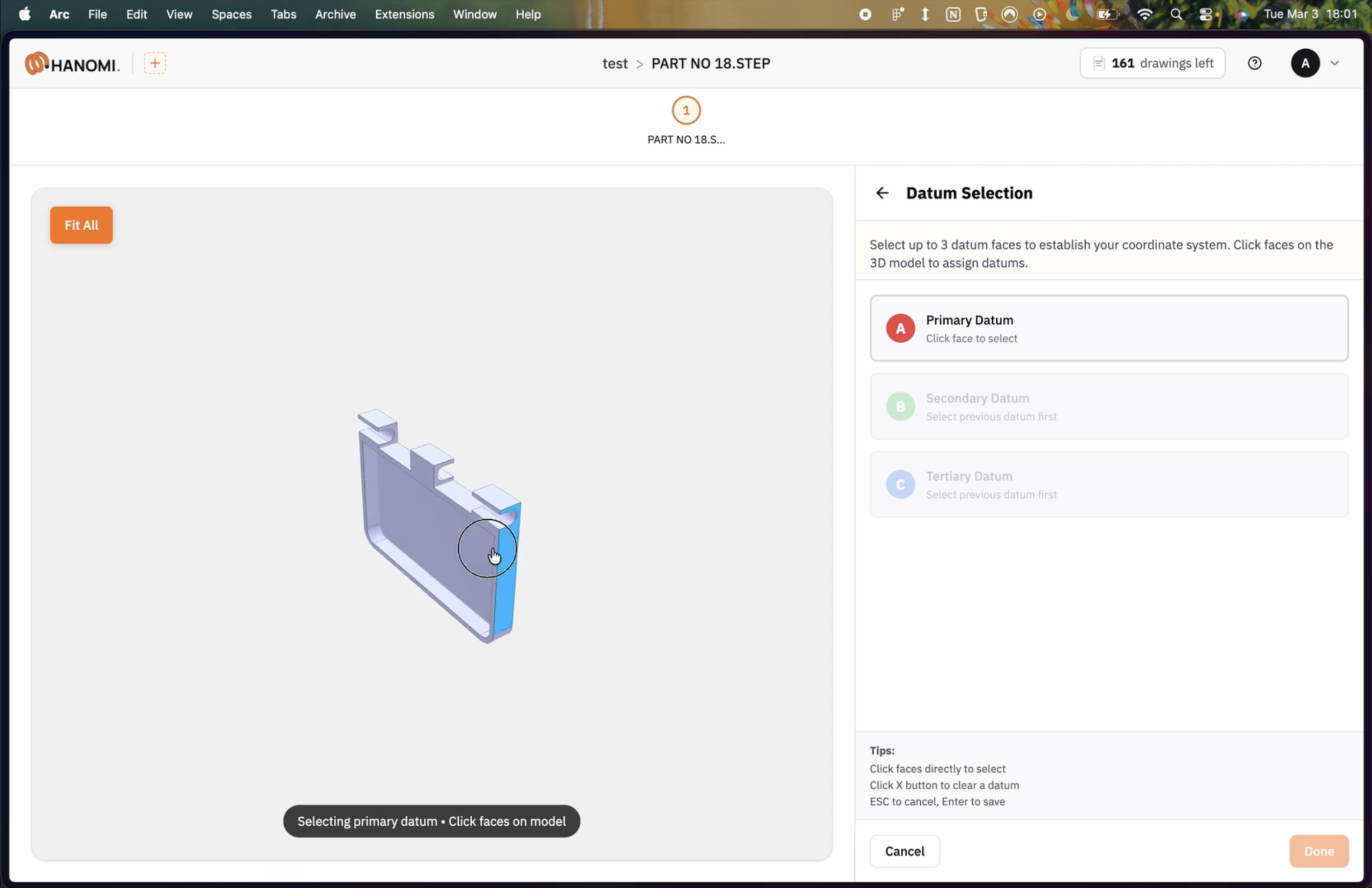
What does it read from the assembly, if I am already assigning the datums myself?
For simple parts like brackets or sheet metal you can skip the datums and let the software pick them automatically, but in about 95% of cases clients select datums anyway, because they want more control or they use those datums for inspection.
The assembly is not just about datums though. At the end of the day everything is about functionality. The whole point of a drawing is to describe the part’s function to someone, the manufacturer, who often receives just the part drawing with no idea what it does. So the assembly tells us the mating faces, the relationships between them, the materials. If a metal surface slides against a plastic one you might want a different roughness on the metal, even if that surface is not a datum. All of that feeds into the drawing.
Will the drawings look like my drawings, the title block, the company style?
Yes, and we have spent a lot of time on this. Manufacturers are often very picky. If they suddenly receive a different style they can freak out and spend more time on the part just because of that, so you have to be consistent with the company’s standards.
The basics are templates, scale and sheet size. Then there are the tolerances. We use ISO 2768-mK in the background, but every company has its own standards. The same goes for GD&T. You might use the latest ASME standard, but if your manufacturer still wants to use concentricity, which has been removed from the latest standard, we can support that too.
We can also change where you dimension from, whether from the datums or from an origin point, because your CNC or your CMM zeroes at a specific point on the part. All of that is handled through customization.
How does the software handle me updating half the parts in a project and the need for revisions?
Revisions come up frequently. We have a threshold in the backend for what counts as a revision. If you just move a hole or change a parametric feature, customers usually do not run it through us, because it updates automatically in the CAD environment and you keep all your references. But if you change more than 30% of the features, it is treated as a new drawing. Below that, you resubmit through the desktop app or platform linked to the same assembly, and we produce a revision where only the changed features are updated.
Could you hand this to a junior and trust the output, or is it really for experienced engineers?
You need experience to define the requirements, that is the main point. But the inputs themselves are not many, so a junior can use it, as long as they are precise about things like datums and fits.
Does it give any recommendations, like fits based on function?
Functionality is exactly what we built it around. If you have a shaft spinning at 100,000 RPM you might want total runout instead of runout, and that is where you would specify it.
Right now it is input in, output out, not interactive. We are releasing something this summer where you can talk to the drawing. It is not for simple edits, it is for things that would take you 15 minutes by hand, like re-dimensioning features or moving them into detail views. You will ask the tool and it does it quickly. It exists in the backend but has not been deployed to the public yet.
For Companies Making 200+ Drawings a Month
What kind of companies is Hanomi for?
Right now mainly enterprise clients in aerospace, automotive and robotics. We always look for a specific use case because we cannot handle everything yet, as much as we would like to. So it is machined parts, custom parts with post-machining, sheet metal, and we have started on simpler injection-moulded parts.
We mostly talk in terms of drawings per month. A good fit is in the order of 200 to 500 drawings per month, with moderate levels of complexity.
The challenge is that clients see that it works, get excited and start throwing random things at it. One client got confident and pushed a 22-page drawing through, then asked if we would support it. We are not there yet. Our sweet spot is any drawing within those processes and within a reasonable level of complexity, about 15 to 20 views.
This sounds like it is for high-precision, well-funded companies. Is there anything here for an SME?
Honestly, for small and medium businesses the value is more in the software’s expertise than in time or cost savings. If you make one product a year you might need 20 to 100 drawings, half of them revisions, so the time and cost savings are limited. What we have done is generate our own data in house, by running an internal setup that behaves the way a small business would. That gave us early exposure to the problems those companies face, and it showed us extensions of the product that could deliver them more value down the line.
So an SME can still use it. They will just get limited value from what the product is today, perhaps needing it for a couple of months a year.
What is the biggest benefit your clients point to?
Standardization, which we did not over-index on at first. Having everything standardized and compliant with their requirements turns out to be hugely valuable, both for QC and on the manufacturing supply side. And then of course the cost reduction.
Any customer stories that stand out?
One large OEM client, where the head of engineering had not made drawings in a long time, told us his teammates now make fun of him because “Hanomi makes better drawings than you.” That was pleasing to hear.
In another case we automated a workflow where a large client used to spend three days of working time on a specific subset of sub-assemblies. With our tool it took a few hours. That gave us a lot of visibility, because the client recommended us to others.
Integration with Major CADs
What is the level of integration with CAD and PLM systems?
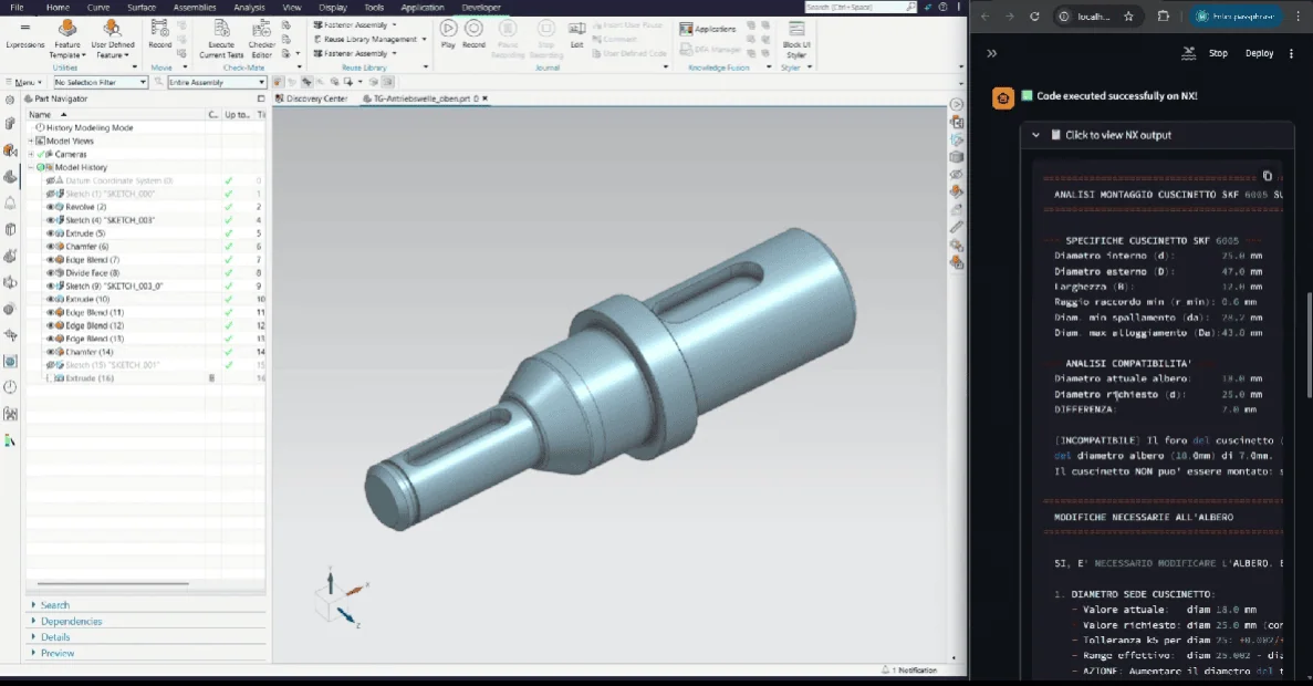
We are integrated with the major CAD software, mainly Solidworks and NX, which is what our clients use, so the output is native and stays linked to the 3D model. PLM is more case by case. By default, if the output is linked to the CAD file the PLM reads it automatically. Sometimes we have had to tweak title blocks so the PLM reads them cleanly. If a client wants deeper integration we handle it case by case, because even with the same PLM system companies build their own things on top.
What do you have in place for IP protection?
We can deploy to your own network, and we use standard ways of encrypting and sending data. We never retain 3D data. You need it on the platform to select datums and so on, but once you submit the drawing the 3D input is never retained.
On top of that, we can customize to your organization without training on your data at all. Even without training we can still customize, because the architecture is not a black box. It is a mix of probabilistic and deterministic layers with an agentic orchestrator, if you want to call it that. We tweak parameters so there is no training on your data but we still match your way of dimensioning, your GD&T and so on.
What is the cost?
We work on tiers. Pricing depends on parameters like the complexity of the parts, whether you also want assembly drawings, and how many drawings you make per month or year.
Giving Engineers Extra Limbs
What is the vision?
We want to be an infrastructure layer, a single source of truth across stakeholders and value chains. Right now that source of truth is the drawing, but it can also be model-based definition. In fact MBD generation is an intermediate step in our process. We do not generate drawings directly, we first go to a layer of abstraction and then place it on the drawing sheet. From there we can automate processes on top.
We are starting with 2D drawings, but we want to move further back in the value chain and help with the design itself. First the drawing, then DFM and DFA feedback, and then automating part of the 3D design, all while keeping that single source of truth about how the part will be manufactured and what actually matters when you ship it, whether that is interferences, GD&T or something else.
3D printing and injection moulding open up very different optimizations, merging parts and removing assembly steps. How does that fit?
I have used parts of the software for my own work. I have been making joints for robotic-arm actuators for a long time. Even with 3D printing, take a resin printer. You might think you just press a button and print, but that is not the case if you need very tight form or shape tolerances. A resin printer is notoriously known for deforming things, even slightly, and when a part is very precise that matters.
So that is an immediate place we can give fast DFM feedback, helping hobbyists or companies at the prototype stage understand how to print a part, what support angle to use, so that a toleranced surface does not get deformed by the printing process. It is relatively simple, and a good use case to test with.
Where does the name Hanomi come from?
I am a big fan of One Piece. In it you eat devil fruits that give you superpowers, and there is one called the Hana Hana no Mi that gives you extra limbs. We took that and made it into Hanomi.
The drawings are the starting point. We want to give engineers superpowers, extra limbs. The 2D drawing is not the vision, it is the fastest way to start towards it. There is far more to it, but I would rather go one step at a time.
What is interesting in AI for mechanical engineering besides Hanomi?
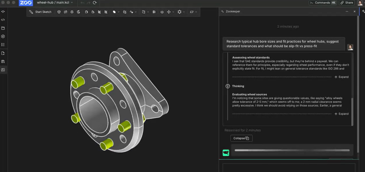
I have been surprised by how fast Claude works with CAD files. When I want to 3D print something, I describe my requirements and specifications very precisely, and without any CAD software or MCP, just using OCC in the background and some scripts, Claude generates the 3D file for me as a STEP file for simple parts. It is fascinating how quickly that has evolved.
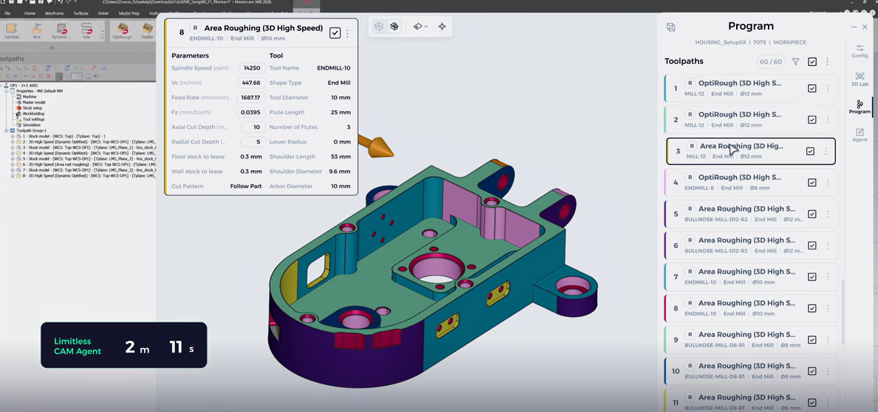
Another company I find interesting is Limitless Labs. I spoke with them a while back and was curious about their very custom approach to generating toolpaths and G code. I am convinced that the use cases at the intersection of engineering and manufacturing, where you need a lot of hard-to-capture data, are exactly where the big incumbents and general LLMs struggle.
Related Topics
 Uliana Krayneva
 4
4
 Efe Erdem Akın
1
Efe Erdem Akın
1



Comment(0)