 Europe
  Türkiye
  United Kingdom
  Global


 0
0

First, let’s establish some fundamental definitions.
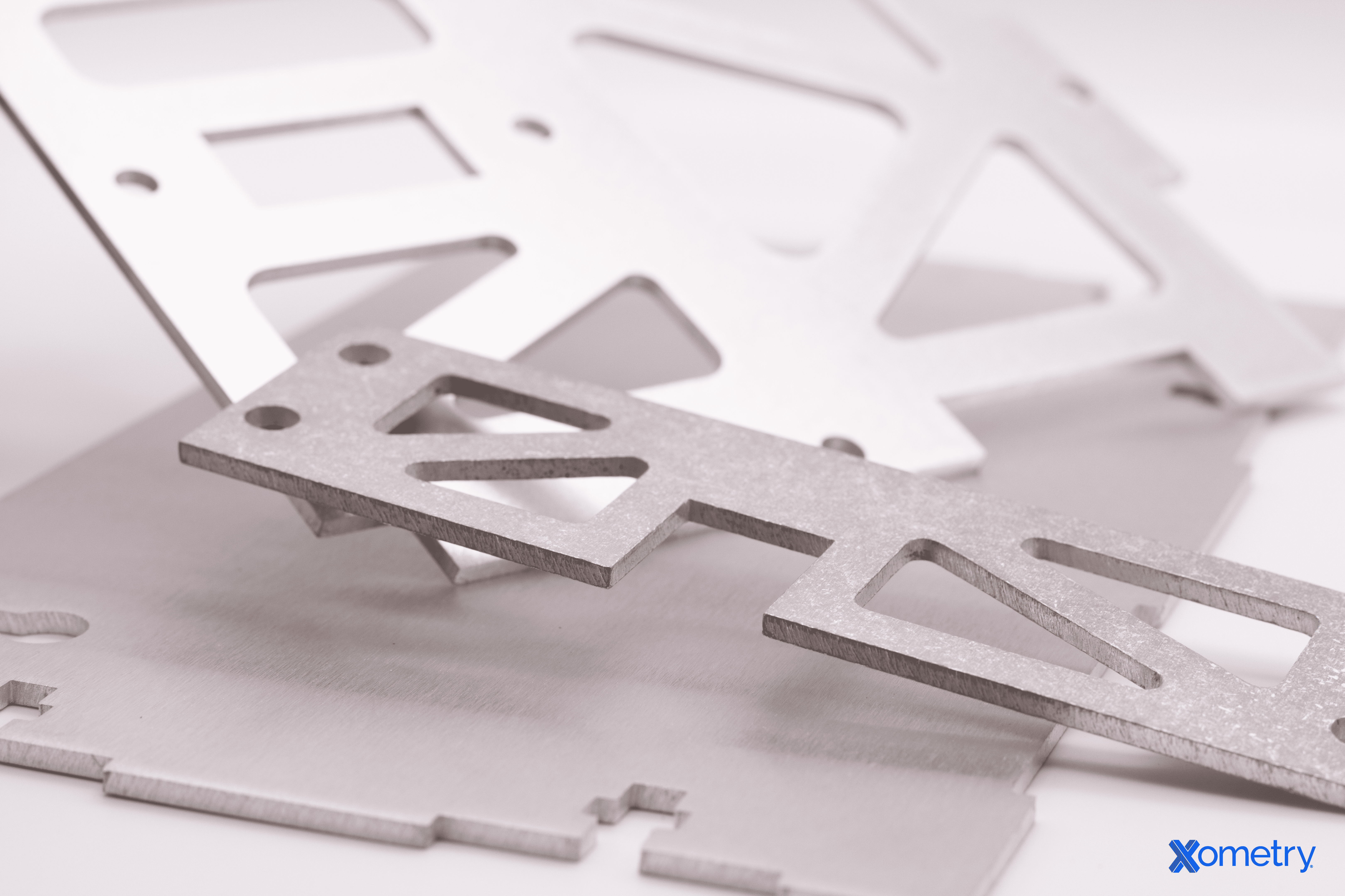
What Is Sheet Metal?
Sheet metal is a flat, thin-rolled piece of metal with a uniform thickness, typically ranging from 0.5 to 6 mm. And that’s the important part. Anything below is generally foil (as in aluminum foil), while anything thicker is considered a plate. Note that some sources cite slightly different numbers.
While this article focuses on sheet metal processes, we will also cover some methods commonly applied to thicker plates due to the flexible nature of the term “sheet metal fabrication” itself.
Understanding Gauge vs. Millimeters
Beyond the metric system, material thicknesses are commonly measured in inches or using gauge numbers in the American system. Gauge numbers, however, can be confusing because the same gauge number corresponds to different actual thicknesses depending on the material.
Always specify sheet thickness in millimeters (mm) or inches, not gauge. For example, a “10 gauge” aluminum sheet is around 2.6 mm, while a “10 gauge” steel sheet is about 3.4 mm. Specifying precise units avoids confusion and potential errors in fabrication.
To convert gauges, refer to a reliable sheet metal gauge chart.
The reason why sheet metal fabrication plays such a big role in the industry is because of its versatility and cost. For one, sheet metal can be cut, bent, stretched, drawn, joined and finished into everything from an automotive body panel to the simplest flat side sheet of a conveyor. Secondly, there are a lot of material properties on offer, some inherent to the material itself (steel vs copper vs aluminum, etc.) and some stemming from heat treatment.
Raw Materials: Sheets vs. Coils
Sheet metal is primarily supplied in two main forms: coils and sheets. Coils are predominantly used in high-speed, continuous manufacturing processes such as stamping and roll forming, which require the material to be processed as a long, uninterrupted strip. Sheets, on the other hand, are preferred for most other sheet metal fabrication processes, including individual or small-batch cutting, bending, and punching operations.
Sheets typically come in standard sizes, with 1500 x 3000 mm being one of the most common sizes. Considering these standard dimensions during the design phase is crucial for optimizing material utilization and effectively managing costs.
Failing to account for standard sheet metal sizes during the design phase can significantly increase your project’s costs. Poor planning might lead to excessive material scrap, overpaying for hard-to-find custom sizes, or the need for unnecessary welding processes later on.
Sheet Metal Cutting Processes
Once the material is selected, the first fabrication step is almost always cutting. The choice of cutting method is a critical decision based on several key factors:
- Material compatibility
- Material thickness
- Required speed and production volume
- Desired quality and edge finish
- Tolerance requirements
- Part geometry
- Cost per part
Laser Cutting
Laser cutting is a thermal cutting process that uses a focused laser beam to melt material with exceptional precision and speed. It is one of the most common sheet metal cutting methods due to its versatility, accuracy, cost-effectiveness, and suitability for a wide range of materials.
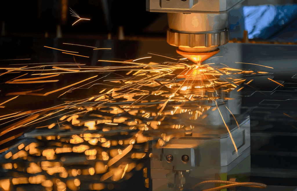

How It Works
A laser cutting machine generates a high-intensity beam of light, which is focused onto a small spot (often around 0.2 mm in diameter). This concentrated energy melts the material, and a high-pressure assist gas (such as oxygen, nitrogen, or compressed air) blows the molten material out of the cut (kerf). This gas jet prevents the material from re-solidifying and ensures a clean edge.
There are three primary types of laser systems:
CO2 Lasers
CO2 lasers are the most established technology, operating at a 10.6-micrometer wavelength. They are highly versatile and can cut non-metals like wood and plastics, but they are also powerful metal cutters, capable of processing steel up to 30 mm.
However, they are less effective on reflective metals; thickness limits for aluminum and brass are typically around 10 mm, and copper is limited to 4-5 mm. CO2 systems also require regular maintenance (e.g., for mirrors and resonator tubes) and consume more electricity than newer technologies.
Fiber Lasers
Fiber lasers are a solid-state technology operating at a 1.07-micrometer wavelength. This wavelength is much better absorbed by reflective metals like aluminum, copper, and brass, making fiber lasers highly effective for these materials.
They are 2-3 times faster than CO2 lasers on thinner sheet metal and are significantly more energy-efficient. With no mirrors to align, they require minimal maintenance. Their primary limitation is a lower maximum thickness on steel (typically 20-25 mm) compared to high-powered CO2 lasers.
Nd:YAG Lasers
Nd:YAG lasers, another solid-state type, offer excellent beam quality and pulse control, making them ideal for high-precision applications or cutting foil. However, their power output is generally lower than CO2 or fiber, and they often have high operating and maintenance (due to lamp or diode failure) costs, limiting their use to specific, niche assignments.
Advantages and Limitations of Laser Cutting
| Advantages | Limitations |
| High Precision: Achieves tight positioning accuracy, often ±0.1 mm. | Heat-Affected Zone (HAZ): Alters material properties locally, though the zone is narrow (0.1–0.5 mm). |
| Excellent Edge Quality: Produces clean, sharp edges with minimal dross, reducing post-processing needs. | Thickness Limits: Less effective on very thick plates (e.g., >25-30 mm) compared to other thermal methods. |
| High Cutting Speed: Very fast, particularly on thin to medium-thickness materials. | Reflective Material Issues: Highly reflective metals (e.g., copper, brass) can be challenging, especially for CO2 lasers. |
| Low Distortion: The small HAZ and high speed allow for tight nesting of parts, maximizing material utilization. | Warping Risk: Can cause warping on very thin sheets (<1 mm) if heat input is not carefully controlled. |
| Versatility: Cuts a wide range of materials, including non-metals like plastics and wood (with CO2 lasers). | Fumes & Ventilation: Produces hazardous fumes that require robust ventilation and filtering systems. |
Material Applications and Considerations
The ideal range for metal cutting is typically between 0.5 mm and 25 mm. While high-power industrial lasers can cut thicker plates, the cutting speed decreases and the kerf quality deteriorates.
Thin sheets (below 1 mm) require precise parameter control to avoid warping from heat distortion. Overall, laser cutting is ideal for parts requiring complex shapes, high precision, and a clean edge finish that needs minimal post-processing.
Industry Applications
Laser cutting is used across nearly every industry. Common applications include:
- Automotive: Precision brackets, exhaust components, and prototype parts.
- Aerospace: Lightweight structural components and engine parts requiring high precision.
- Electronics: Enclosures, chassis, heat sinks, and EMI shielding.
- Construction: Decorative panels, HVAC components, and custom metalwork.
Plasma Cutting
Plasma cutting is a thermal cutting process widely used in heavy manufacturing and construction. While less precise than laser cutting, it excels at quickly cutting thick, electrically conductive metals.
How It Works
Plasma cutting uses a high-velocity jet of ionized gas (plasma) to melt and expel material from the cut. The process starts by passing an electric arc through a compressed gas (like nitrogen, argon, or air), which ionizes the gas and heats it to extreme temperatures—often exceeding 20,000°C .
The cutting torch’s electrode and nozzle create the arc. Because the resulting plasma is electrically conductive, it sustains the arc between the torch and the metal workpiece. This operating principle means plasma cutting is limited to electrically conductive materials. With appropriate systems, it can cut thicknesses up to 100+ mm.
Modern systems use a “pilot arc” (a small plasma spark) to initiate the main cutting arc upon contact with the workpiece .
Advantages and Limitations of Plasma Cutting
| Advantages | Limitations |
| Fast Cutting Speeds: Very fast, especially on thick materials]. | Wider Kerf: The cut path is wider than a laser’s, resulting in lower precision. |
| Thick Material Capability: Cuts steel up to 100+ mm; less for stainless steel and aluminum. | Larger HAZ: The heat-affected zone is larger than a laser’s, altering more of the base material. |
| Cost-Effective on Plate: Often cheaper than laser cutting for plates thicker than 10 mm. | Edge Quality: Can produce dross and a slight edge bevel (angularity), often requiring post-processing. |
| Conductive Materials: Cuts all electrically conductive metals, including reflective metals that challenge lasers. | Conductive Only: Cannot cut non-conductive materials like wood or plastics. |
| Portability: Smaller, portable units are available for on-site fieldwork. | Fumes & Ventilation: Produces significant hazardous fumes and arc light, requiring ventilation. |
Material Applications and Considerations
Plasma cutting is compatible with all electrically conductive metals. Carbon steel cuts well using compressed air or oxygen. Stainless steel and aluminum achieve better results (minimized oxidation and better edge quality) using nitrogen or argon/hydrogen gas mixtures.
While laser cutting is increasingly competitive up to 25-30 mm, plasma cutting’s true “sweet spot” is in the 10 mm to 50 mm thickness range.
On thin sheets, the high heat input can cause significant warping. On materials thicker than 50 mm, the cut edge often shows a noticeable bevel (angularity) and roughnessThis is why it’s a popular choice for structural applications where function and strength are prioritized over fine aesthetics.
Industry Applications
Plasma cutting is a go-to process for heavy-duty applications:
- Heavy Construction: Structural steel fabrication, plate cutting.
- Shipbuilding: Hull plates, structural components.
- Industrial Equipment: Pressure vessels, storage tanks.
- Automotive: Heavy truck parts, chassis components.
- General Fabrication: Brackets, frames, and other thick plate components.
Flame Cutting
Flame cutting, also known as oxy-fuel cutting, is a thermal process primarily used for cutting very thick carbon steel plates. While not a common first choice for thin sheet metal, it’s an economical and portable method, especially for on-site work or in shops equipped for heavy steel fabrication.
How It Works
Oxy-fuel cutting and flame cutting are interchangeable terms, both comprehensively describing the process. Oxy-fuel cutting uses a high-temperature flame from a fuel gas (like acetylene, propane, or natural gas) to heat mild steel to its ignition temperature, which is around 900°C.
Once this temperature is reached, a separate, high-pressure jet of pure oxygen is directed at the spot. This triggers a rapid oxidation reaction (effectively, a controlled, high-speed rusting or burning) that severs the material. The pre-heat flame and the oxygen jet work in tandem to move along the cut path.
This process is limited to carbon and low-alloy steels. It works best on mild steel (below 0.25% carbon), as higher carbon content (over 0.6%) interferes with the process and requires pre-heating. It is not suitable for stainless steel, aluminum, or other non-ferrous metals. Elements like chromium or nickel form a protective oxide layer that resists the oxidation reaction, preventing the cut.
Advantages and Limitations of Flame Cutting
| Advantages | Limitations |
| Unmatched Thickness: Excels at cutting very thick plates, from its ideal range of 10–150 mm up to 300 mm or more. | Carbon Steel Only: Cannot cut stainless steel, aluminum, or other non-ferrous metals. |
| Low Equipment Cost: Torch and gas-handling equipment are relatively inexpensive. | Wide Kerf: Produces a very wide cut (3 mm+), resulting in low precision and material loss. |
| Portability: Portable, manually-operated units are common, making it perfect for on-site fieldwork. | Large HAZ: Creates a very large heat-affected zone (HAZ), significantly altering the material’s properties near the cut. |
| No Electricity Required: Operates on fuel gases and oxygen only, making it useful in locations without power. | Poor Edge Quality: Leaves a rough, tapered edge with significant dross, requiring heavy post-processing. |
| Versatile Tool: The same torch setup can often be adapted for welding or pre-heating applications. | Slow Cutting Speed: Significantly slower than plasma cutting on comparable material thicknesses. |
Material Applications and Considerations
Flame cutting is most effective on mild steel with a low carbon content (below 0.25%). While higher carbon steels can be cut, they require careful pre-heating and controlled cooling to prevent cracking and embrittlement.
The main advantage of this process is for materials thicker than 25 mm, where other methods become less economical or slower. The cut quality is comparatively poor and is not suitable for precision components or thin-gauge sheet metal.
Industry Applications
Given its capability with thick, heavy plate, flame cutting is used almost exclusively in heavy-duty industries:
- Construction: Cutting structural steel beams and heavy plates.
- Heavy Equipment: Fabricating chassis components and thick brackets.
- Demolition and Scrapping: Segmenting large metal structures for removal.
- Bridge Construction: On-site cutting and fitting of structural steel.
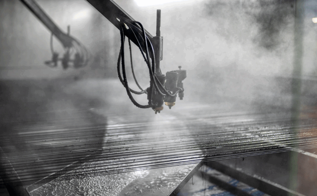
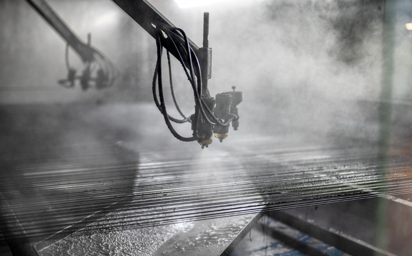
Waterjet Cutting
Waterjet cutting is a mechanical erosion process that cuts material using a high-velocity stream of water. Unlike thermal methods (laser, plasma), it does not generate a heat-affected zone (HAZ). This, combined with its ability to cut almost any material, makes it an essential process for specialized applications.
How It Works
Waterjet systems operate in two ways: pure water and abrasive.
- Pure waterjet uses a stream of water pressurized to 210–620 MPa (30,000–90,000 psi), focused through a tiny orifice (around 0.2 mm) to cut soft materials like foam and rubber.
- Abrasive waterjet, the method used for sheet metal fabrication, introduces an abrasive (most commonly garnet) into the high-pressure water stream. This mixture of water and abrasive particles erodes the material through high-speed impact.
This is a mechanical cutting method, involving no melting or chemical reactions. The cutting head, controlled by G code, bombards the material, eating away at it to create a precise cut with no thermal distortion.
Advantages and Limitations of Waterjet Cutting
| Advantages | Limitations |
| No Heat-Affected Zone (HAZ): The cold-cutting process does not distort or alter material properties. | Slow Cutting Speeds: Significantly slower than laser or plasma, especially on thick materials. |
| Cuts Any Material: Can cut virtually anything, including metals, composites, ceramics, stone, and glass. | High Operating Cost: High costs due to abrasive consumption and high-pressure pump maintenance. |
| Excellent Edge Quality: Produces a smooth, satin-like edge finish that often requires no post-processing. | Taper Risk: Can produce a slight edge taper (kerf angle) on very thick materials, though modern 5-axis heads can compensate for this. |
| Thick Material Capability: Can cut metals up to 250 mm thick. | Noise: The process is exceptionally loud. |
| High Precision: Achieves high accuracy, with tolerances depending on cutting speed. |
Material Applications and Considerations
Waterjet cutting is the ideal solution for materials that are difficult or impossible to cut with thermal processes. This includes tool steels, titanium, exotic alloys, and composites.
Waterjet is the go-to process for heat-sensitive materials (like heat-treated parts or alloys where you must preserve temper) and for designs where no thermal distortion or change in material properties (HAZ) is acceptable.
The cut quality is exceptional, particularly when using slower cutting speeds, which also produces excellent edge perpendicularity (minimal taper).
Industry Applications
- Aerospace: Cutting titanium components, composite parts, and high-precision brackets.
- Medical Devices: Manufacturing surgical instruments, implants, and precision components.
- Tool and Die: Cutting hardened tool steels and intricate tooling components.
- General Fabrication: Low-volume, high-precision parts made from diverse or difficult-to-cut materials.
Having discussed the four primary cutting methods, let’s wrap it up by comparing them directly:
Sheet Metal Cutting: Process Comparison
| Parameter | Laser Cutting | Plasma Cutting | Flame Cutting | Waterjet Cutting |
| Process Type | Thermal (melting) | Thermal (plasma arc) | Thermal (oxidation) | Mechanical (erosion) |
| Precision | ±0.1 mm | ±0.2 mm | ±1-3 mm | ±0.05–0.1 mm |
| Max Steel | 25-30 mm | 100+ mm | 300+ mm | 250+ mm |
| Max Aluminum | 20-25 mm | 100+ mm | Cannot cut | 250+ mm |
| Max St. Steel | 15-20 mm | 50-80 mm | Cannot cut | 200+ mm |
| Heat Affected Zone | 0.1-0.5 mm | 1-3 mm | 3-8 mm | None |
| Kerf Width | 0.1-0.5 mm | 1-8 mm | 3-10 mm | 0.8-1.5 mm |
| Cutting Speed | Fast (thin) | Very Fast (thick) | Slow | Very Slow |
| Edge Quality | Excellent | Fair to good | Poor | Excellent |
| Material | Most metals, some non-metals | Conductive only | Carbon steel only | All materials |
| Operating Cost | Medium to High | Low to Medium | Very Low | Very High |
| Equipment Cost | High | Medium | Very Low | Very High |
| Best For | Complex shapes, precision | Thick structural steel | Very thick carbon steel | High precision, no thermal input |
Shearing
Shearing is a mechanical cutting process that uses two opposing blades to cut sheet metal along a straight line. It is often the most economical method for making straight cuts due to its simplicity and high speed.
How It Works
The shearing process is analogous to using a pair of scissors. The machine uses two blades, an upper and a lower, positioned with a slight angle (1–2 degrees) between them. This angle, or “rake,” means the cut happens progressively along the material’s length rather than all at once, which significantly reduces the force required.
A clamping mechanism holds the sheet metal in place, and a back gauge is used to set the dimension for accurate, repetitive cuts. Most modern shears are hydraulic, providing smooth motion and high power to cut thick materials (e.g., carbon steel up to 25 mm).
Parallel blade shears, though less common, are ideal for thin sheets and small cuts, producing burr-free edges, unlike angled blades that can deform soft materials.
Mechanical shears, though less popular, are still found in workshops, good for thin sheets and easier to maintain, but with limited force at lower outputs.
Advantages and Limitations of Shearing
| Advantages | Limitations |
| High Speed: Very fast, as it can sever a long edge in a single stroke. | Straight Cuts Only: Cannot be used to cut curves or complex geometry. |
| Low Operating Cost: Fast cycle times and minimal consumables (no gas, abrasives). | Edge Quality Varies: Can leave a burr or slight deformation, especially with improper setup. |
| No HAZ: As a mechanical process, it produces no heat-affected zone (HAZ) or thermal distortion. | Blade Wear: Blades dull over time and must be maintained, affecting cut quality. |
| Simplicity: A simple, reliable process that does not require highly skilled operators. | Ductile Materials: Works best on ductile materials; hard or brittle metals may fracture poorly. |
| High Production: Ideal for high-volume blanking operations and preparing stock. |
Material Applications and Considerations
Shearing works best with ductile materials like mild steel, medium-carbon steel, stainless steel, and aluminum. Harder materials require more force and accelerate blade wear.
The cut edge will typically have a small burr on the bottom. The quality of the cut is highly dependent on the “blade clearance,” or the gap between the two blades.
Blade clearance is key cut quality in shearing is highly dependent on blade clearance, the gap between the upper and lower blades. This is typically set to 5-10% of the material thickness. Too little clearance causes rapid blade wear, while too much clearance can cause the material to bend or twist, resulting in a large burr.
Industry Applications
Shearing is a foundational process used for preparing material blanks:
- Stock Material Suppliers: Cutting large sheets or plates into smaller, sellable sizes.
- HVAC: Preparing straight sections of galvanized steel for ductwork.
- Roofing: Cutting metal roofing and siding panels.
- General Fabrication: Blanking simple parts for subsequent bending or punching.
- Appliance Manufacturing: Creating flat blanks for deep drawing processes.
Blanking and Punching
Blanking and punching are high-speed, mechanical cutting processes ideal for high-volume production. By using a dedicated tool and die set, they achieve very fast cycle times, consistent quality, and high dimensional repeatability.
How It Works
The core mechanism for both processes involves a punch (upper die) that forces the sheet material through a die opening (lower die). The primary difference between them is the intent—i.e., whether the cutout or the remaining sheet is the final product.
- Blanking: The piece that is punched out is the desired product. The surrounding material, or “web,” is the scrap. This is used to create parts like washers, gaskets, and gear blanks.
- Punching: The piece that is punched out is the scrap. The main sheet, which now has holes or slots, is the desired product. This is used to create ventilation holes in electronics enclosures or mounting holes in brackets.
- Fine Blanking: This is a high-precision variation of blanking that uses extremely tight clearances (up to 10x less than standard) and controlled pressure. It produces parts with very smooth, square edges, and is often used for surgical instruments or watch components.
- Perforating: This is a form of punching that uses a multi-punch tool to create many holes, often in a set pattern, with a single press stroke.
Advantages and Limitations of Blanking and Punching
| Advantages | Limitations |
| High Speed: Extremely fast cycle times, with some presses reaching 1,000 strokes per minute[cite: 262]. | High Tooling Cost: Dedicated tooling (punch and die sets) is expensive, especially for custom shapes[cite: 269]. |
| Excellent Repeatability: Ideal for high-volume production, as the tool ensures every part is identical[cite: 263]. | Material Thickness Limit: Best suited for sheet metal, typically 6 mm or less[cite: 270]. |
| Low Part Cost (at Volume): Once tooling is made, the cost per part is very low[cite: 266]. | Tool Wear: Tools wear down and require regular monitoring and maintenance to maintain edge quality[cite: 271]. |
| Good Edge Quality: A proper setup with correct clearance produces clean, sharp edges[cite: 264]. | Part Distortion: Can cause part distortion, especially when punching many holes close together[cite: 272]. |
| Flexibility (Turret): CNC turret punches offer flexibility by using a library of standard tools. |
Material Applications and Considerations
- Punching and blanking work best with ductile materials that are less prone to cracking under force. Carbon steel is commonly used up to 6 mm, while stainless steel (which requires more force due to work hardening) is typically limited to 3-4 mm. Aluminum alloys are also a good fit due to their softness, though they can sometimes stick to the punch.
- The edge quality depends on the material’s properties. Ductile materials produce a smoother sheared edge, while harder materials may show a larger fracture zone with a rougher finish.
To prevent material deformation and ensure part quality, follow these design rules:
- Hole Size: The minimum hole diameter should be at least equal to the material thickness, but preferably larger.
- Hole Spacing: The distance between holes should be at least 1.5x the material thickness.
- Edge Distance: The distance from a hole to the part’s edge should be at least 2.5x the material thickness to prevent the material from bulging or deforming.
Industry Applications
- Electronics: Chassis ventilation holes, connector housings, EMI shielding perforations.
- Automotive: Body panel mounting holes, electrical contacts, and precision gears (via fine blanking).
- Appliances: Control panel openings, ventilation grilles, mounting brackets, and decorative perforations.
- HVAC: Ductwork connections, filter housings, and airflow control components.
Sheet Metal Forming Processes
Once a flat sheet metal blank is cut, the next step is often forming. This is any process that shapes the metal by applying force that exceeds its yield strength, causing it to take a permanent new shape.

Springback and Compensation
A critical concept in all metal forming is springback. This is the material’s elastic recovery, or its tendency to “spring back” toward its original flat shape after the forming force is removed.
This happens because a bend creates two zones: the outer layers are stretched (tensile forces), and the inner layers are compressed. Most materials are more resistant to compression than tension, so the compressed inner layers push the material back slightly once the tool is retracted. This is especially common in air bending.
To achieve a precise final angle (e.g., 90°), several compensation methods are used:
- Overbending: The part is bent beyond the desired angle (e.g., to 88°) so that it springs back to the target 90°.
- Bottoming or Coining: A much higher force is used to press the material into the die, which plastically deforms the material and minimizes its ability to spring back.
- Punch/Die Selection: Using punches with a smaller radius can also help “set” the bend and reduce springback.
Springback means that achieving the final angle is highly dependent on material properties, thickness, and the bend radius. Designers must also consider the bending sequence, as some flanges can block the press brake tooling, making subsequent bends impossible.
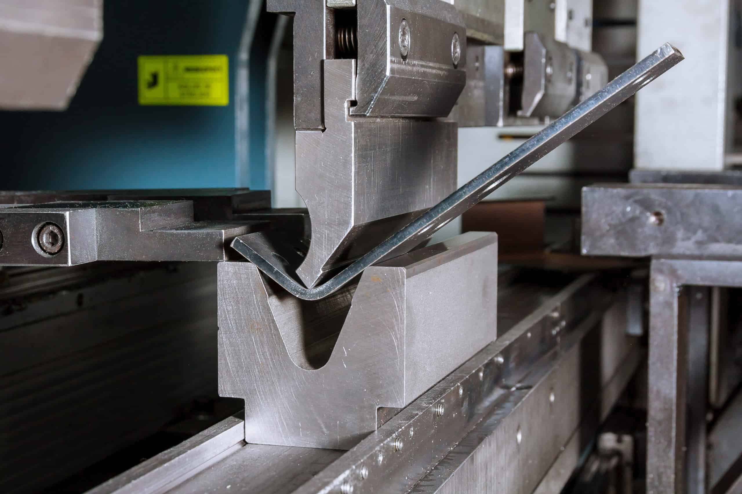
Bending (Press Brake)
When engineers talk about bending, they are almost always referring to press brake bending. It is the most common sheet metal fabrication process used to form the material, capable of producing anything from simple 90-degree bends to complex multi-bend geometries.
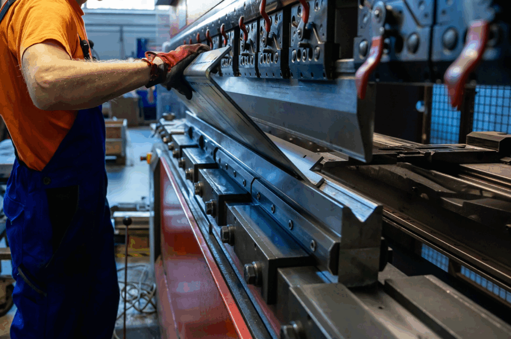

How It Works
A press brake uses a punch (the upper tool) to force a sheet of metal into a V-shaped die (the lower tool). There are three primary methods:
- Air Bending: This is the most common and flexible method. The punch presses the material into the V-die, but not all the way to the bottom. The final angle is determined by the depth of the punch’s stroke, allowing a single toolset to create various angles (e.g., from 90° to 135°). This method requires compensation for springback.
- Bottoming: The punch presses the material so it makes full contact with the die walls and floor. This uses more force (2-3x air bending) and helps “set” the angle, significantly reducing springback. The angle is determined by the die, making it less flexible than air bending.
- Coining: This method uses extreme force (5-10x air bending) to press the punch into the material, thinning it at the bend point. This plastically deforms the material so completely that there is virtually no springback. It provides high precision but causes faster tool wear.
Advantages and Limitations of Bending
| Advantages | Limitations |
| High Versatility: A single machine can produce a wide range of simple and complex bend geometries. | Springback: Requires careful compensation and process control to achieve accurate angles. |
| Cost-Effective: Tooling is relatively standard, and the process is suitable for both prototypes and high-volume production. | Minimum Bend Radius: The smallest achievable bend radius is limited by the material’s thickness and ductility. |
| Widely Available: Press brakes are a standard machine in nearly every sheet metal fabrication shop. | Tool Marks: The punch and die can leave visible “witness marks” on the part’s surface. |
| Strong Parts: Creates strong, rigid corners from a single piece of material. | Grain Direction: Bending parallel to the metal’s grain direction can cause cracking, especially on tight radii. |
Material Applications and Considerations
Minimum bend radius rules forcing too tight of a bend radius is a common cause of cracking.
- Carbon steel and ductile aluminum alloys are easy to bend, with a recommended minimum inside bend radius of 1x the material thickness (1T).
- Harder aluminum alloys (like 5052-H32) are more prone to cracking and require a larger radius, often 2x to 3x the material thickness.
- Stainless steel (e.g., 304, 316) also hardens quickly and requires a larger radius, typically around 2x the material thickness.
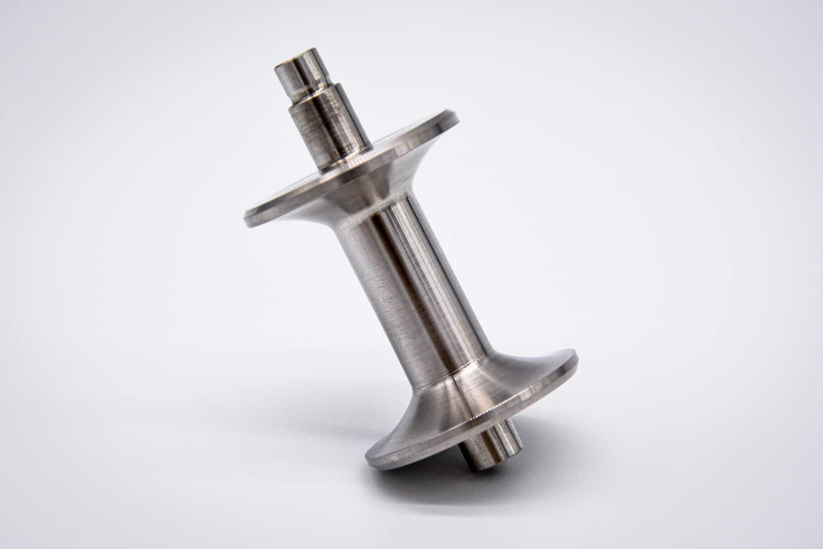
Deep Drawing
Deep drawing is a forming process that pushes a sheet metal blank through a die opening, stretching and compressing it to take the shape of the punch. It is used to create seamless parts with significant depth, such as cups, boxes, or enclosures. Shallow drawing is a similar operation with less depth.
How It Works
The process starts with a flat, pre-cut blank.
- A blank holder (or “pressure pad”) descends and firmly clamps the blank over the die cavity.
- The punch descends, pushing the center of the blank into the die.
- The blank holder maintains pressure, allowing the material to flow radially inward (to form the walls) while preventing wrinkling.
- The material is stretched and formed to the precise geometry of the punch and die.
Advantages and Limitations of Deep Drawing
| Advantages | Limitations |
| Creates Seamless, Strong Parts: Ideal for containers that must be watertight or airtight. Forms a continuous grain structure. | Very High Tooling Cost: The custom punch, die, and blank holder are complex and expensive to produce. |
| High-Volume Production: Once set up, the process is very fast and repeatable, making it excellent for mass production. | Material Limitations: Requires highly ductile and formable materials that can stretch without tearing. |
| Complex Geometries: Progressive deep drawing (using multiple stages) can create highly complex shapes. | Failure Risk: Prone to defects like tearing, wrinkling, or “earing” if process parameters are not perfect. |
Material Applications and Considerations
Deep drawing is only suitable for metals that can stretch and flow significantly without cracking. This includes low-carbon steels, many aluminum alloys (e.g., 3003), and stainless steel.
Success in deep drawing depends heavily on material quality and preparation.
- Uniform Thickness: The blank must have a consistent thickness to prevent thin spots that can tear.
- Burr-Free Blanks: Clean-cut, burr-free blanks are essential. Burrs from cutting can act as stress concentrators and initiate cracks.
- Lubrication: Proper friction control using lubricants (oils, polymer films) is critical to prevent galling (material sticking to the tool) and excess heat.
Tall parts, like a metal cup, may require multiple draws with an annealing (heat treatment) step in between to restore the material’s ductility before the next draw.
Industry Applications
- Automotive: Oil pans, fuel tanks, door panels, structural body components.
- Kitchen Appliances: Stainless steel sinks, cookware, range hoods.
- Packaging: Aluminum cans, food containers, aerosol cans, metal caps.
- Electronics: Enclosures, heat sink housings, battery cases.
Rolling
Rolling is a forming process that uses a series of rotating rolls to curve metal sheets into cylindrical or conical shapes. It is used to create consistent, large-radius curves that are not practical with press brake bending and have no limitations on part length.
How It Works
The most common machine configuration is a 3-roll bender, which has two support rolls at a lower level and an adjustable top roll that applies pressure to determine the bend radius. 4-roll machines are also common, as they add a fourth roll that helps pre-bend the leading and trailing edges of the sheet, eliminating the “flat spots” that 3-roll machines often leave.
The motorized rolls also feed the material through the machine. Correct sheet alignment is critical to ensure a straight, consistent cylinder. Depending on the target radius, the sheet may require several passes through the rolls to gradually achieve the final geometry.
Advantages and Limitations of Rolling
| Advantages | Limitations |
| Large, Consistent Radii: Creates smooth, large-radius curves that are impossible to make in one-shot on a press brake. | Minimum Radius Limit: The minimum achievable radius is limited by the diameter of the rolls and the material’s thickness. |
| No Length Limitation: Can form continuously curved parts, such as pipes or long tank sections. | Multiple Passes: Achieving a precise radius often requires multiple passes, which can be time-consuming. |
| Form Variety: Can be used to form conical and variable-radius shapes (with specialized machines). | Flat Spots: 3-roll machines tend to leave small, flat sections at the beginning and end of the sheet. |
| Thick Material: Well-suited for forming thick plates and structural shapes. | Simple Geometries Only: Limited to simple curved profiles. |
Material Applications and Considerations
Roll bending works well with most ductile sheet metals. The gradual, large-radius forming process significantly reduces the risk of cracking compared to sharp press brake bends.
The minimum bend radius is typically 3-5 times the material thickness, making rolling ideal for large curves. While “step bending” (creating a series of small, adjacent bends) on a press brake can simulate a large curve, it is not a true, smooth radius like rolling provides.
Rolling excels with materials thicker than 6 mm. For these heavy plates, rolling is a more efficient and effective method for creating large-diameter cylinders, tanks, and structural curves than other forming methods. Springback is minimal due to the gradual stress distribution, though soft materials like aluminum can be susceptible to marking from the rolls.
Assembling
Once parts are cut and formed, they are often joined into sub-assemblies or complete products. The choice of joining method affects the assembly’s strength, appearance, cost, and serviceability. Each method offers distinct trade-offs that must be considered against the project’s requirements.
Welding
Welding creates a permanent, high-strength joint by melting and fusing base materials together, often with the use of a filler material. It produces the strongest possible joint, and the processes range from precise, manual arc welding to high-speed, automated resistance welding.
Arc Welding Processes
Arc welding uses an electric arc to generate intense heat, melting the base metals and a filler material. A shielding gas is typically used to protect the molten weld pool from atmospheric contamination.
- TIG (Tungsten Inert Gas): Uses a non-consumable tungsten electrode and an inert gas shield. TIG welding offers excellent control over heat and weld quality, making it ideal for thin materials and applications requiring clean, precise welds (like stainless steel and aluminum). It is a manual process that is strong, flexible, but relatively slow.
- MIG (Metal Inert Gas): Uses a consumable wire electrode that is continuously fed through the torch, which also supplies the shielding gas. MIG welding offers a great balance of speed and quality, is easier to learn than TIG, and is well-suited for welding carbon steel, stainless steel, and aluminum.
- Stick Welding (SMAW): Uses a flux-coated consumable electrode. The flux creates its own shielding gas as it burns, eliminating the need for an external gas bottle. It is a simple, portable, and low-cost process ideal for outdoor work, but the weld quality cannot match that of TIG or MIG.
Resistance Welding Processes
- Spot Welding: Used to join overlapped sheets of metal without filler. An electric current is passed through the sheets while under pressure, creating a small, localized fused spot. It is a high-speed, automated process that dominates the automotive industry for body panel assembly.
- Seam Welding: Uses rotating wheel-shaped electrodes to create a series of overlapping spot welds, forming a continuous, leak-tight seam. It is commonly used for manufacturing fuel tanks, containers, and HVAC ducts.
Advantages and Limitations of Welding
| Advantages | Limitations |
| Highest Strength: Creates a continuous, fused joint that is typically as strong as the base metal. | Heat-Affected Zone (HAZ): The intense heat alters the material’s properties (e.g., strength, corrosion resistance) in the area around the weld. |
| Joins Dissimilar Thicknesses: Can effectively join a thick part to a thin part. | High Skill Required: Weld quality, especially with TIG, is highly dependent on operator skill. |
| Stiffness: Provides excellent load transfer and rigidity to an assembly. | Permanent: Joints cannot be disassembled for maintenance or repair without cutting. |
| Leak-Proof: Processes like TIG and seam welding can create hermetic seals. | Distortion (Warping): The high heat input can cause thin sheet metal parts to warp. |
Material Applications and Considerations
Most common metals can be welded, but the technique and filler must be chosen carefully.
- Carbon steel offers excellent weldability.
- Stainless steel requires careful heat control to prevent carbide precipitation, which reduces corrosion resistance.
- Aluminum is more difficult dueto its rapid oxide formation and high thermal conductivity, requiring a clean surface and proper gas shielding (typically with TIG or MIG).
A major limitation of welding is that surface coatings must be removed before welding. A part that is painted, powder-coated, or galvanized must be ground clean at the weld joint. This often adds complexity to the production workflow, requiring a part to go from fabrication (cutting/bending) to a separate welding specialist, and then to a third supplier for final coating.
Brazing and Soldering
Brazing and soldering are joining processes that look similar to welding but have one critical difference: they use a filler metal to create the joint without melting the base metals. This lower-temperature approach avoids many of the issues associated with welding.
How It Works
Both processes rely on capillary action to draw a molten filler metal into the tight gap between two closely-fitted parts. The filler metal bonds to the surfaces and solidifies, creating the joint.
- Brazing: Uses a filler metal with a melting point above 450°C. Common fillers include silver alloys and copper-phosphorus.
- Soldering: Uses a filler metal with a melting point below 450°C. Common fillers are tin-lead or lead-free alloys.
Advantages and Limitations of Brazing and Soldering
| Advantages | Limitations |
| Low Heat Input: Reduces the risk of distortion (warping) and does not create a large HAZ, preserving base metal properties. | Lower Strength: The joint strength is limited to the strength of the filler metal, not the base metal. |
| Joins Dissimilar Metals: An excellent method for joining dissimilar metals (e.g., copper to steel) that cannot be easily welded. | Precise Temperature Control: The process requires careful temperature control to melt the filler but not the base. |
| Clean Appearance: Can produce very clean, neat joints with minimal post-processing. | Flux Removal: The flux used to clean the surface must be thoroughly removed after joining to prevent corrosion. |
Material Applications and Considerations
Brazing and soldering are common for copper, brass, and many steels. Aluminum and stainless steel can be joined but require specific fluxes and filler alloys to deal with their protective oxide layers.
Soldering is generally used for thinner sheets (up to 3 mm for copper, less for steel), while brazing can be used on parts up to 6 mm thick.
Joint design is critical for both brazing and soldering. To allow for proper capillary action, the gap between the mating parts must be extremely small and consistent, typically in the 0.05 mm to 0.2 mm range.
Industry Applications
- Brazing:
- HVAC systems (e.g., refrigerant lines)
- Heat exchangers
- Aerospace components requiring leak-tight joints
- Soldering:
- Electronics assembly (PCBs)
- Light-duty mechanical connections and plumbing
Mechanical Fastening
Mechanical fastening is an essential joining method, distinct from welding. Its primary advantages are that it produces no heat-affected zone (HAZ), allows for joining dissimilar materials and coated parts, and can be performed after surface finishing.
Many mechanical fastening methods also create removable joints, allowing for disassembly, maintenance, and repair—a critical requirement in many product designs.
Bolting and Screwing
Threaded fasteners (bolts, screws, and nuts) create strong, reliable joints that are typically removable.
- Machine screws are used with nuts or pre-tapped holes.
- Self-tapping screws form (displace) their own threads during installation, which is ideal for creating a strong “bite” in thin sheet metal.
When a bolt and nut joint is properly tightened (preloaded), the parts are held together by compressive friction. This means the joint is strong in shear because the friction prevents sliding, not the bolt’s “shearing” strength. The bolt itself is primarily in tension, which is its strongest orientation.
Riveting
Riveting creates permanent joints by using a deformable fastener (a rivet) that is inserted into a hole and mechanically expanded to create a “head” on both sides.
- Solid rivets are simple and strong but require access to both sides for installation.
- Blind rivets (or “pop” rivets) are a a popular type of fastener in sheet metal fabrication as they can be installed from one side.
- Self-piercing rivets (SPRs) are a high-speed, automated process (common in automotive) where the rivet punches through the top sheet and flares into the bottom sheet, requiring no pre-drilled hole.
Clinching
Clinching is a high-speed, permanent joining method that is similar to spot welding and self-piercing riveting, but with one key difference: it uses no consumables (no fasteners or filler). A punch and die are used to draw and “clinch” the two layers of metal together, forming a strong, interlocking mechanical button. It is widely used in the HVAC and appliance industries.
Advantages and Limitations of Mechanical Fastening
| Advantages | Limitations |
| No Heat Input (No HAZ): Preserves material properties (strength, temper, corrosion resistance). | Stress Concentration: Loads are concentrated at the fastener holes, which can be a fatigue point. |
| Dissimilar Materials: Easily joins dissimilar metals (e.g., aluminum to steel) without galvanic corrosion issues (if fasteners are chosen correctly). | Hole Preparation: Most methods (except SPRs and clinching) require drilling or punching, which is an extra step. |
| Allows Disassembly: Bolts and screws create removable joints for service and repair. | Access Required: Many fasteners (like bolts and solid rivets) require access to both sides of the part. |
| Works on Coated Parts: Parts can be painted, powder-coated, or plated before assembly. | Corrosion Risk: Improper fastener selection can cause galvanic corrosion between dissimilar metals. |
| Simplicity: Many methods do not require highly skilled operators. | Added Weight: Fasteners add weight to the final assembly compared to a weld or adhesive. |
Material Applications and Considerations
Mechanical fastening works with virtually all sheet metal materials. However, material choice is critical for the fasteners themselves.
When joining dissimilar metals, or any metal in a corrosive environment, the fastener material is critical.
- To prevent galvanic corrosion, use a fastener made of a compatible material (e.g., use stainless steel fasteners for stainless steel parts, aluminum for aluminum).
- Processes like clinching and self-piercing riveting require ductile materials that can be formed without cracking.
Adhesive Bonding
Adhesive bonding uses structural adhesives to create strong, lightweight joints that distribute the load over a large surface area rather than concentrating it at a few points. Modern adhesives can be comparable in strength to mechanical fasteners and offer additional benefits like sealing against moisture and vibration damping.
How It Works
Structural adhesives (like epoxies, acrylics, and urethanes) form a chemical bond that cross-links to hold the parts together. The process generally involves three steps:
- Surface Preparation: This is the most critical step. Surfaces must be perfectly clean of oil, grease, and oxides. This may require solvent wiping, mechanical abrasion, or chemical etching.
- Application: A thin, controlled layer of the adhesive is applied.
- Curing: The adhesive solidifies through a chemical reaction, which may be triggered by time, heat, moisture, or UV light, depending on the adhesive type.
Advantages and Limitations of Adhesive Bonding
| Advantages | Limitations |
| Distributes Stress: Spreads the load over the entire bond area, reducing stress concentration and improving fatigue resistance. | Surface Preparation is Critical: Bond strength is highly dependent on meticulous surface cleaning and preparation. |
| Joins Dissimilar Materials: An excellent way to join different materials (e.g., metal to plastic) without galvanic corrosion. | Environmental Sensitivity: Bond strength can be degraded by high temperatures, humidity, or chemical exposure. |
| Seals Joints: Creates a continuous bond that can seal against moisture and contaminants. | Difficult to Disassemble: Joints are permanent and cannot be easily serviced or repaired non-destructively. |
| Aesthetically Clean: Provides a smooth external appearance with no visible fasteners or weld marks. | Difficult Quality Control: It is difficult to non-destructively inspect the quality or strength of a bond. |
| Lightweight: Adds minimal weight compared to fasteners. | Cure Time: Requires time to cure (from minutes to hours), which can slow down production throughput. |
Material Applications and Considerations
Structural adhesives can bond all common metals, including aluminum, stainless steel, and carbon steel, but only if the surface is prepared correctly. Oily or oxidized surfaces will cause the bond to fail.
Unlike other joining methods, the success of adhesive bonding is 90% preparation. The surface must be clean, dry, and free of all contaminants (like oil, rust, or heavy oxides). For structural applications, this often means abrading (sanding) the surface or applying a chemical primer to ensure the adhesive can achieve a proper chemical bond.
Post-Processing: Finishing and Coating
Post-processing is the final stage of fabrication, broken into two key phases. The first is surface finishing , which mechanically removes imperfections like sharp edges, dross, or burrs left by cutting and forming. The second is applying protective coatings to protect the assembly from its environment, ensuring a long service life.
Surface Finishing
Surface finishing is the mechanical treatment of a part’s surface to remove flaws, improve the finish, and prepare it for a final coating.
Deburring
Deburring is a fundamental operation to remove the sharp edges and burrs created during cutting, punching, and forming.
Manual deburring is still quite common, using files, scrapers and other abrasive tools for edge treatment.
Tumbling uses abrasive media in a rotating drum to uniformly remove burrs from batches of (usually smaller) parts, providing a consistent texture.
Electrochemical deburring, a process mirroring electroplating in reverse, removes burrs. This occurs as an electric current and electrolyte flow cause material to detach from the workpiece.
Polishing and Grinding
Grinding uses a bonded abrasive (wheel, belt, or disc) to cut away metal. It is a more substantial process than deburring and is often used to smooth rough areas (like welds) or prepare an entire surface for coating.
Polishing is a finer process that refines the surface, resulting in a smoother, brighter appearance. For metals like stainless steel that do not require a coating, polishing can be the final step. It reduces microscopic roughness, which inhibits the growth of bacteria and other contaminants, making the part easier to sanitize.
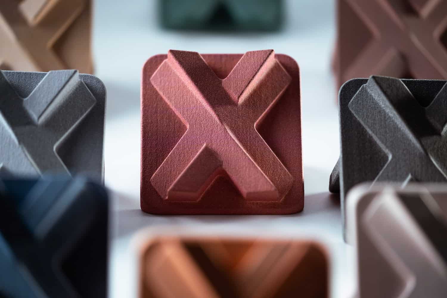
Protective Coatings
Most metals will oxidize (rust) or corrode when exposed to the environment. Protective coatings are applied to ensure the part’s structural and functional integrity over its lifetime.
Powder Coating
Powder coating is a common, highly durable finish. A dry, colored powder is electrostatically charged and sprayed onto a grounded metal part . The part is then cured in an oven, where the powder melts and flows into a uniform, resilient layer, typically 25–100 micrometers thick. It offers excellent resistance to impact and abrasion, far superior to most wet paints.
Wet Painting
Modern liquid painting uses spray guns (airless, air-assisted, or electrostatic) to apply multiple layers. A typical system includes a primer for adhesion and corrosion protection, followed by a topcoat that provides color, gloss, and environmental resistance.
Galvanizing
Galvanizing is a process of applying a protective zinc coating to steel.
- Hot-Dip Galvanizing: Immerses the steel part in a bath of molten zinc, creating a thick (45–85 µm), durable, and metallurgically bonded coating. This coating is famously “self-healing”; if the surface is scratched, the surrounding zinc will corrode first, sacrificially protecting the exposed steel.
- Electrogalvanizing: Uses an electroplating process to deposit a much thinner (5–25 µm) zinc coating, offering a brighter finish and better dimensional control for precision parts.
Anodizing
Anodizing is an electrochemical process used specifically for aluminum. It creates a controlled, hard layer of aluminum oxide on the surface, which provides excellent corrosion resistance without adding significant thickness.
| Type | Method | Key Features |
| Anodizing Type I | Chromic Acid | Very thin (up to 2.5 µm). Used for minimal dimensional change[cite: 802, 803]. |
| Anodizing Type II | Sulfuric Acid | Standard (2.5–25 µm). The most common type, good for corrosion resistance and decorative color[cite: 804]. |
| Anodizing Type III | Sulfuric Acid (Hardcoat) | Thick and very hard (25–100 µm). Provides excellent wear and abrasion resistance[cite: 805]. |
Electroplating
Electroplating is a process that deposits a thin metallic layer onto a workpiece. This can be for decorative or functional purposes, such as nickel plating (for appearance) or chrome plating (for extreme hardness and wear resistance). It offers excellent control over coating thickness, making it ideal for precision applications.
A Process for Every Design: Sheet Metal
Understanding the full spectrum of sheet metal fabrication processes is essential for cost-effective and functional design. The choices made at the very beginning—from material selection to part geometry—will directly influence which cutting, forming, and finishing options are available.
An engineer who considers the entire manufacturing chain, from standard sheet size to the final protective coating, is best equipped to design parts that are not only functional but also reliable and economical to produce.


Comment(0)