

 Europe
 Türkiye
 United Kingdom
 Global


 Login with my Xometry account


ASME Y14.5-2009 listed it among 14 geometric tolerances. ASME Y14.5-2018 no longer supports symmetry or concentricity, which leaves position as the only location tolerance and 12 tolerances grouped into form, orientation, location, profile and runout. ISO 1101 still includes symmetry, so readers working to ISO drawings will continue to see it.
| Standard | Symmetry status | Notes |
| ANSI Y14.5M-1982 | Not included | Symmetrical relationships were specified with position |
| ASME Y14.5M-1994 | Included | Already discouraged in favor of position |
| ASME Y14.5-2009 | Included | One of 14 tolerances; regardless of feature size only |
| ASME Y14.5-2018 | Removed | No longer supported; 12 tolerances remain |
| ISO 1101 | Included | Applies to the extracted median surface; two-parallel-plane zone; can carry a material requirement |
GD&T trainers attribute the removal to widespread misapplication and costly inspection. Symmetry cannot be verified with a functional gauge, and trainers note that the 1994 and 2009 editions already discouraged it. Legacy prints still carry the symbol and many organizations still work to Y14.5-2009, so reading it correctly remains valuable.
What Is Symmetry in GD&T?
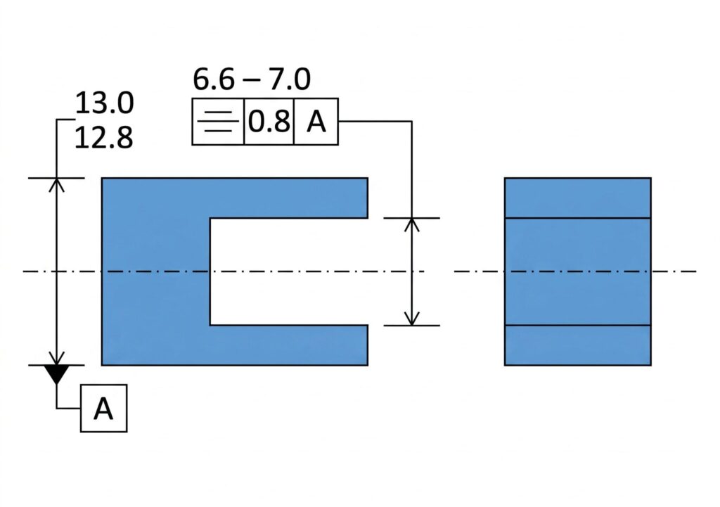
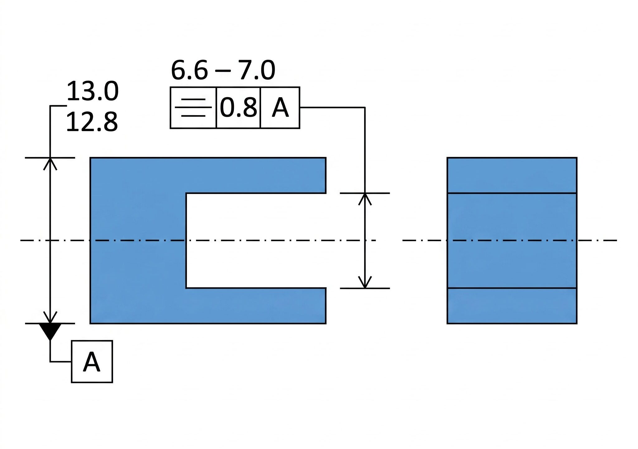
Symmetry is the condition where the median points of all opposed or correspondingly located elements of two or more feature surfaces are congruent with a datum axis or center plane. It applies to features such as slots, tabs and keyways.
A median point is the midpoint between a pair of opposed points on the controlled surfaces. Symmetry evaluates these median points, not the surfaces themselves and not the center plane of the feature’s actual mating envelope. Under Y14.5-2009, symmetry applies only regardless of feature size (RFS), and its datum reference applies only regardless of material boundary (RMB).
Because only median points count, symmetry does not control the form or orientation of the walls on its own. Equal and opposite errors cancel at the median point, so the walls can taper toward or away from each other and still satisfy symmetry. The size tolerance on the slot width still limits how far they can move.
The tolerance therefore suits only the rare case where the distribution of median points about the center plane is itself the functional requirement.
Calculating a median point for every opposed pair makes symmetry difficult and expensive to inspect. Manual checks are possible but impractical, and a coordinate measuring machine (CMM) is typically needed.
Real-world example: The motor shaft keyway
Consider the keyway on a motor shaft that connects a motor to a pump. The keyway must be wide enough to house the key, and it must sit centered about the shaft’s axis. An off-center keyway shifts the key away from the axis, which can misalign the keyed component.
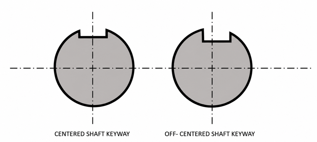
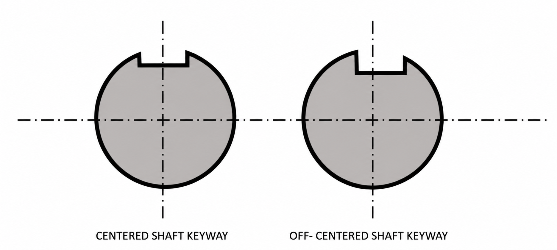
A designer working to Y14.5-2009 could apply symmetry to the keyway, referenced to the shaft axis. That standard already offered a choice: position, profile and symmetry could each control a symmetrical relationship, and each set a different requirement. Under Y14.5-2018, the usual replacement is position applied to the keyway width as a feature of size. Position controls the center plane of the keyway’s unrelated actual mating envelope rather than median points, and it can be applied at maximum material condition (MMC).
Why position and profile replaced symmetry
Position at MMC gives bonus tolerance as the feature departs from MMC, and it can be verified with a functional gauge. Neither is possible with symmetry, which is locked to RFS.
Profile does a different job. It controls the actual surfaces directly, so tapered or wavy walls whose errors would cancel in a median-point check are caught.
Symmetry Tolerance Zone
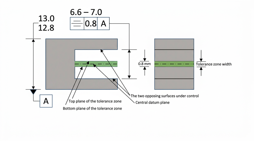
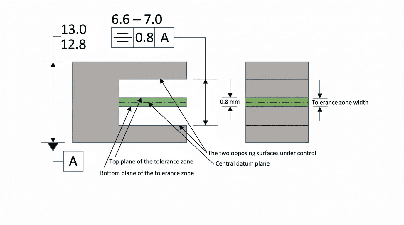
In GD&T, a tolerance zone is the region within which the controlled feature or derived element must lie. For symmetry, the zone is two parallel planes equally disposed about the datum center plane. On a keyway, that center plane contains the shaft’s axis.
All median points must lie between the two planes; the walls themselves need not. A 0.8 mm zone places each boundary plane 0.4 mm from the datum center plane. Unlike controls with several zone shapes, symmetry always uses two parallel planes.
Symmetry takes no material condition modifier, so no bonus tolerance exists. The zone stays fixed whether the feature is at MMC, at least material condition (LMC) or anywhere between.
Symmetry Feature Control Frame
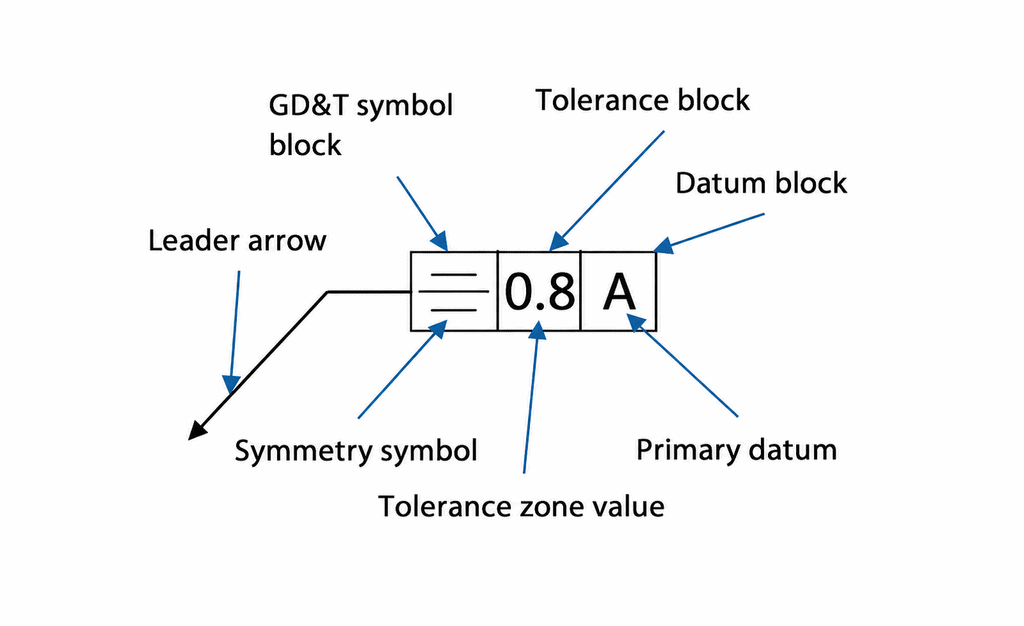
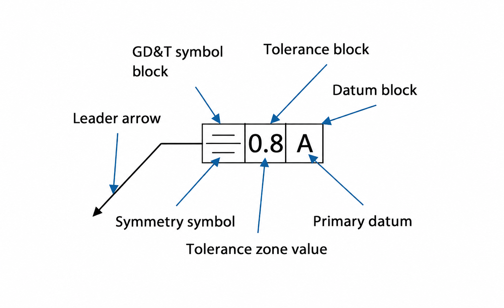
All GD&T tolerances appear on engineering drawings in a feature control frame. The frame is divided into compartments (often called blocks) that state which tolerance applies, its magnitude and the datums it relates to.
| Compartment | What it states | For symmetry |
| Geometric characteristic symbol | The tolerance applied | Three horizontal lines, the middle one longer |
| Tolerance | The width of the zone | Distance between the two parallel planes. No zone-shape symbol and no modifier, since RFS is the only option |
| Datum feature reference | The datum feature reference that establishes the datum center plane or axis | Commonly one datum feature that establishes the center plane or axis, applied RMB. Further datum references can orient the zone when needed |
A frame reading ⌯ | 0.8 | A requires every median point of the controlled surfaces to lie between two parallel planes 0.8 mm apart, centered on datum A.ISO 1101 allows a datum system as well.
Symmetry vs. Alternative Callouts
Symmetry addressed a real need: keeping slots, tabs and keyways centered about a datum. The tables below compare it with the three closest callouts.
Symmetry vs. concentricity
| Aspect | Symmetry | Concentricity |
| Applies to | Opposed surfaces such as slots and tabs | Surfaces of revolution |
| Evaluates | Median points of opposed elements about a datum center plane or axis | Median points of diametrically opposed elements about a datum axis or center point |
| Zone | Two parallel planes | Cylinder or sphere |
| ASME status | Removed in Y14.5-2018 | Removed in Y14.5-2018 |
Both evaluate median points rather than the actual surface, and both were commonly misapplied. Trainers cite balance and mass distribution as the typical reason to choose concentricity, although runout or position usually meets the need. In ISO 1101, concentricity controls a center point in a cross section and coaxiality controls an axis.
Symmetry vs. position
| Aspect | Symmetry | Position |
| Controls | Median points of opposed surfaces | Center plane or axis of the feature’s unrelated actual mating envelope |
| Surface form | Not controlled by symmetry itself; the size tolerance limits it | Not controlled by position itself; the size tolerance limits it |
| Material condition | RFS only, no bonus tolerance | RFS, MMC or LMC; bonus tolerance at MMC or LMC |
| Inspection | CMM with many point pairs | Functional gauge at MMC, or CMM |
| ASME status | Removed in Y14.5-2018 | Current; the only location tolerance in Y14.5-2018 |
Most features that once carried symmetry can be toleranced more efficiently with position.
Symmetry vs. profile
| Aspect | Symmetry | Profile |
| What it controls | Median points only | The actual surfaces |
| Effect on wall form | None on its own; equal and opposite errors cancel | Form, and with datums also orientation and location |
| Inspection | CMM, many point pairs | CMM or scanning compared with the CAD model |
For some features, symmetry’s median points fall inside the part or in an inaccessible location, which adds to the difficulty. Profile of a surface avoids that by controlling the surfaces themselves.
How to Measure Symmetry
Symmetry is one of the most difficult GD&T tolerances to inspect. It needs many opposed point pairs, a median point for each pair, and a check that every median point lies within the zone. It is typically measured on a CMM.

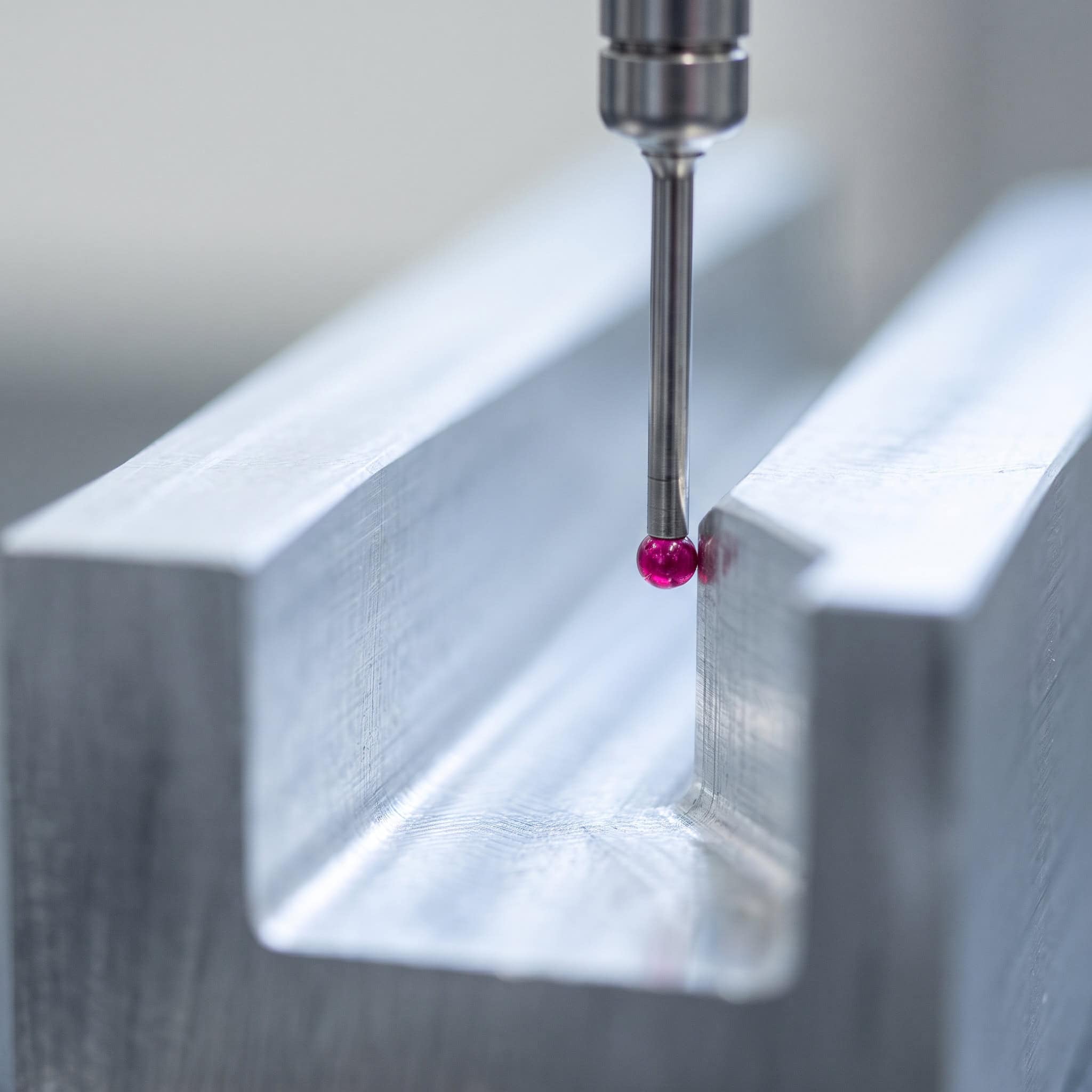
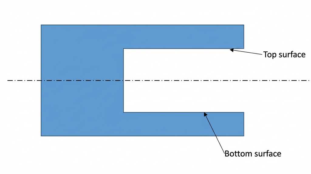
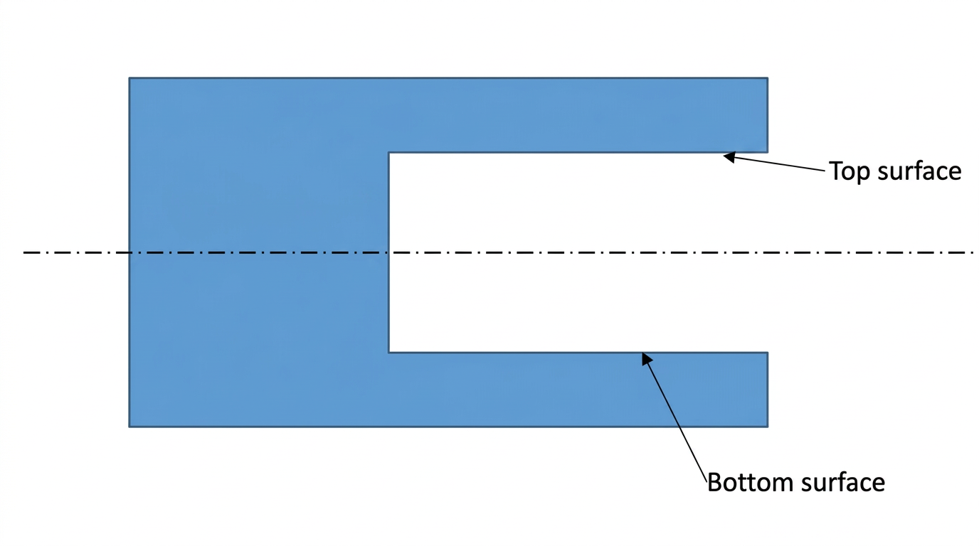
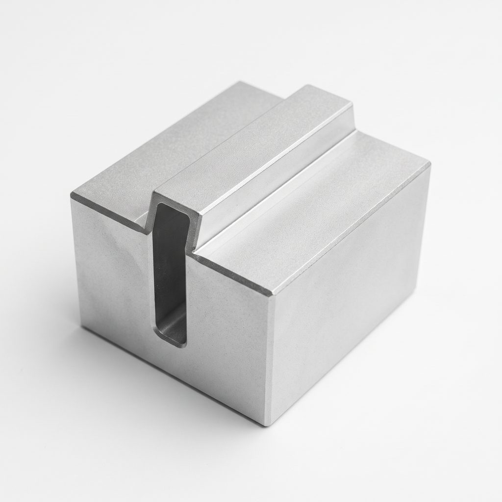
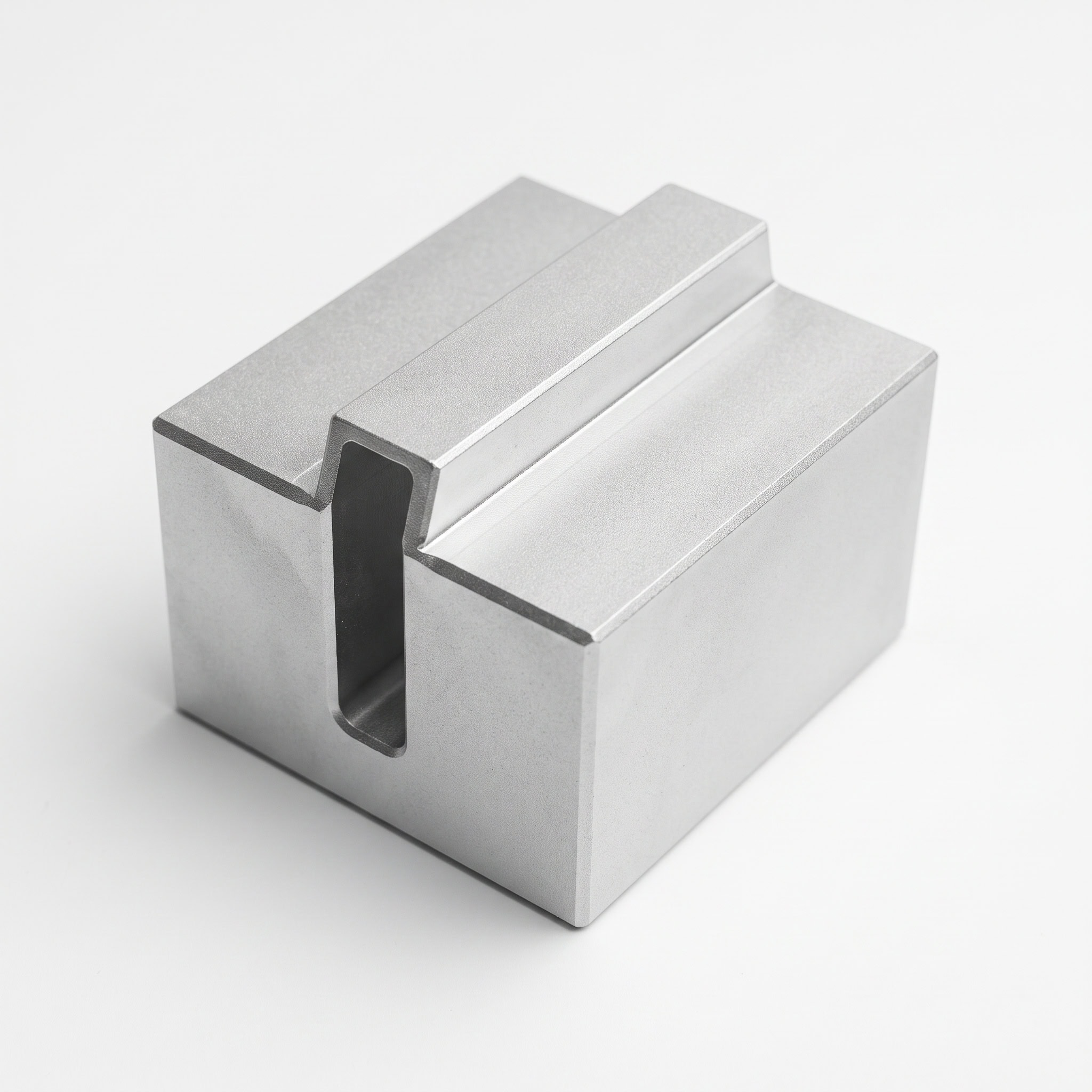
For the part shown in the first figures, datum A is the center plane of the 12.8 to 13.0 mm width, and the controlled feature is the 6.6 to 7.0 mm slot.
- Establish the datum. Measure the outer width and establish datum A, its center plane.
- Measure the foremost cross section. Probe the lower slot wall at equal intervals along its full length.
- Measure the opposed wall. Probe the upper slot wall at the same positions, then calculate the median point of each opposed pair.
- Repeat through the depth. Repeat the pattern at each cross section until the last one is measured.
- Evaluate all median points together. Every median point must lie within the 0.8 mm zone centered on datum A. One point outside fails the part.
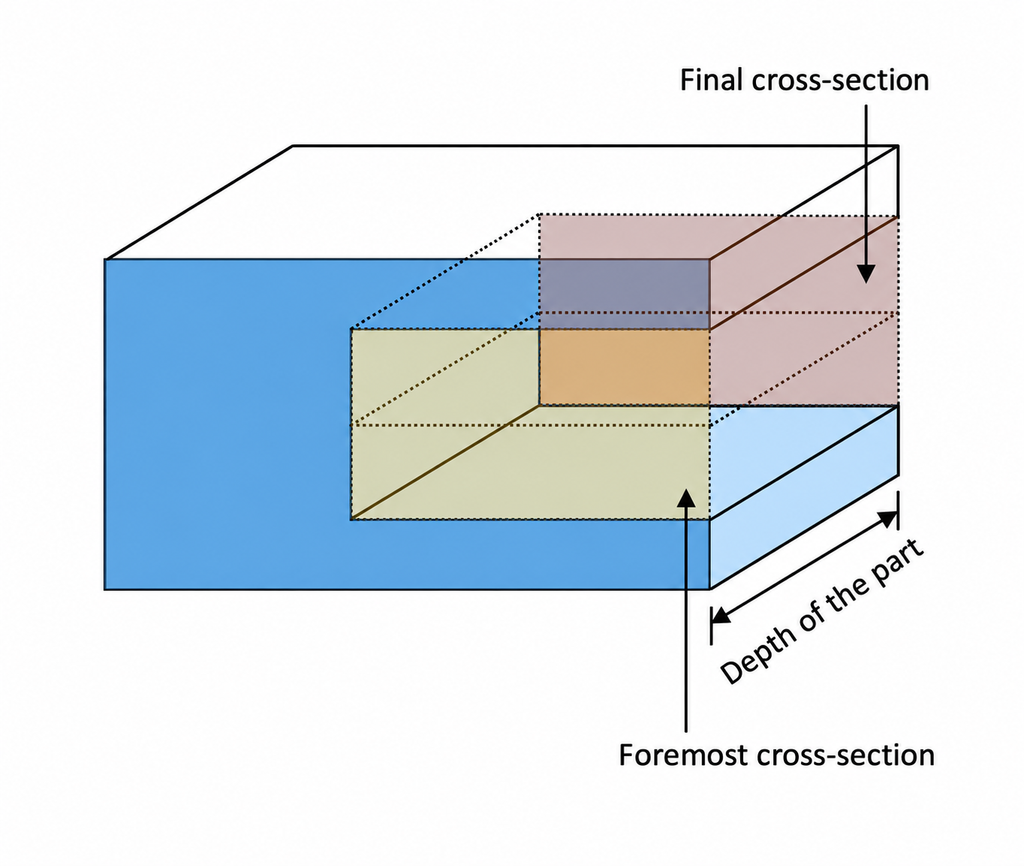
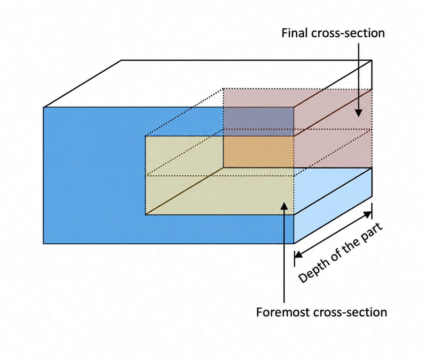
The callout defines what is evaluated; the sampling density is set in the inspection plan. Sparse sampling tends to understate the error, because the worst median point can fall between measured pairs. Long or critical features therefore call for dense probing or continuous scanning.
Conclusion
Symmetry survives on legacy ASME drawings and in ISO 1101, so designers and inspectors still need to read it. On a new ASME Y14.5-2018 drawing, apply position to the feature width, or profile of a surface where the walls themselves matter. Round features that once used concentricity take position or runout instead. The guide to preparing an engineering drawing shows how to present these callouts clearly.
Related Topics
 Contact VED
 2
2






Comment(0)