 Europe
  Türkiye
  United Kingdom
  Global

Injection molding wall thicknesses - tips?
R
Hello,
I am a mechanical engineer currently in the design phase of developing rectangular housings using PA66 GF30 material. From my previous projects, I’ve encountered challenges with achieving consistent dimensions, particularly with thin wall sections. In my current design, a critical feature has a specified wall thickness of 0.7mm, which I suspect might lead to warping and strength issues based on past experience.
To preemptively address potential problems, I am considering adjusting the wall thickness. However, this could affect the overall width, initially designed at 80.0mm (+/-0.05mm).
- What is the generally recommended minimum wall thickness for injection molding of PA66 GF30 to ensure structural integrity without compromising dimensional accuracy?
- Given the stringent tolerances required, would it be appropriate to adhere to ISO 20457 for general tolerances in this situation, which is specifically tailored for injection molded plastic parts?
I would appreciate any insights or suggestions on how to best approach this design challenge.

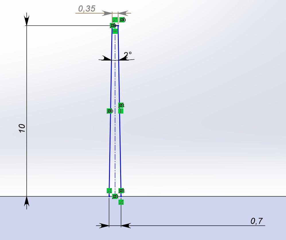
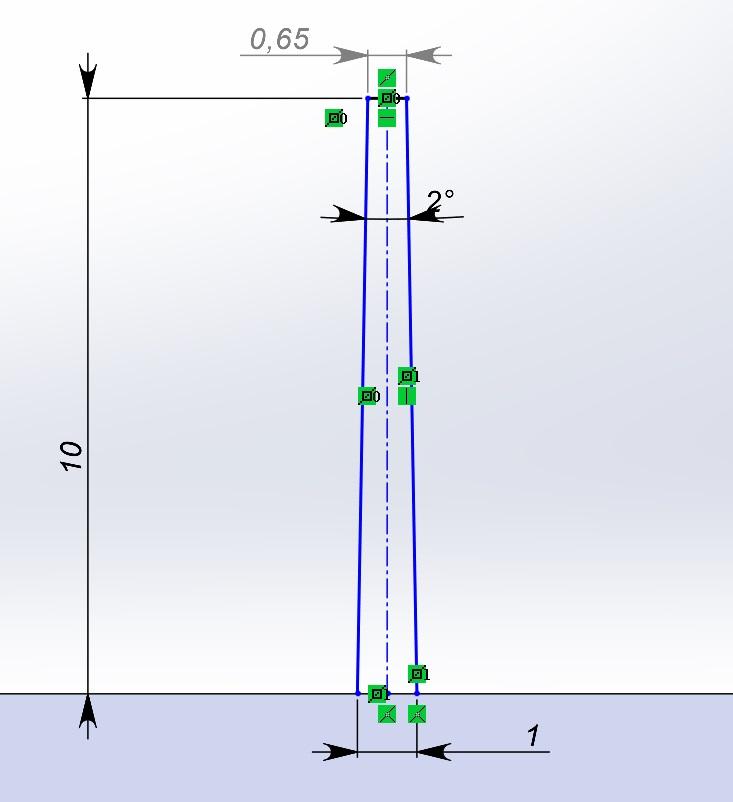
 As you can see in the picture, with a thickness of 1 mm you get a pretty good result at the top of the rib.
 I hope this is helpful to you,
have a good day :-)
I hope this is helpful to you,
have a good day :-)
Suggested Topics
Topic
Replies
Views
Activity
DFM check: Is this part a “nightmare” to machine?
Hi! Designing a custom housing for a prototype. I’ve got features on all six sides, and I’m realizing this is going to need a ton of CNC setups. In your experience, is it better... read more
0
29
Robust actuator-to-brake pedal joint for angled, high-force actuation
hi, i am designing a push-rod connection between a linear actuator and a vehicle brake pedal for a durability test setup. The actuator can apply 750 N, and the pedal rotates through its travel,... read more
12
161
Mar 16
Flatness GD&T for 6061 plates
For a mounting plate for a precision sensor (about 200 mm × 200 mm) I was going to call out a flatness of 0.05 mm, but my senior engineer says that’s overkill and will double the machining... read more
3
337
Mar 14
ISO 2768-mK vs specific tolerances
Hey guys, I’m getting some pushback from our shop lead. I’ve been dimensioning every single feature on a new manifold block because I’m paranoid about fitment, but he says the drawing is "unreadable" and... read more
2
450
Mar 14