 Europe
  Türkiye
Selective Laser Sintering (SLS) and Multi Jet Fusion (MJF) are two of the most widely used powder bed fusion (PBF) 3D printing technologies for polymers and elastomers.

SLS and MJF are very similar in process and workflow, capable of producing nearly identical parts. MJF, with its isotropic properties and slightly higher print resolution, is ideal for smaller functional parts. SLS, offering a wider range of materials and larger build volumes, is better suited for visual prototypes and medium-sized functional parts. Both processes are comparable in printing cost and speed, but MJF is more cost-effective for larger production volumes and slightly faster due to its faster cooling time and ability to reuse more powder.
3D Printing Technologies Description
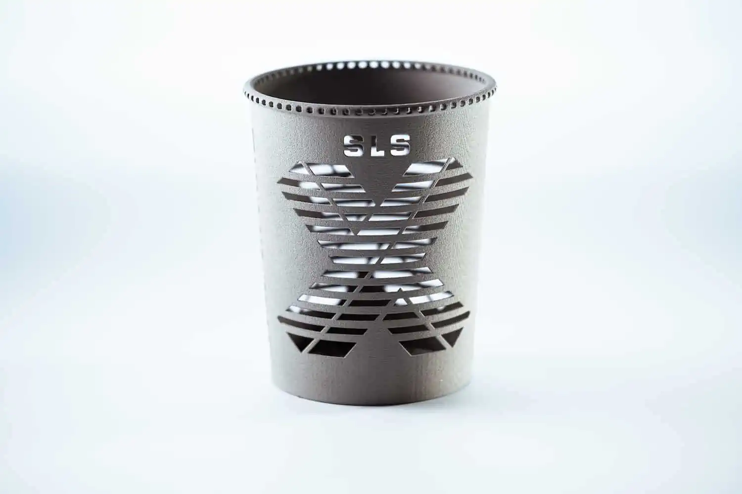
Selective Laser Sintering
Selective laser sintering is a powder-bed 3D printing technique used for creating parts from thermoplastic materials such as PA 12 and PA 11. This process involves a CO2 laser selectively fusing plastic powder by tracing each cross-section of the part, layer by layer. After sintering each layer, the print bed lowers, and a new layer of powder material is applied.
The term “sintering” describes heating the plastic particles until their surfaces melt and adhere to each other. SLS is a well-established technology that supports a broad range of materials (including food-grade, flame-retardant materials), making it more versatile compared to newer methods like MJF.

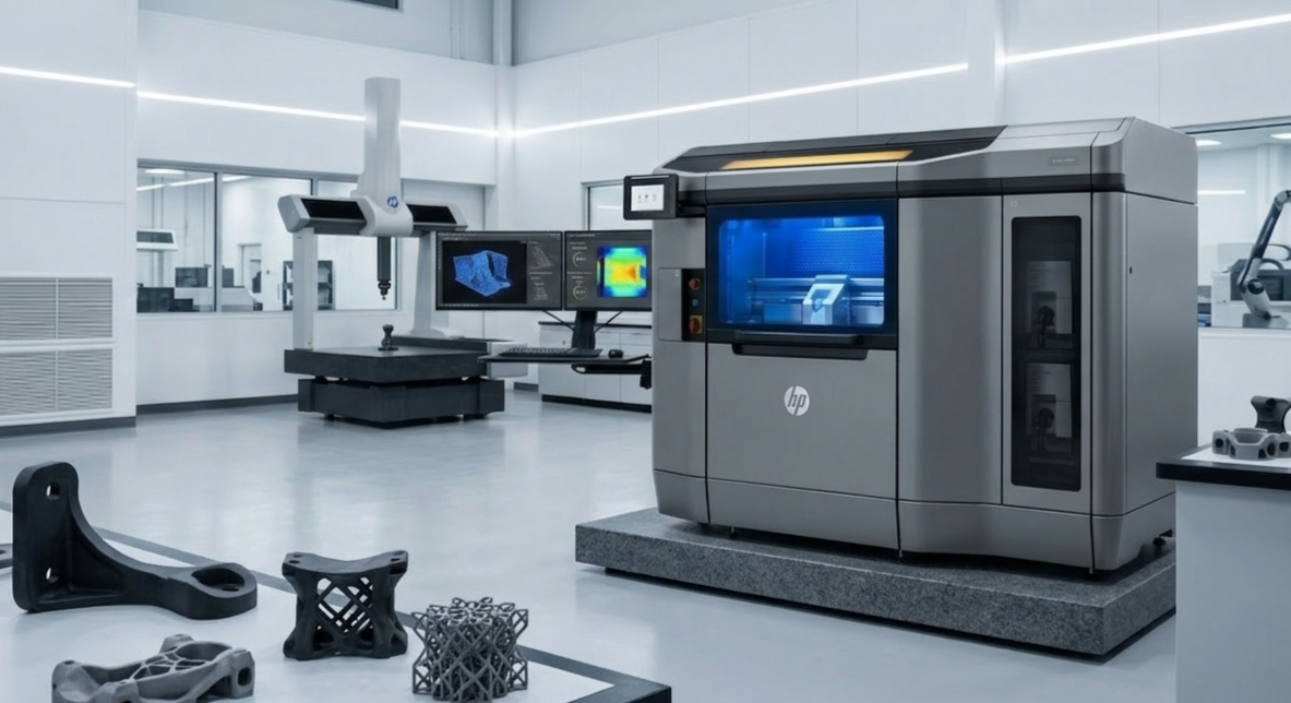
Multi Jet Fusion
HP Multi Jet Fusion is a powder-bed 3D printing technology developed by Hewlett-Packard in 2016. It involves a multi-step process where a thin layer of powder is spread on the print bed and heated just below its sintering point. A fusing agent is then applied to form the cross-section of the part, followed by a detailing agent to enhance edge sharpness.
An infrared heat source passes over the treated powder, sintering the particles to create the part. MJF is designed for higher production rates and offers advancements over SLS in speed and precision.

Differences Between MJF and SLS 3D Printing
MJF vs. SLS Materials
MJF and SLS extensively use polyamides such as Nylon 11 and Nylon 12, along with thermoplastic polyurethane (TPU) and polypropylene. The SLS technology is also capable of printing with carbon- and aluminium-filled nylons, and specialized high-temperature SLS machines, like those from EOS, can handle engineering thermoplastics such as PEEK. SLS is also compatible with food-grade variants of PA 11 and PA 12, in addition to a UL 94 V-0 rated PA 12 material (PA 2210 FR.
In contrast, MJF is currently limited to fewer materials, primarily Nylon 12, Nylon 11, and TPU. However, MJF also offers Nylon 12 with options such as a 40% glass-filled variant for enhanced strength.
The following table compares common materials used in MJF and SLS technologies:
| Material | 3D printing technology |
Tensile strength (MPa) |
Elongation at break (%) |
Heat deflection temperature (0.45 MPa) (°C) |
Density (g/cm³) |
|---|---|---|---|---|---|
| Nylon 12 / PA 12 | SLS | 50 | 11 | 171 | 1.01 |
| Nylon 12 / PA 12 | MJF | 48 | 20 | 175 | 0.93 |
| Nylon 11 / PA 11 | SLS | 49 | 40 | 182 | 1.03 |
| Nylon 11 / PA 11 | MJF | 52 | 50 | 185 | 1.05 |
| Nylon 12 (PA 12) glass-filled | SLS | 38 | 4 | 170 | 1.22 |
| Nylon 12 (PA 12) glass-filled | MJF | 30 | 10 | 174 | 1.30 |
| Alumide® / Nylon 12 (PA 12) filled with aluminium | SLS | 48 | 4 | 175 | 1.36 |
| Nylon 12 flame retardant / PA 2241 FR | SLS | 49 | 15 | 154 | 1.00 |
| Nylon 12 full-colour / CB PA 12 | MJF | 46 | 20 | N/A | 1.03 |
| PA 11 food grade (blue) | SLS | 53 | 20 | N/A | 1.02 |
| PA 12 food grade (white) | SLS | 48 | 15 | N/A | 0.93 |
| Polypropylene (PP) | MJF | 30 | 20 | 100 | 0.89 |
| Polypropylene (PP) | SLS | 29 | 34 | 113 | 0.84 |
| Flex TPU | SLS | 7.2 | 310 | N/A | 1.14 |
| TPU (Polyurethane) | MJF | 10 | 291 | N/A | 1.1 |


SLS vs. MJF Strength
When comparing the strength of SLS vs. MJF parts, it’s essential to consider factors such as material properties, printer settings, and design techniques. SLS parts are known for their robust mechanical properties, but they tend to exhibit anisotropic behavior, meaning their strength varies depending on the direction of the applied load (X/Y, Z). In contrast, MJF produces parts with relatively consistent mechanical properties due to their more isotropic nature, ensuring uniform strength and durability in all directions.
Additionally, the printer settings, such as layer thickness and fusion parameters, significantly impact the final strength of both SLS and MJF parts. For instance, adjusting the layer thickness to a finer resolution can improve part detail and strength, while fine-tuning the fusion parameters can ensure better bonding between layers. Ensuring proper part orientation and using appropriate cooling cycles also contribute to reducing internal stresses and warping.
Additionally, both technologies allow for the hollowing of parts, which can maintain structural integrity while reducing material usage. However, it’s important to note that MJF parts with wall thicknesses above 7 mm are often hollowed by default, which can compromise their strength and make them more prone to breaking under pressure. Alternatively, integrating cores, ribs or even lattice structures can enhance the mechanical strength of the part without the need for overly-thick features.

Dimensional Accuracy and Feature Resolution
Both MJF and SLS offer high dimensional accuracy, but there are some differences in their feature resolution. MJF parts have a finer feature resolution of 0.51 mm compared to SLS, which has a resolution of 0.762 mm.
SLS and MJF technologies do not require support structures, enabling the creation of custom models without support removal marks. However, both are prone to warping, so it is better to avoid large, flat areas in your design.
| Property | SLS | MJF |
| Tolerance | ±0.3% (lower limit ±0.3 mm) | ±0.3% (lower limit ±0.2 mm) |
| Minimum wall thickness | 0.5 mm (supported), 0.6 mm unsupported | 0.6 mm (supported), 0.7 mm unsupported |
| Layer thickness | ~0.1 mm and for water-tight parts 1.5 mm, when wall thickness is higher | ~0.08 mm |
| Minimum feature size | 0.6 – 0.8 mm | 0.5 mm |

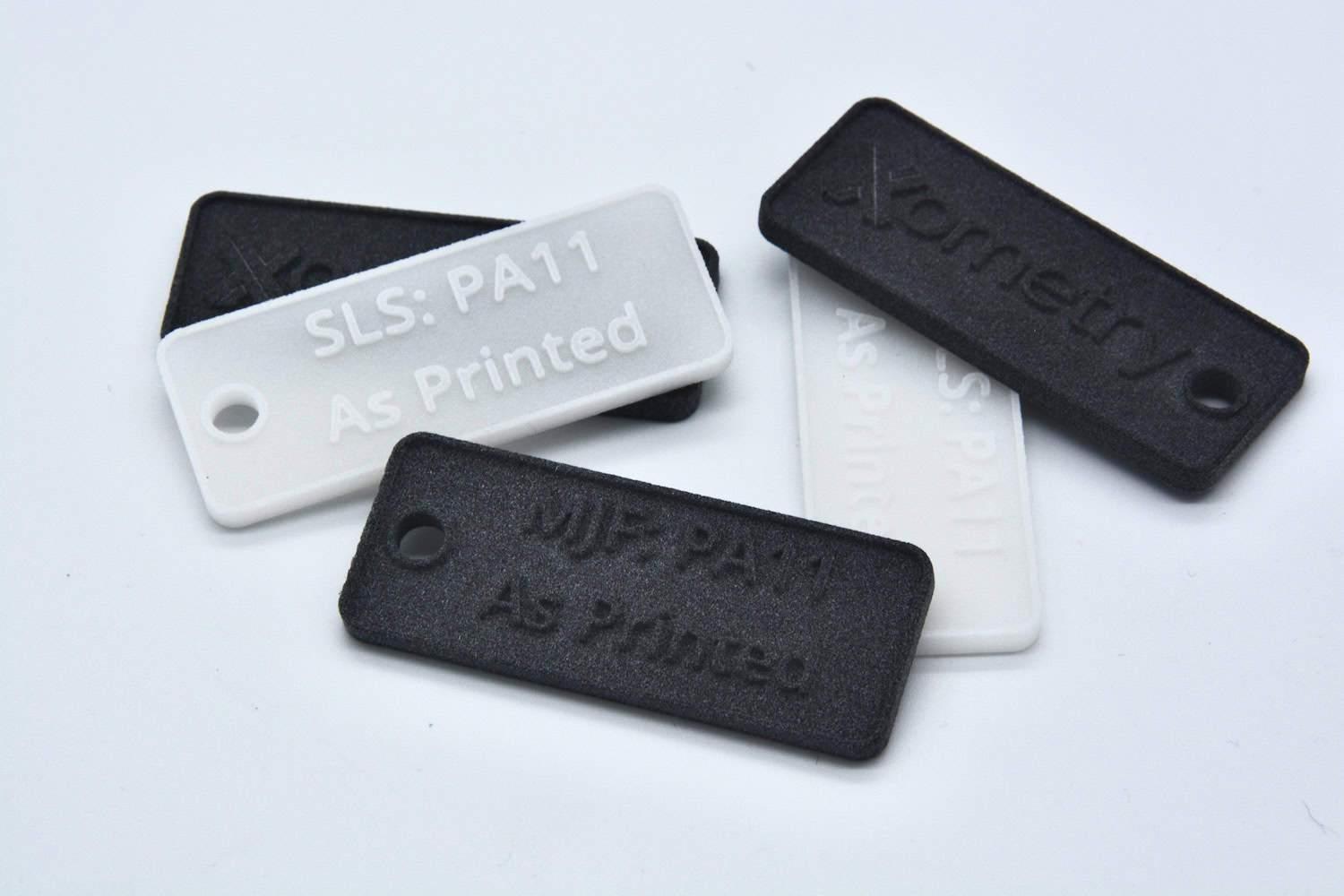
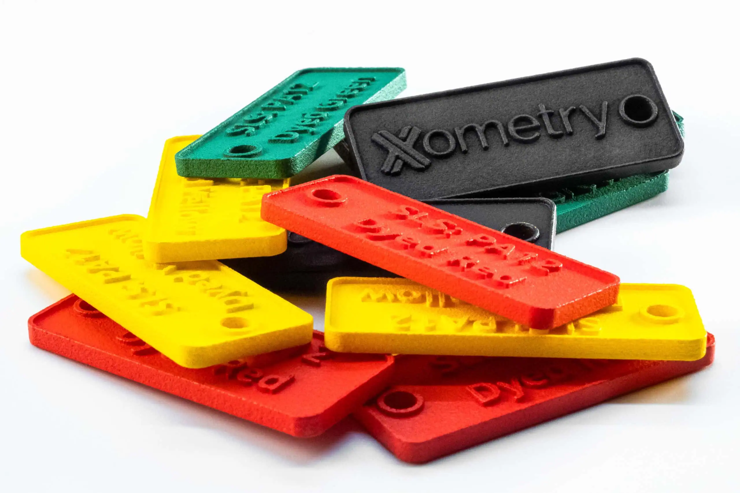
MJF vs. SLS Surface Finish
SLS and MJF produce parts with a characteristic rough/matte surface finish. However, the surface can be smoothened via bead blasting (SLS only) and media tumbling. Additionally, chemical vapor polishing has made it possible to achieve sealed, semi-gloss surfaces at low costs for either process.
Common surface finish options for MJF:
- Media tumbling
- Vapor smoothing (+dyeing/spray painting)
- Dyeing
- Spray painting
Common surface finish options for SLS:
- Media tumbling
- Bead blasting
- Vapor smoothing (+dyeing/spray painting)
- Dyeing
- Spray painting


The table below illustrates the changes in PA 12 surface roughness based on the additive manufacturing technology used and the surface finish applied to the part:
| Material | 3D printing technology | Surface finish | Roughness (Ra) | Roughness (Rz) |
| PA 12 | MJF | As printed | 10 – 12 µm | 59.9 – 69.4 µm |
| PA 12 | MJF | Chemical vapour polished | 4.4 µm | 31.1 µm |
| PA 12 | MJF | Dyed black | 5.8 µm | 38.7 µm |
| PA 12 | SLS | As printed | 9 µm | 55.1 µm |
| PA 12 | SLS | Bead blasted | 4.5 µm | 31.6 µm |
| PA 12 | SLS | Dyed black | 7.5 µm | 47.6 µm |
| PA 12 | SLS | Media tumbled | 7.1 µm | 45.5 µm |
| PA 12 | SLS | Vapor polished + dyed black | 2.5 µm | 19.7 µm |

Processing Time
MJF’s printing process takes the same amount of time per layer versus SLS, in which layer time is dictated by the complexity of the cross-section for the laser to scan. In net, MJF builds are faster than SLS and the output results shine in volume production of parts because more builds can be exchanged per machine versus SLS. Both processes allow print beds to cool outside the machine, with cooling time typically requiring 10-20 hours, depending on nested density. While a build frame is cooling, a new frame can be inserted into the machine to start a new build.
In both SLS and MJF operations, three frames are recommended for every machine: one is printing, one is cooling, and one has cooled parts broken out for processing. This setup allows the best utilization of the machine with little downtime.
Print Volume
SLS machines can produce parts with larger build volumes (up to 550 x 550 x 750 mm) compared to MJF printing (up to 380 x 284 x 380 mm). But in both cases, it is not recommended to make parts as large as the available build area, as this can create thermal conditions that can affect the part (warping, twisting, shrinking, etc.) and increase the risk of build failure (peeling/snagging of the recoater).
To maximize efficiency in SLS printing, it is crucial to utilize the entire build volume, as the process allows for minimal powder recycling (80% of the powder recovered from MJF printed parts is recyclable, compared to SLS with 30–50% recyclability).
MJF vs. SLS Cost
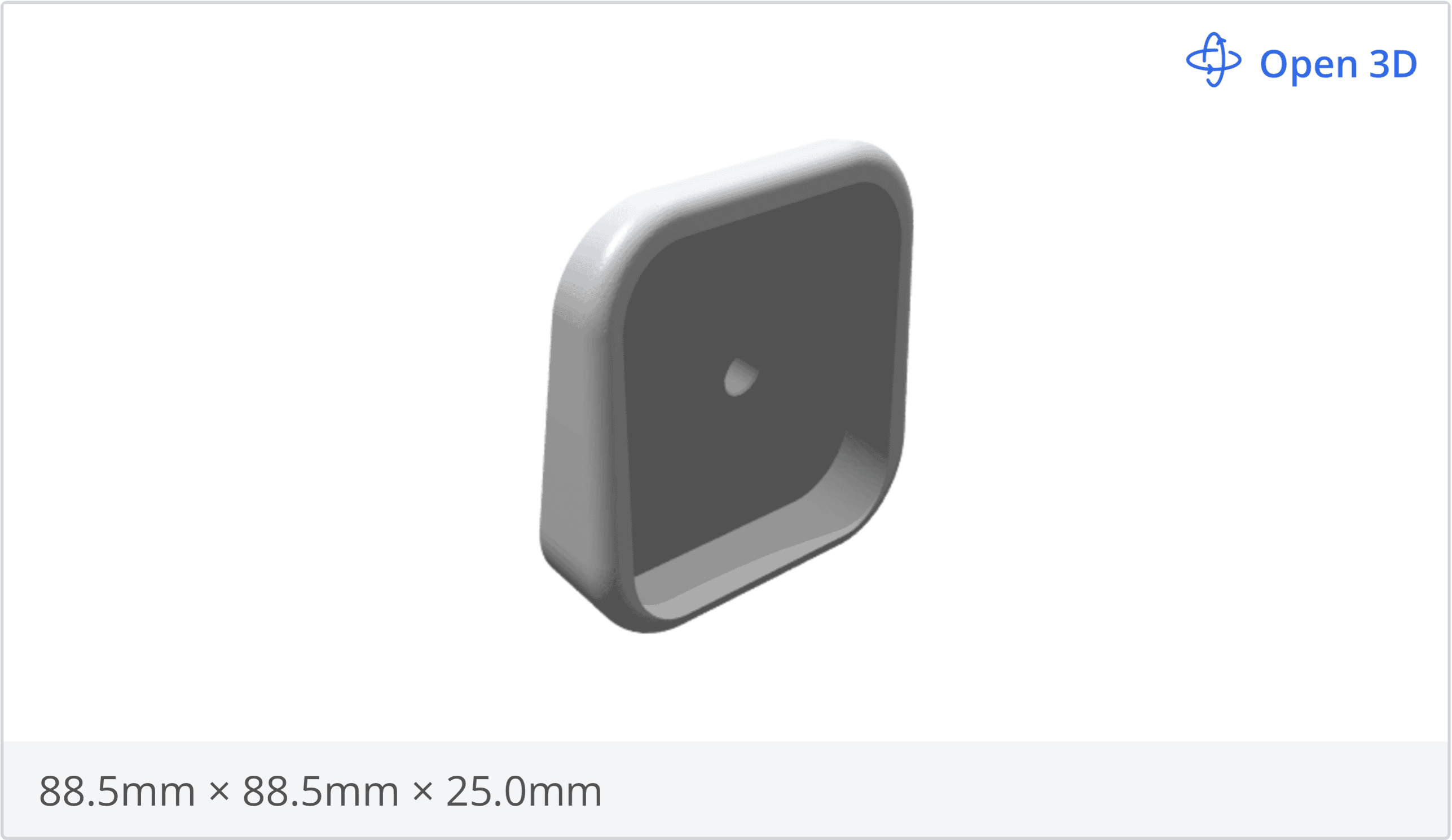
Using a part design (see CAD file) as a test model, we evaluated the pricing for MJF and SLS 3D printing technologies with PA 12 (grey) using our Xometry Instant Quoting Engine®. The results indicated that SLS is approximately 20% more expensive for single-unit production, but SLS and MJF have similar costs when scaled up. However, MJF becomes more cost-effective at larger scales.

| Technology & Material | Unit price for 10 units (€) | Unit price for 100 units (€) |
| MJF PA 12 | 39.77 | 21.13 |
| SLS PA 12 | 38.96 | 33.01 |
Prices are based on Xometry Instant Quoting Engine® as of May 2024.
Should I Design Differently for MJF vs SLS?
The design rules for MJF and SLS technologies are nearly identical. What should be considered, though, is the variation in standard tolerances. Both processes have a tolerance of ±0.3% for parts bigger than 100 mm, but MJF offers a slightly tighter tolerance for parts below 100 mm (±0.2 mm vs. ±0.3 mm for SLS).
Can MJF and SLS Be Used Interchangeably?
Although, the technologies have differences, in many applications they can be used interchangeably when the requirements for mechanical properties, part complexity, and material properties overlap. Here are some general applications where both technologies can be suitable:
- Functional testing parts: Both technologies can produce sufficient mechanical strength and durability to withstand functional testing of parts such as brackets, clips, and housings in PA 11, PA 12, or PA 12 glass-filled for enhanced rigidity.
- End-use production parts: MJF and SLS can produce strong and durable parts like connectors, gears, or housings for electronic devices in PA 12 and PA 12 glass-filled.
- Elastomeric parts: Both techniques can process TPU, a flexible and durable material, making them suitable for producing parts such as gaskets, seals, and flexible joints, that require elasticity and resilience.
How to Choose the Right 3D Printing Technology
In many basic applications, both SLS and MJF help get parts with comparable mechanical and surface qualities. At the same time, there are more demanding applications that could include finer resolutions, specific material requirements, and so on, where you could prefer one technology over the other.
The table below compares the key decision-making factors when choosing between SLS and MJF:
| Property | SLS | MJF |
| Processing time | Similar printing time to MJF, but the parts require longer cooling after printing | Similar printing time, but faster cooling thanks to dedicated post-processing stations |
| Build area | Can produce parts up to 550 x 550 x 750 mm | Can produce parts as large as 380 x 284 x 380 mm |
| Materials | Can print several materials, including PA 11, PA 12, PA 12 Glass-filled, Alumide, PA 2241 FR, PA 11, and PA 12 in food grade, PP, and TPU | Can currently print only PA 11, PA 12, PA 12 Glass-filled, PP, and TPU |
| Finishing | As printed parts produced have a grainy surface finish. There are various finishing options available. | As printed parts produced have a grainy surface finish. There are various finishing options available. |
| Cost | SLS and MJF have similar printing costs when scaled up, but SLS tend to be more expensive for single-unit production. However, the cost depends on various factors and should be evaluated on a case-by-case basis. | |
| Applications | Ideal for creating prototypes and functional parts like enclosures, mechanical fittings, housings for electronic devices, and organic/artistic designs. | Ideal for creating prototypes and functional parts in low to medium production volumes, including enclosures, sports equipment, industrial products, integrations, and drone components. |

Get MJF and SLS Parts at Xometry
Xometry offers SLS 3D printing and MJF 3D printing services with a large selection of materials and surface finish options for your production needs. With our Xometry Instant Quoting Engine®, you can easily compare and choose the best technology for your specific requirements. Simply upload your CAD file to get an instant quote with pricing and lead times.
Xometry also offers DFM feedback and consultancy services for corporate customers with our experienced engineers to help you choose the most suitable 3D printing option for your project.


Comment(3)