 Europe
  Türkiye


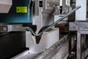
Bending is one of the most commonly used processes when forming sheet metal parts. It involves securing a flat sheet with a die or clamp and applying enough force to exceed the material’s yield strength, causing plastic deformation. The operation changes the part’s geometry—typically into V-shapes, U-shapes, or channels—without altering the sheet’s volume.
This guide offers engineers and designers a comprehensive overview of best practices, including how to select bending techniques, optimize part design, and ensure manufacturability through proper tolerances, features, radii, and compensation strategies.

Sheet Metal Bending Techniques
Sheet metal bending is not a one-size-fits-all process. Each method—such as air bending, bottoming, coining, or roll bending—has unique implications for accuracy, springback, tooling needs, and cost. Understanding the practical trade-offs allows engineers to make better DfM (Design for Manufacturing) decisions at the design stage.
The table below compares common bending methods based on practical design tips:
| Bending Method | Angle Accuracy | Springback | Practical Design Tips | Material Thickness Range | Limitations |
| Air Bending: Punch presses sheet partially into V-die without bottoming out | Moderate (~±1°) | High | Design with generous internal radii; anticipate large springback | 0.5–10 mm | Less accurate angle control; springback varies by material |
| Bottoming: Punch presses fully into V-die, defined bend | High (~±0.5°) | Low to Medium | Use matching punch and die angle; minimal springback means tighter tolerances | 0.5–12 mm | Tooling changes required for different angles |
| Coining: Punch compresses material, causing slight thinning | Very High (~±0.2°) | Minimal (~0%) | Ideal for complex bends and high-repeatability parts | < 6 mm | High tool wear; unsuitable for thicker materials |
| V-Bending: Forms sheet into V-shape using punch and die set | Moderate (~±1°) | Medium | General-purpose; use with consistent radii; match die opening to material thickness | 0.5–10 mm | Risk of cracking on sharp angles in brittle materials |
| U-Bending: Creates channel-shaped bend with U-shaped tooling | Moderate | Medium to High | Maintain consistent U-profile depth; avoid thin flanges near open ends | 1–10 mm | Angle precision is lower; prone to deformation in small flanges |
| Rotary Bending: Sheet rotates around pivot point without scratching surface | High (~±0.5°) | Low | Ideal for surface-sensitive materials (e.g., aluminum, coated parts) | 0.5–4 mm | Limited to simple angles; specialized tooling cost |
| Roll Bending: Forms sheet into large-radius curves through rollers | Low (±2–3°) | High | Specify large radii clearly; minimum recommended radius ≥ 5× sheet thickness | > 1 mm | Not suitable for sharp bends; process takes longer; less predictable shape |
Key Material Behavior Concepts
K-Factor
The K-Factor is a design parameter used to estimate how much a sheet metal part will stretch during bending. It defines the ratio between the neutral axis and the total sheet thickness. While it’s primarily a manufacturing value, understanding its role allows designers to better anticipate dimensional changes after bending.
K factor varies based on material properties (ductility and strength), inside bend radius relative to sheet thickness, bending method, and tooling precision.
Recommendations for K Factor:
- Increase the K-factor for materials with higher ductility, such as copper and brass, to account for stretching.
- Soft materials and sharp bends tend to push the neutral axis closer to the inside surface, lowering the K-Factor.
- Use a larger K-factor if bending angles exceed 120° to compensate for material elongation.
- A K-Factor of 0.5 implies that the neutral axis lies halfway through the material.
The table below shows recommended K-factors for the most common sheet metal materials and bending techniques.
Recommended K-Factors by Material and Bending Technique
| Radius Range | Aluminium 5082 | Aluminium 6061 | Aluminium 7075 | Stainless Steel 304 | Stainless Steel 316L | Steel S235/S355/DC01 |
| Air Bending | ||||||
| R ≤ T | 0.36 | 0.38 | 0.40 | 0.42 | 0.43 | 0.45 |
| T < R ≤ 3T | 0.40 | 0.42 | 0.44 | 0.46 | 0.47 | 0.48 |
| R > 3T | 0.50 | 0.50 | 0.50 | 0.50 | 0.50 | 0.50 |
| Bottom Bending | ||||||
| R ≤ T | 0.44 | 0.45 | 0.46 | 0.46 | 0.47 | 0.48 |
| T < R ≤ 3T | 0.47 | 0.48 | 0.49 | 0.48 | 0.49 | 0.50 |
| R > 3T | 0.50 | 0.50 | 0.50 | 0.50 | 0.50 | 0.50 |
| Coin Bending | ||||||
| R ≤ T | 0.41 | 0.43 | 0.45 | 0.44 | 0.45 | 0.46 |
| T < R ≤ 3T | 0.46 | 0.47 | 0.48 | 0.47 | 0.48 | 0.49 |
| R > 3T | 0.50 | 0.50 | 0.50 | 0.50 | 0.50 | 0.50 |
R: Inside bend radius, T: Material thickness
Springback & Compensation Strategies
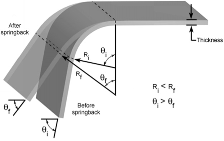
Sheet metal often tries to regain its original shape when the bending or punching force is released. This affects the dimensional accuracy of the parts and should be compensated for during the design. Springback effects depend on the material properties and bend radius.
Design-Focused Strategies to Compensate Springback
- Overbend the part slightly to match the intended final geometry.
- Avoid sharp bends in materials with high springback (e.g. 7075 Aluminium).
- Increase bend radius for ductile metals like copper to minimize stress concentration.
- Materials like stainless steel and aluminum require larger bend radii to reduce springback.
- Use lower-yield materials when tight angle tolerances are required.
Springback Compensation Formula
An approximate formula to estimate springback angle (Δθ):
Δθ = (K x R) / T
Where:
- Δθ = Springback angle (degrees)
- K = Material constant (between 0.8–2.0, higher for stronger materials)
- R = Inside bend radius
- T = Material thickness
Springback Behavior by Material
| Material | Springback Tendency | Design Notes |
| Aluminum 5082 | Low to Medium | Good ductility, low risk |
| Aluminum 6061 | Medium | Heat-treated alloys exhibit more springback |
| Aluminum 7075 | High | Hard alloy, requires aggressive overbending |
| Stainless Steel 304 | Medium | Elastic recovery must be factored in |
| Stainless Steel 316L | Medium to High | Overbending angle needed for accurate result |
| Mild Steel (S235/S355) | Low to Medium | Predictable behavior, low variance |
Bend Allowance and Bend Deduction
Accurate flat pattern design depends on understanding how sheet metal behaves during bending. Two key values help calculate precise unfolded lengths:
Bend Allowance (BA)
Bend Allowance is the arc length of the bend as measured along the neutral axis. It quantifies the material that will be “used up” in the bend.
Bend Allowance Formula:
BA = A × (π / 180) × (R + K × T)
Where:
- A = Bend angle (in degrees)
- R = Inside bend radius
- T = Sheet thickness
- K = K-Factor
Bend Deduction (BD)
Bend Deduction is the amount subtracted from the total length of the flanges to get the correct flat pattern.
Bend Deduction Formula:
BD = L1 + L2 − (BA + inside bend)
Where:
- L = Flange length
- BA = Bend Allowance
Design Tips:
- For most 90° bends, use bend tables for standard materials if formulas are too complex.
- When bending high-strength alloys (e.g., 7075, 316L), expect larger BD due to springback and stress accumulation.
- Always align grain direction perpendicular to the bend line to prevent cracking in aluminum and brittle steels.
Design Rules for Bending
To ensure a hitch-free bend and to avoid deformation, the following tips and guidelines are vital when designing.
Quick Reference Design Table for Bending
| Design Consideration | Minimum or Recommended Value / Guideline |
| Wall Thickness | Maintain uniform thickness throughout the part; avoid abrupt transitions |
| Bend Radius | Internal radius ≥ 1× material thickness (T); larger for brittle materials |
| Distance Between Bends | ≥ 3× T; increase spacing for thick materials or tight geometries |
| Relief Cuts & Notches | Width ≥ T; Length ≥ Bend Radius + 0.5× T, Notch spacing ≥ 3.2 mm |
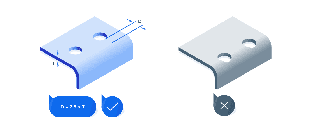
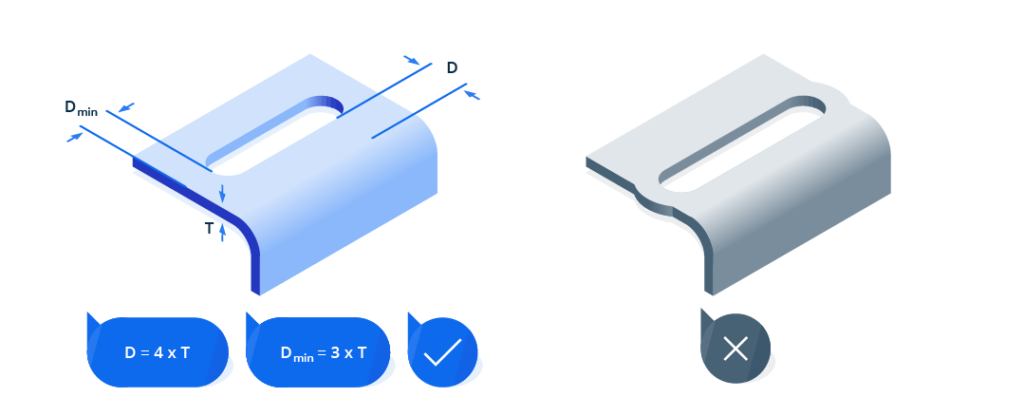
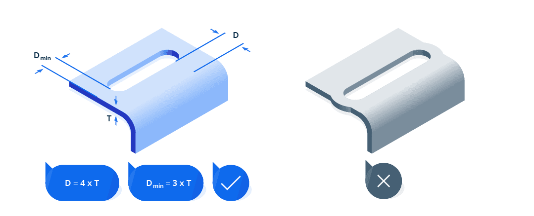
| Holes / Cutouts Near Bends | Holes: ≥ 2.5× T from bend line; Slots: ≥ 4× T from bend line |
| Countersinks | From bend: ≥ 3× T; From edge: ≥ 4× T; Depth ≤ 0.6× T |
| Curls | Outer Radius ≥ 2× T; Hole clearance ≥ Curl Radius + T; Bend clearance ≥ 6× T + Curl Radius |
| Hems | Flange Length ≥ 4× T; Avoid closed hems if painted/coated SS or Aluminum is used |
| Minimum Flange Length | ≥ 4× T (check press brake tooling limits) |
| Minimum Leg Length | ≥ 4× T (≥ 6× T for high-strength or thick materials) |
| Alignment Features | Use tabs, slots, and pins; avoid stacking multiple features near one bend |
| Z-Bend Height | Total Height ≥ 2.5× T; Flange ≥ 1.5× T; Spacing between Z-bends ≥ 3× T |
| U-Profiles | Internal Width ≥ 4× T; Flange Height ≥ 2× T; Inner Radius ≥ 1.5× T |
| Component Size Limits | ≤ 3000 × 1500 mm (Steel/Aluminum); ≤ 2500 × 1250 mm (Stainless Steel) |
Keep Wall Thickness Uniform
The thickness of the sheet metal directly impacts the bend radius and other critical bending parameters, such as V-opening, bending force, and flange length. Understanding this relationship is crucial for ensuring the quality and durability of the bend.
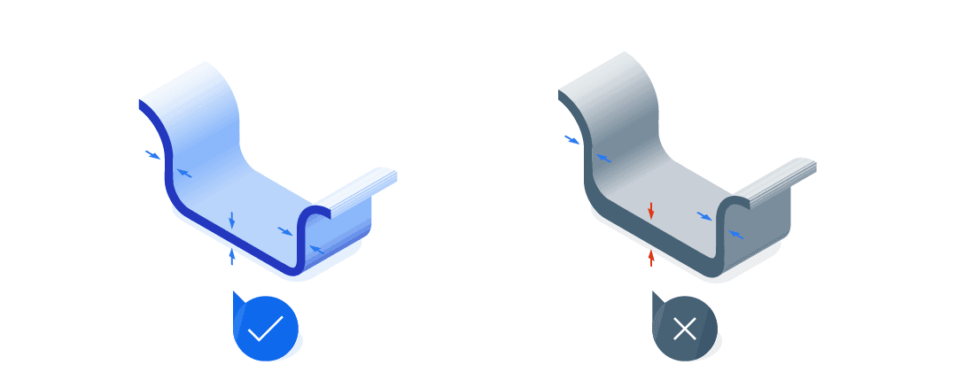
Maintaining uniform wall thickness ensures consistent bending behavior and prevents issues such as deformation, warping, or cracking.
Design Tips:
- Maintain consistent thickness across the part.
- Avoid abrupt thickness changes or ribs near bends.
- If thickness changes are necessary, design gradual transitions (at least 3× sheet thickness) or use chamfers to reduce stress concentrations.

Minimum Bendable Lengths: Legs and Flanges
The minimum length of a bendable leg or flange is defined by the material thickness, bending method, and tooling geometry. Short legs that are too small relative to thickness may not form properly or may result in inaccurate angles and warping.
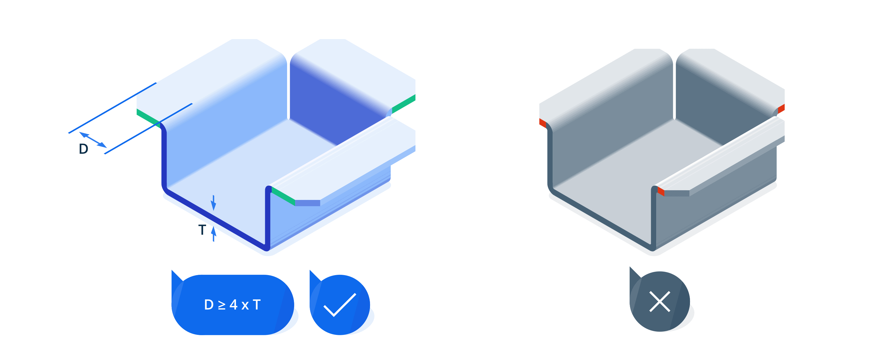
Design Tips:
- For air bending, leg/flange length should be ≥ 4 × T
- For bottoming, increase to ≥ 6 × T
- Avoid placing holes, notches, or edges too close to these short bends.
- Short flanges may require special forming tools or secondary operations.
- In Z-bends, both legs must meet this minimum to avoid tool collisions.
Exact values depend on material type, bend angle, and press tooling. Use the following tables as practical minimum leg length values for typical tooling configurations.
Minimum Leg Length – Steel and Aluminum
| Material Thickness (T) | Min. Leg Length ≥ (90°) | Min. Leg Length ≥ (<90°) |
| 1.0 mm | 6 mm | 10 mm |
| 1.5 mm | 8 mm | 10.5 mm |
| 2.0 mm | 9.5 mm | 13 mm |
| 2.5 mm | 12 mm | 15.5 mm |
| 3.0 mm | 12.5 mm | 22 mm |
| 4.0 mm | 18 mm | 22.5 mm |
| 5.0 mm | 23 mm | 23 mm |
| 6.0 mm | 30 mm | 30 mm |
| 8.0 mm | 43 mm | 43 mm |
* These values apply to air bending with standard V-dies. For coining or bottom bending, shorter legs may be possible.
Minimum Leg Length – Stainless Steel
| Material Thickness (T) | Min. Leg Length ≥ x (90°) | Min. Leg Length ≥ x (<90°) |
| 1.0 mm | 6 mm | 10 mm |
| 1.5 mm | 8 mm | 10.5 mm |
| 2.0 mm | 9.5 mm | 13 mm |
| 2.5 mm | 12 mm | 15.5 mm |
| 3.0 mm | 15 mm | 22 mm |
| 4.0 mm | 18 mm | 22.6 mm |
| 5.0 mm | 29.5 mm | 29.5 mm |
| 6.0 mm | 42 mm | 42 mm |
| 8.0 mm | 43 mm | 43 mm |
* These values apply to air bending with standard V-dies. For coining or bottom bending, shorter legs may be possible.
Bends: Radius & Orientation
The bend radius plays a critical role in ensuring structural integrity and avoiding cracks. A too-small radius can overstress the material, especially with thicker or less ductile metals (316L or 7075). Larger radii improve formability and reduce springback, especially for materials like stainless steel and aluminum.
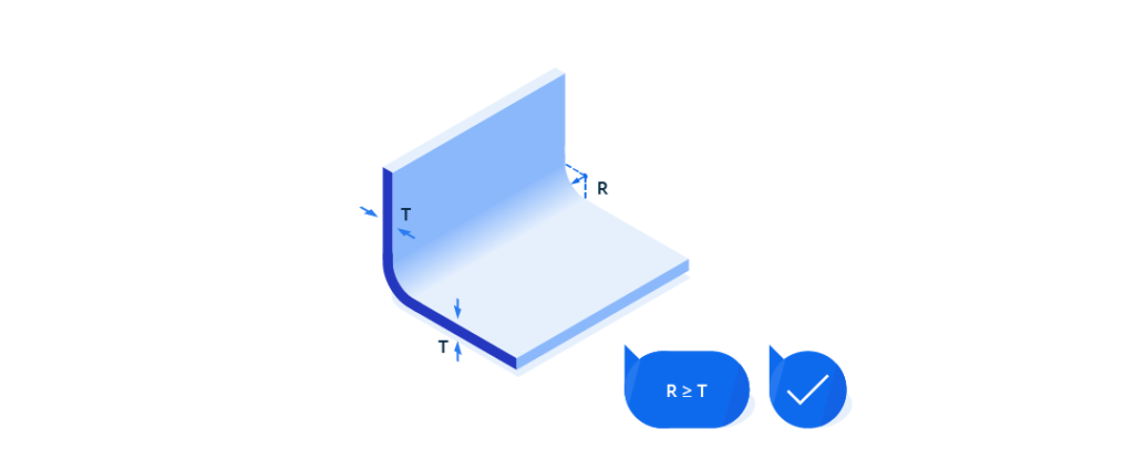


Design Tips:
- Use a minimum internal radius of ≥ 1 × T for most ductile metals.
- For harder materials, increase to ≥ 1.5 × T to prevent cracking.
- Avoid specifying sharp or zero-radius bends. These concentrate stress and are likely to cause cracking—particularly in stainless steels.
- If a sharp profile is required visually, use post-machining or chamfering rather than tight bending.
- Maintain consistent radii across multi-bend parts to simplify tooling and reduce cost.
- Check tooling limitations if designing very tight bends or complex geometries.
Interactive Air Bend Force Chart
| V, mm i | 6 | 8 | 10 | 12 | 16 | 20 | 25 | 32 | 40 | 50 | 63 | 80 | 100 | 125 | 160 | 200 | 250 | 320 | 400 | 500 | ||
|---|---|---|---|---|---|---|---|---|---|---|---|---|---|---|---|---|---|---|---|---|---|---|
| b, mm i | 4 | 5.5 | 7 | 8.5 | 11 | 14 | 17.5 | 22 | 28 | 35 | 45 | 55 | 71 | 89 | 113 | 140 | 175 | 226 | 280 | 350 | ||
| ir, mm i | 1 | 1.3 | 1.6 | 2 | 2.6 | 3.3 | 4 | 5 | 6.5 | 8 | 10 | 13 | 16 | 20 | 26 | 33 | 41 | 53 | 65 | 83 | ||
| t, mm i | 0.5 | 4 | 4.4 | F, t/m i | ||||||||||||||||||
| 0.8 | 4 | 5.5 | 7 | |||||||||||||||||||
| 1 | 11 | 8 | 7 | 6 | ||||||||||||||||||
| 1.2 | 16 | 12 | 10 | 8 | 6 | |||||||||||||||||
| 1.5 | 17 | 15 | 13 | 9 | 8 | |||||||||||||||||
| 2 | 27 | 22 | 17 | 13 | 11 | |||||||||||||||||
| 2.5 | 35 | 26 | 21 | 17 | 13 | |||||||||||||||||
| 3 | 38 | 30 | 24 | 19 | 15 | |||||||||||||||||
| 4 | 54 | 42 | 34 | 27 | 21 | |||||||||||||||||
| 5 | 67 | 52 | 42 | 33 | 26 | |||||||||||||||||
| 6 | 75 | 60 | 48 | 38 | 30 | |||||||||||||||||
| 8 | 107 | 85 | 68 | 53 | 43 | |||||||||||||||||
| 10 | 134 | 105 | 85 | 67 | 53 | |||||||||||||||||
| 12 | 153 | 120 | 95 | 78 | 60 | |||||||||||||||||
| 15 | 188 | 150 | 120 | 95 | 75 | |||||||||||||||||
| 20 | 215 | 170 | 135 | 108 | 85 | |||||||||||||||||
| 25 | 265 | 210 | 170 | 130 | 105 | |||||||||||||||||
| 30 | 300 | 240 | 190 | 150 | 120 |
Sheet Metal Bending Radius Calculator
| 4 | 17.5 | 25 | 67 |
| 5 | 22 | 32 | 52 |
| 6.5 | 28 | 40 | 42 |
| 8 | 35 | 50 | 33 |
| 10 | 45 | 63 | 26 |
| ir, mm | b, mm | V, mm | F, t/m |
- 0.5
- 0.8
- 1
- 1.2
- 1.5
- 2
- 2.5
- 3
- 4
- 5
- 6
- 8
- 10
- 12
- 15
- 20
- 25
- 30

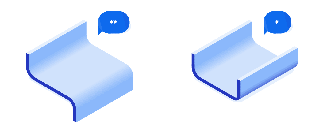
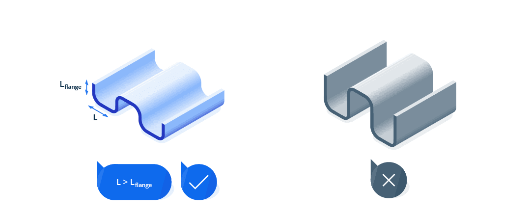
Bends: Placing Bends Next to Each Other
You should avoid successive bends except where absolutely necessary. A common problem for successive bends is the difficulty of fitting the bent parts on the die. However, when unavoidable, the intermediate part should be longer than the flanges.

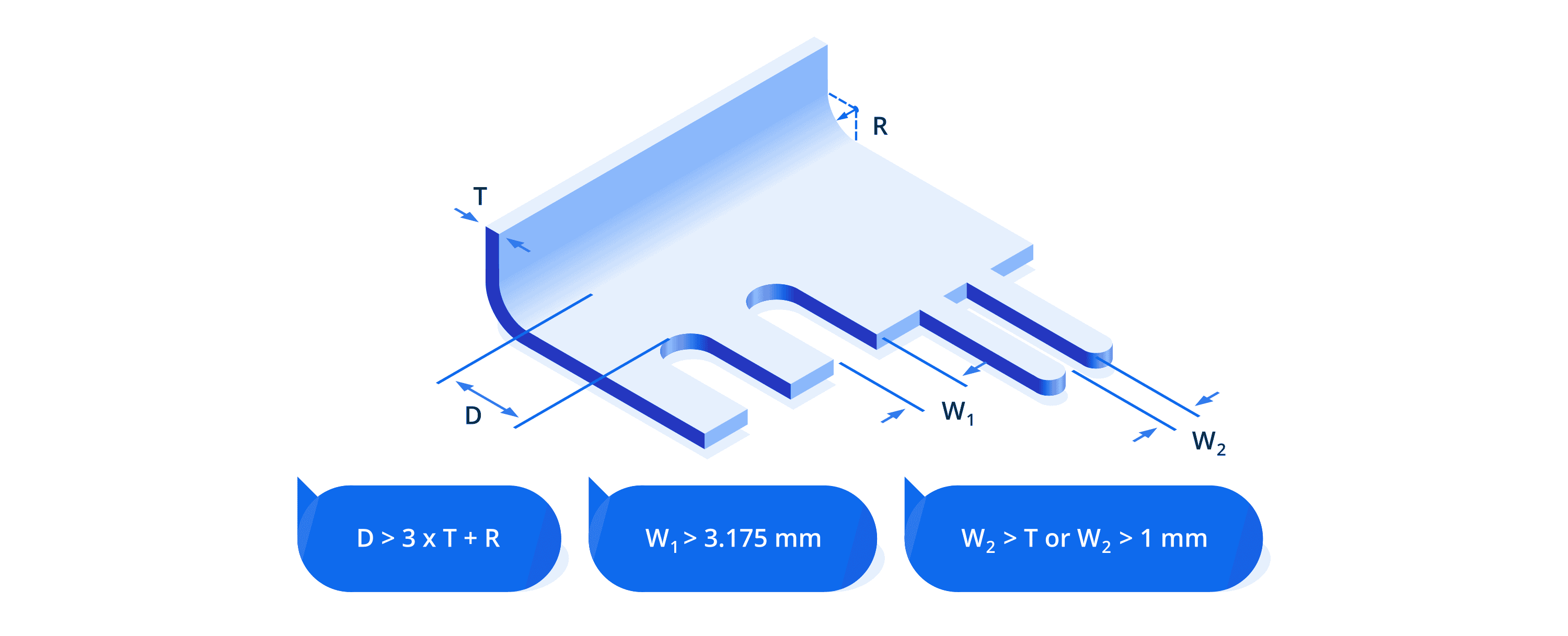
Features Around Bends: Holes, Notches & Reliefs
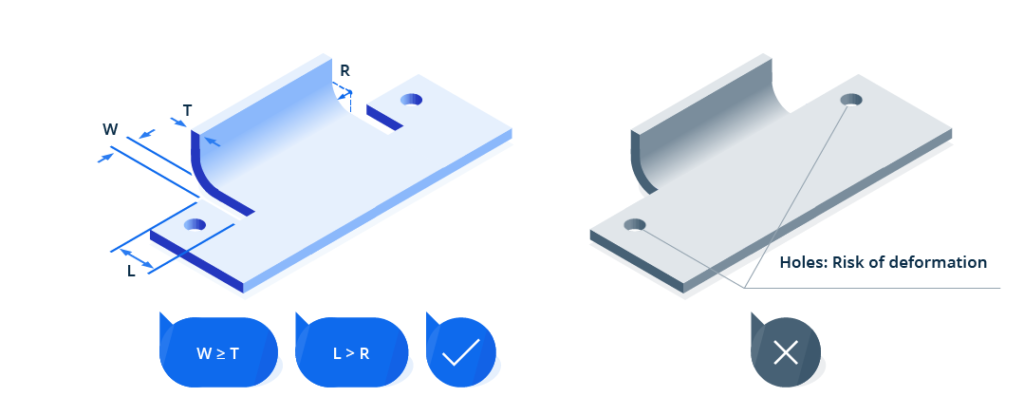
Incorrect placement of features near bend lines can lead to deformation, stress accumulation, or tooling complications. This includes holes, slots, extrusions, and bend reliefs. Thoughtful spacing and geometry choices are essential for preserving part quality during forming.

Design Tips:
- Avoid placing features too close to bends. Distortion or tearing may occur during forming.
- Use obround or tear-drop holes instead of round holes near bends to minimize stress.
- Add bend reliefs if the bend is closer than 2 × material thickness from any edge or cutout.
- Round all relief corners to prevent crack initiation.
- Add slot-style or tear-drop reliefs for thin sheets to reduce wrinkling.
- Distribute features across the part rather than clustering them near bends.
- Account for laser kerf and edge burn when sizing reliefs or notches.

| Feature Type | Min. Distance from Bend | Min. Distance from Edge | Notes |
| Hole (Standard) | ≥ 2.5 × T | ≥ 1.5 × T | Round shapes preferred |
| Slot (Radiused Ends) | ≥ 4 × T | ≥ 2 × T | Use for stress relief near bends |
| Extruded Hole | ≥ 3 × T | ≥ 2.5 × T | Reinforce or move away from bend line |
| Obround/Tear-Drop | ≥ 2 × T | ≥ 1.5 × T | Good for tight spacing around bends |
| Bend Relief Width | ≥ 1 × T | — | Use rectangular or tear-drop shape reliefs |
| Bend Relief Length | ≥ R + 0.5 × T | — | Extend slightly past the bend line |
| Notch-to-Bend Distance | ≥ 3 × T + R | — | Prevent stress at transitions |
| Notch Spacing | ≥ 3.2 mm | — | Maintain between adjacent features |

Use Standard Bending Angles
Non-standard angles require specialized tooling, increasing cost and complexity.
Design Tips:
- Prefer 30°, 45°, 60°, and 90° angles where possible.
- Avoid angles sharper than 90° in high-strength materials to minimize cracking.
- Reuse same-angle features across parts when possible to reduce die changes and machining time.
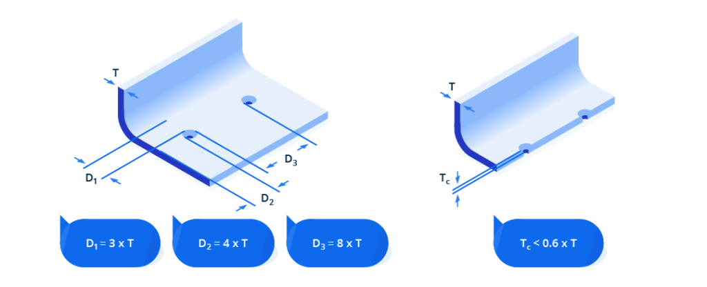
Countersinks
Countersinks are used to recess flat-head fasteners into sheet metal. When placed too close to bends or edges, they can cause deformation, misalignment, or cracking — especially in thin or hard materials.
Design Tips
- Place countersinks ≥ 3 × T away from bend lines.
- Keep ≥ 4 × T distance from sheet edges.
- Leave ≥ 8 × T between adjacent countersinks.
- Limit countersink depth to ≤ 0.6 × T
- Use a standard angle of 82° (US) or 90° (metric) based on screw specification.

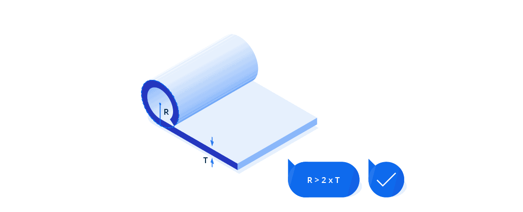
Curls
Curls are rolled edges that improve part safety by removing sharp edges and increasing structural stiffness. They’re commonly used in enclosures, covers, or parts handled by operators.
Design Tips:
- Minimum Outside Radius: ≥ 2 × T
- Hole Clearance (from Curl): ≥ (Curl radius + T)
- Distance from Other Bends: ≥ 6 × T + curl radius
- Curl Opening: For open curls, maintain at least 1.5 × T

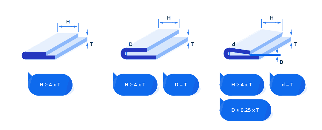
Hems
Hems are folded edges used to reinforce part edges or eliminate sharp borders. They can be open, teardrop, or closed, depending on use case. Open and teardrop hems are easier to manufacture, while closed hems may present paint or material compatibility issues.
Design Tips:
- For hinge-like functions, prefer open or teardrop hems over closed ones.
- Avoid closed hems in designs with tight tolerance or complex coatings.
- Be aware that closed hems may increase springback risk due to their sharp forming geometry.
| Hem Type | Hem Inside Diameter | Flange Length Recommendation |
| Open | ≥ 1 × T | ≥ 4 × T |
| Teardrop | = 1 × T | ≥ 4 × T |
| Closed | ≤ 1 × T | ≥ 4 × T |

Bending Limitations by Geometry
Respect Minimum Z-Bend Heights
A Z-bend involves two parallel bends in opposite directions, creating a Z-shaped profile.
Z-bends (offset bends) require a minimum vertical step height to accommodate the lower tool during bending. It depends on factors like material thickness, die slot width, and the specific bending process used and avoids tooling collisions or material distortion.
Design Tips:
- For manufacturability, minimum Z-bend height should be ≥ 2.5× sheet thickness (T), ensuring sufficient tool clearance and structural integrity.
- Maintain flange length ≥ 1.5 × T to ensure proper tool engagement.
- Avoid tight Z-bends in high-strength alloys like stainless steel 316L or aluminum 7075.
- Consider increasing step height beyond minimums for tight tolerances or cosmetic surfaces.
- Use the material-specific guidelines in the reference tables below to determine safe step heights.
Z-Bend Step Height – Steel & Aluminum
| Material Thickness (T) | Step Height ≥ X (≥ 90°) | Step Height ≥ X (< 90°) |
| 1.0 mm | 8.5 mm | 18.5 mm |
| 1.5 mm | 10.5 mm | 19.5 mm |
| 2.0 mm | 14 mm | 20.5 mm |
| 2.5 mm | 19 mm | 26 mm |
| 3.0 mm | 20 mm | 35 mm |
| 4.0 mm | 26 mm | 35.5 mm |
| 5.0 mm | 34 mm | 34 mm |
| 6.0 mm | 42.5 mm | 42.5 mm |
| 8.0 mm | 61 mm | 61 mm |
Z-Bend Step Height – Stainless Steel
| Material Thickness (T) | Step Height ≥ X (≥ 90°) | Step Height ≥ X (< 90°) |
| 1.0 | 9.0 | 19.0 |
| 1.5 | 11.0 | 20.0 |
| 2.0 | 14.5 | 21.5 |
| 2.5 | 20.0 | 26.5 |
| 3.0 | 25.0 | 36.0 |
| 4.0 | 27.5 | 38.0 |
| 5.0 | 43.5 | 44.0 |
| 6.0 | 63.5 | 63.5 |
Optimize U-Profiles for Manufacturability
U-profiles (also called channels) are common in brackets, enclosures, and structural parts. However, overly tight or deep profiles can cause forming challenges, such as wrinkling, springback, or tool interference.
Design Tips:
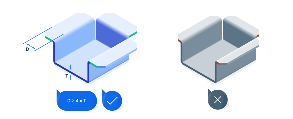
- Internal width ≥ 4 × T to allow tool access and prevent wrinkling.
- Flange height ≥ 2 × T to maintain part rigidity and avoid deformation.
- Inner bend radius ≥ 1.5 × T to reduce cracking risk, especially in high-strength alloys.
- Add relief notches at flange-base intersections to reduce stress concentration.
- For deep or long U-channels:
- Break bending into multiple operations.
- Add internal ribs or gussets to support long flanges.
- Consider shortening legs or widening the base for formability.
Tolerancing and Fit Strategy
This next part of the article highlights practical guidelines to determine optimal component sizing, precise tolerances, and fit strategies, critical to successful fabrication and assembly.
Consider Component Size Limitations
Sheet metal components must stay within machine and material constraints. Oversized parts may warp or distort during handling, while undersized parts may be difficult to bend accurately or hold securely in tooling.
Design Tips:
- Keep part sizes within standard sheet formats to reduce waste and cost.
- Use stiffening flanges or ribs to minimize distortion in large panels.
- Respect standard machine limits:
- Max size: ~3000 × 1500 mm
- Min size (by thickness):
- Up to 5 mm: ≥ 10 × 10 mm
- 6–15 mm: ≥ 20 × 20 mm
- 16–20 mm: ≥ 25 × 25 mm
- Up to 5 mm: ≥ 10 × 10 mm
- Max size: ~3000 × 1500 mm
Tolerances and Fit Strategies
Precise tolerancing is essential to ensure reliable manufacturing, especially when dealing with springback, tooling variation, or multi-step forming.
Tolerance Recommendations:
- General tolerance recommendation is ±0.5 mm for non-critical dimensions. Use ±0.25 mm for features that require tighter fit such as flange heights or hole positioning.
- Apply tighter tolerances only where essential—e.g., hole alignment, mating interfaces.
- Use GD&T (e.g., true position) instead of chained dimensions for multi-bend parts.
- Allow tolerance for welding, coating, or post-machining steps.
Fit Optimization Tips
- Prefer clearance fits (0.1–0.3 mm typical) for easy assembly.
- Add alignment aids like tabs, notches, or slots to control part position.
- Design integrated flanges/brackets to reduce part count and assembly steps.
- Leave clearance for fastening tools (screwdrivers, rivet guns, weld tips).
General Tolerancing Guidelines
| Feature | Recommended Tolerance | Notes |
| Bend angle (air bending) | ±1° | Bottoming: ±0.5°, Coining: ±0.25° |
| Flat pattern dimensions | ±0.25 mm | For non-critical features |
| Hole diameters (laser cut) | ±0.1 mm | ±0.2 mm for punching |
| Hole positioning | ±0.2–0.3 mm | Tighter if alignment is critical |
| Flange heights | ±0.25 mm | Depends on springback and bending method |
| Tab-to-tab distance | ≥ 1 mm or 1 × T | Whichever is greater |
| Notch-to-notch distance | ≥ 3.175 mm | From edge or bend |
The Final Fold: Putting DFM into Practice
Whether you’re prototyping a simple bracket or scaling production for aerospace components, success in sheet metal bending starts with informed design. This guide has walked through key principles — from bend radii and springback to flange design and tolerance planningReady to take your designs further? Connect with engineers on Xometry Pro Community to get feedback, swap techniques, or share your most clever workaround. Every smart design improves the next one.


Comment(1)