 Europe
  Türkiye

Choosing the appropriate CAD file format is the cornerstone of a seamless manufacturing process and the only way to avoid frustrations. Whether you’re designing parts for CNC machining, sheet metal fabrication, 3D printing, injection moulding, or any other manufacturing process, it’s crucial to get the CAD file format right from the start, as each technology has its own preferred formats.
Comparison Table: Best File Formats by Manufacturing Process
Different manufacturing processes require different CAD file formats to ensure smooth and accurate production. Here’s a breakdown of the preferred and alternative file formats for each major process, along with recommendations.
| Manufacturing Process | Preferred File Formats | Alternative File Formats | Recommendation |
| CNC Machining | STEP IGES X_T/X_B |
SLDPRT IPT PRT SAT 3DXML/CATPART PTC |
Use STEP for the best compatibility |
| Sheet Metal Fabrication | DXF DWG STEP |
IGES SLDPRT X_T/X_B SAT IPT 3DXML/CATPART PTC PRT |
Use DXF for laser cutting |
| 3D Printing | STL OBJ 3MF |
AMF | STL is the most common |
| Injection Molding | STEP | SLDPRT | STEP is the safest option |
Many of these file formats are used interchangeably for CNC machining, 3D printing, and sheet metal fabrication. However, characteristics of some CAD file formats make them recommended for only specific processes, as described in the following sections.
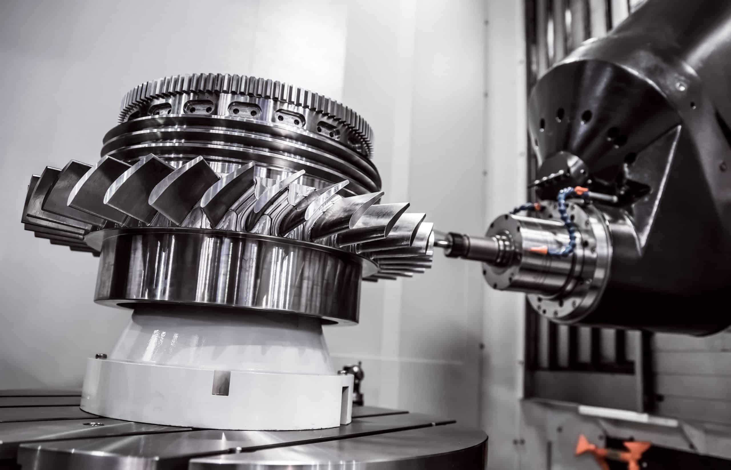
CAD Formats Used for CNC Machining
For CNC machining, a 3D model is converted directly from a 3D file into machine code. There are as many 3D file formats as 3D CAD modeling applications. This is because most CAD applications save files in a proprietary file format. The most popular file formats used in CNC machining are:
- SLDPRT (SOLIDWORKS)
- X_T | X_B (Parasolid)
- IPT (Autodesk Inventor)
- 3DXML | CATPART (Dassault Systems)
- PTC (PTC)
- PRT (Siemens)
- SAT (ACIS)
Additionally, standard non-proprietary file formats were created to ease collaboration and are compatible with the most popular CAD software. The two most popular ones are highlighted below:
- STEP: Also known as STP, this 3D file format was created by ISO (International Standards Organisation). It has the .stp or .step file extension and is widely accepted as a standard CAD file format.
- IGES: The IGES is an interchange file format created by the US Air Force. It is widely accepted and compatible with virtually all CAD software. IGES files have a .igs or .iges file extension.
The two standard non-proprietary file formats have become so popular that most CAD applications allow you to save your designs in these formats.
The table below summarises the different file formats for CNC manufacturing and their best use cases, the first one being the most recommended CAD file format for this process.
| File Format | Description | Best Use Case |
| STEP (.stp) | ISO standard file format; widely supported across CAD/CAM software | • Best for interoperability and exchanging CAD data because of their wide compatibility. • Retains solid geometry, making it ideal for exchanging 3D models between different systems. |
| IGES (.iges) | Older standard, but still used for compatibility between CAD systems | • Good for transferring wireframe and surface models. • Suited for designs that require less precise solid modeling, such as simpler parts, legacy systems. |
| SOLIDWORKS (.sldprt) | Native SOLIDWORKS file format | • Best for internal use or when working within SOLIDWORKS and not any external applications. |
| Parasolid (.x_t, .x_b) | Kernel format used by many CAD programs | • Useful for retaining geometric accuracy. • Suited for machining applications that require exact geometric data. |
| Autodesk Inventor (.ipt) | Native Autodesk Inventor format | • Best for Inventor users. • Needs to be exported as a STEP or Parasolid file before being used in CNC machining workflows. |
| CATPART (.3dxml, .catpart) | Dassault Systèmes native format (CATIA) | • Used in aerospace and automotive industries. • Ideal for complex, high-precision parts, but may need to be converted to STEP or another neutral format for CNC machining. |
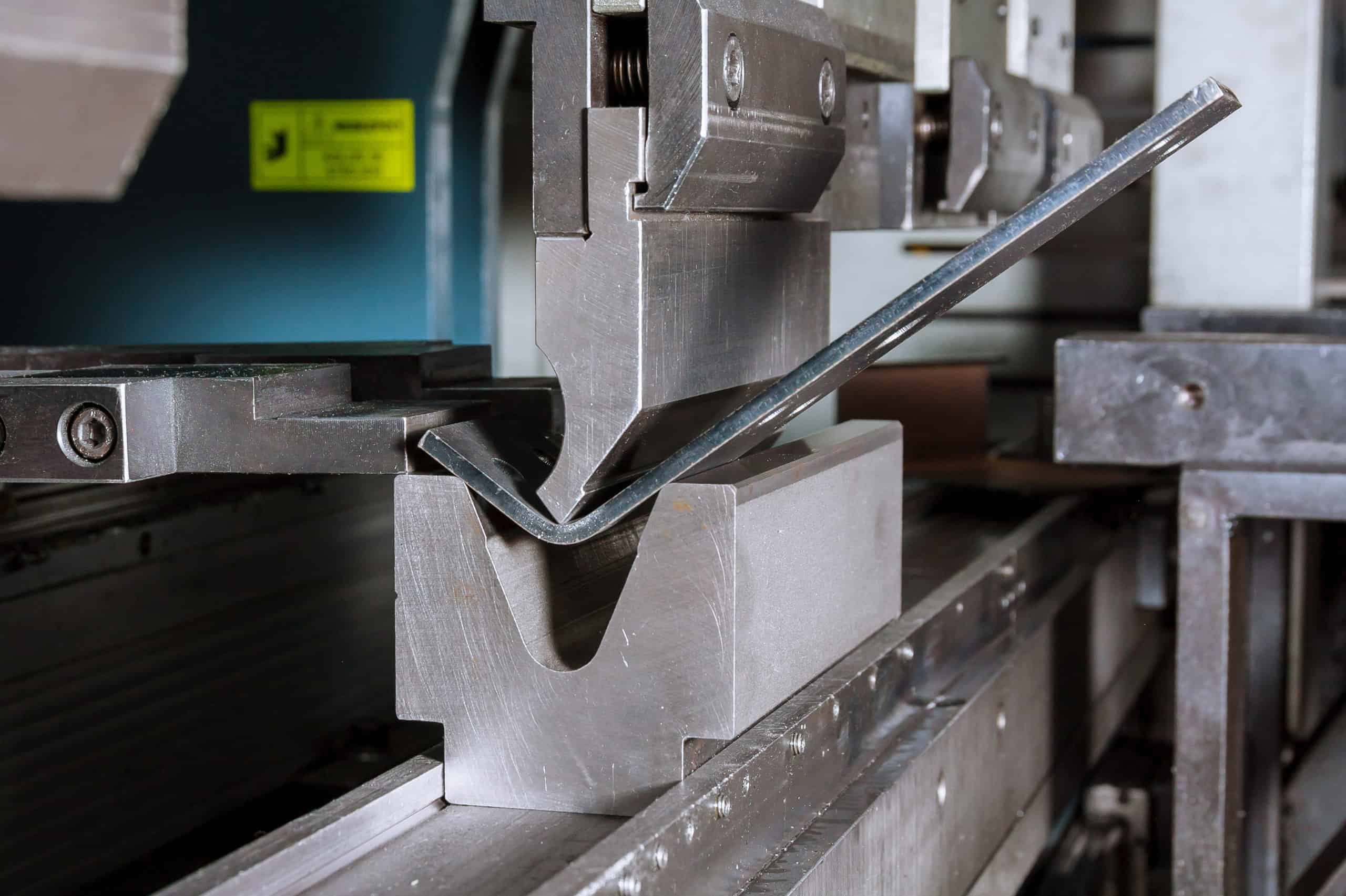
CAD Formats Used for Sheet Metal Fabrication
Sheet metal cutting processes are carried out using CNC devices. Files for this process are therefore prepared similarly. Ensure that bend lines and material thickness are clearly defined in the file before sending the CAD file to the manufacturer.
Possible CAD file formats for sheet metal cutting include:
- DWG
- SAT
- DXF
- IGES
- STEP
- SLDPRT
- X_T | X_B
- IPT
- 3DXML | CATPART
- PTC
- PRT
- SAT
The table below summarises the different file formats for sheet metal fabrication and their best use cases, the first one being the most recommended CAD file format for this process.
| File Format | Description | Best Use Case |
| DXF (.dxf) | 2D vector format for CNC cutting | • Best for laser, plasma, and waterjet cutting. • It’s the go-to for defining cut paths and ensuring accurate material processing because it supports precise curves, lines, and dimensions. |
| DWG (.dwg) | Native AutoCAD 2D/3D format | • Used for detailed 2D drawings, e.g. flat patterns, manufacturing blueprints, and annotations. • Ideal for comprehensive documentation and design revisions since it retains layer information. |
| STEP (.stp) | ISO standard file format; widely supported across CAD/CAM software | • Best for complete sheet metal part models or 3D sheet metal designs. • Facilitates smooth collaboration between different CAD platforms because of high compatibility with most sheet metal fabrication software. |
| IGES (.iges) | Older standard, but still used for compatibility between CAD systems | • Good for transferring 2D and 3D designs, but less precise than STEP for 3D data. • Commonly used for simpler parts and when compatibility with older systems is needed. |
| SOLIDWORKS (.sldprt) | Native SOLIDWORKS file format | • Best for internal use in SOLIDWORKS workflows. • Retains full parametric history, design features, and sheet metal-specific properties such as bend allowance. |
CAD Formats Used for 3D Printing
A model needs to be in a 3D printing file format before it can be prepared for 3D printing. 3D printing files can be obtained in two ways:
- By converting an existing 3D model into a 3D file format
- By creating a model and saving it directly in a 3D printing file format. To avoid print errors with these file formats, ensure the model is watertight (no gaps in the geometry).
There are four popular 3D printing file formats. They include the following:
- STL
- OBJ
- AMF
- 3MF
It is important to note that models in 3D printing file formats cannot generate CNC machine code. Hence, such models cannot be used with CNC machining or cutting processes. They are exclusively for 3D printing.
The table below summarises the different file formats for 3D printing and their best use cases, the first one being the most recommended CAD file format for this process.
| File Format | Description | Best Use Case | Limitations |
| STL (.stl) | Most common format; stores geometry as a mesh of triangles. Universally supported across 3D printing platforms. | • Best for general 3D printing applications, prototyping, and simple parts, e.g., basic mechanical components | • No support for color, texture, or detailed material properties |
| OBJ (.obj) | Supports texture, color, and material properties; allows for high-detail rendering. | • Best for multi-color and multi-material prints. • Ideal for detailed models requiring texture and color, e.g., character models in gaming, complex architectural designs. |
• Can be large and complex due to additional data. • May require managing multiple files (geometry, textures). |
| 3MF (.3mf) | More advanced format with additional metadata. Compact and efficient; supports advanced features like color, material, and complex geometries. | • Best for professional-grade 3D printing. • Ideal for modern, versatile applications, e.g., consumer products with detailed features, mixed-material objects. |
• Growing support but not yet as universal as STL; may require modern software. |
| AMF (.amf) | XML-based format for additive manufacturing. Supports multiple materials, colors, and textures; ideal for intricate designs. | • Alternative to STL with additional data storage. • Ideal for advanced applications needing detailed attributes, e.g., multi-material prototypes, complex color patterns. |
• Less supported by 3D printers and software. • More complex than STL. |
Apart from the four mentioned file formats for 3D printing, you can also use others, but these need to be converted to be used with the CNC machining or cutting process. They include the following:
- SLDPRT
- X_T | X_B
- IPT
- 3DXML | CATPART
- PTC
- PRT
- SAT
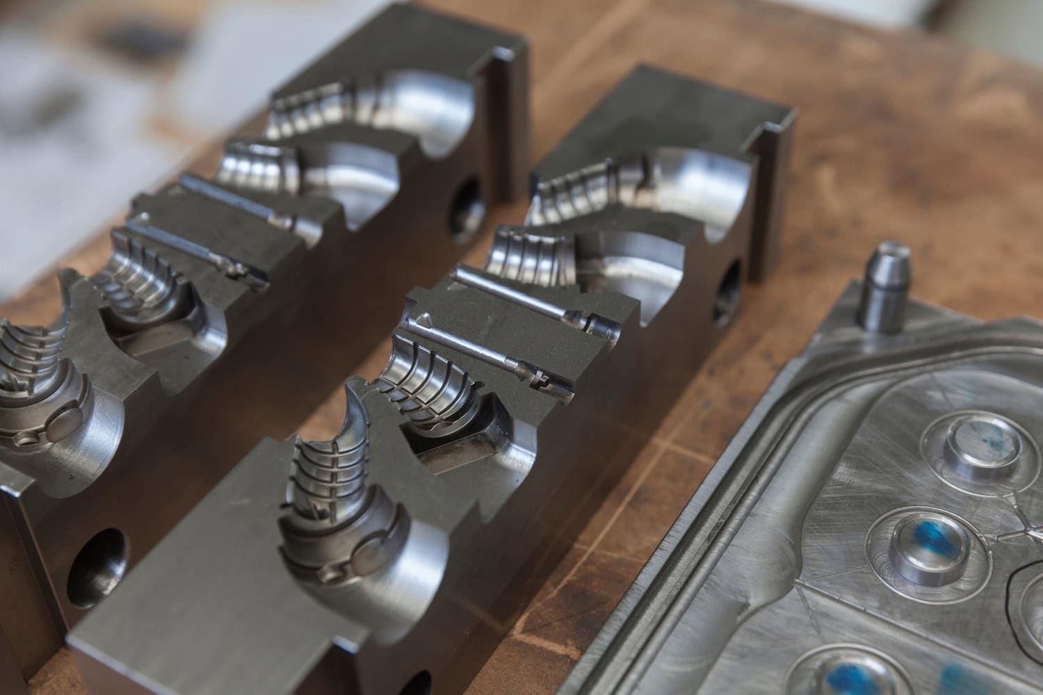
CAD Formats Used for Injection Moulding
When designing parts for injection moulding, selecting the appropriate CAD file format ensures accurate geometry transfer and efficient manufacturing. Appropriately choosing a file format prevents data loss and incompatibility issues with the machinery used. Manufacturers using injection moulding technology prefer STEP or Parasolid because of their high compatibility.
Different formats serve various purposes, from internal design iterations to cross-platform compatibility. Understanding them and their use cases helps streamline the transition from design to production. The most popular formats are the following:
- STEP
- SOLIDWORKS
The table below summarises the different file formats for injection moulding and their best use cases, the first one being the most recommended CAD file format for this process.
| File Format | Description | Best Use Case |
| STEP (.stp) | ISO standard file format; widely supported across CAD/CAM software | • Best for transferring designs across different CAD systems since it’s a neutral format, it preserves 3D geometry and is widely accepted by manufacturers. |
| SOLIDWORKS (.sldprt) | Native SOLIDWORKS file format | • Best for internal design iterations within SOLIDWORKS. • It retains full design history and parametric features. |
General Practical Tips for Using CAD Files in Manufacturing
Managing CAD files is as crucial as choosing the appropriate file format for the intended manufacturing process. It helps to minimise errors, streamline workflows, and optimise production efficiency. Here is the highlight of the practical tips you should consider when handling CAD files:
- Convert files when necessary: If using a CAD program that uses a proprietary file format, convert the files into neutral formats like STEP or IGES. This improves interoperability and collaboration.
- Validate geometry: Errors are common when CAD files are shared with the manufacturer or a colleague. Prevent this by closing all gaps in 3D designs and checking for overlaps. Use the geometry validation tool if the CAD program has that functionality.
- Review manufacturer requirements: Different manufacturers have varied requirements regarding tolerances, file formats, and other specifications. Consult with the intended manufacturer before sending the final CAD file to avoid incompatibility issues.
- Document design intent: Include all documentation with the CAD file to help the manufacturer understand your design. Define tolerances, materials, and machining instructions, if any, to reduce the chances of misinterpretations.
Upload Your CAD Files and Get a Quote
Xometry Europe’s Instant Quoting Engine supports the following file formats:
- STEP
- STP
- SLDPRT
- X_T, X_B
- IPT
- 3DXML
- CATPART
- PTC
- PRT
- SAT
- STL
Using CAD software? Get real-time pricing and design-for-manufacturing feedback from Xometry without leaving your Autodesk Fusion 360 and SOLIDWORKS interface, thanks to the Xometry add-ins.


Comment(0)