 Europe
  Türkiye

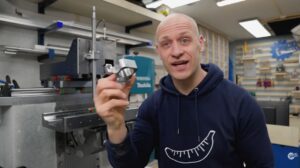
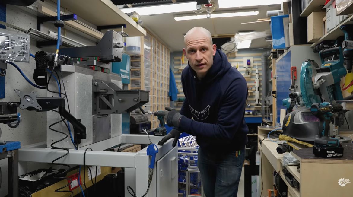
I’m Emiel, The Practical Engineer. If you’ve been following my 5-axis CNC build, you’ll know the project recently hit a significant milestone: a 400 kg, high-rigidity frame built from steel and concrete. With that cured and solid, I moved on to the Z-axis assembly — only to run into a physical bottleneck that threatened to stall the entire build.
A Design That Almost Worked
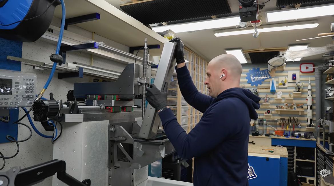
I already knew the space around the Z-axis would be tight. In Fusion 360, the design looked like it should clear. But once I started physically assembling the parts, it became obvious that something was wrong: the spindle nut mount collided with the linear rail carriages.
Not by much, but enough that the entire assembly simply could not move.
Frustrating, of course. But I’ve been engineering long enough to know this is part of the process. Especially on personal projects like the ones I build for The Practical Engineer, often in the evening hours, small things sometimes slip through. The real engineering starts after that moment. How do you solve the problem without redesigning half the machine?
Why I Only Wanted to Redesign One Part
At that point, I had two options. I could redesign the larger structural parts and move the linear rails further apart, or I could try to solve the issue by redesigning only the spindle nut mount.
The rest of the machine was already correct, rigid, and expensive to remake. Redesigning everything would have cost a massive amount of time and money.
The challenge became simple: could I redesign this single part so it would fit in an extremely tight space, while still keeping it strong and rigid enough? That turned into a genuinely interesting engineering puzzle.
Back to CAD: Optimising the Geometry in Fusion 360
I went back into Autodesk Fusion and started optimising every millimetre of available space.
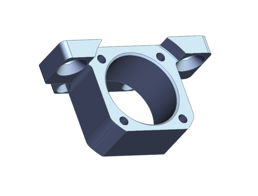
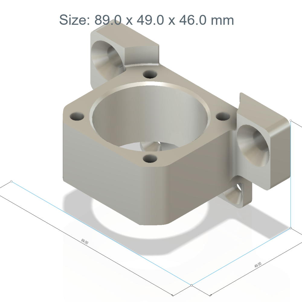
The first version of the mount already had clearance cutouts, but I had missed something important: the spindle nut, the mounting bolts, and the rail carriages all needed space in the same very small area. Once I sectioned the model in CAD, the issue became obvious.
The redesigned version became much flatter and more compact. I lowered the spindle nut position, optimised the shape around the rail blocks, and removed every bit of unnecessary material I could. In some places, the final clearance was only about 1 mm.
Tight, but enough.
Why This Part Needed to Be CNC Machined
For the new version, I chose steel and had the part CNC machined. 3D printing was not the right option here. This mount is part of the Z-axis drive system and needs to stay rigid under load. Any flex in this component would directly affect the stiffness and accuracy of the machine.
The difficult part was finding the balance between two things: keeping the part compact enough to fit, and keeping it strong enough to do its job. That balance is exactly what made this part interesting.
Having the Part Manufactured by Xometry
Once the redesign was finished, I uploaded the CAD file to Xometry.
For a project like this, that kind of service is extremely useful. Some parts are either too precise, too time-consuming, or simply not realistic to make in the workshop. This spindle nut mount was one of them.
The process was straightforward. I uploaded the model, selected the material and manufacturing method, checked the price, and ordered. The part arrived in roughly six working days, which was surprisingly fast — and in this case, it really helped keep the project moving.

The Moment of Truth
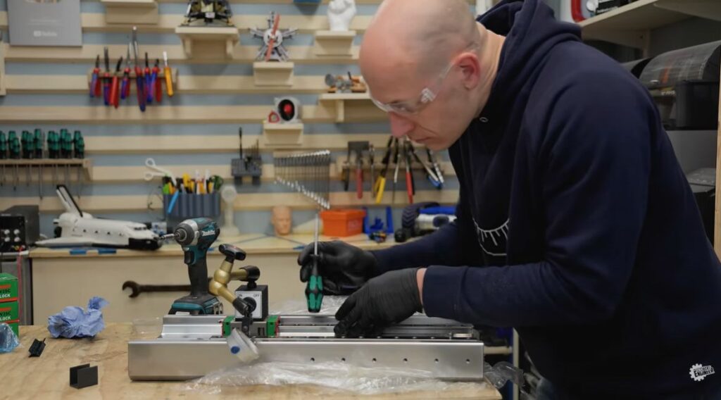
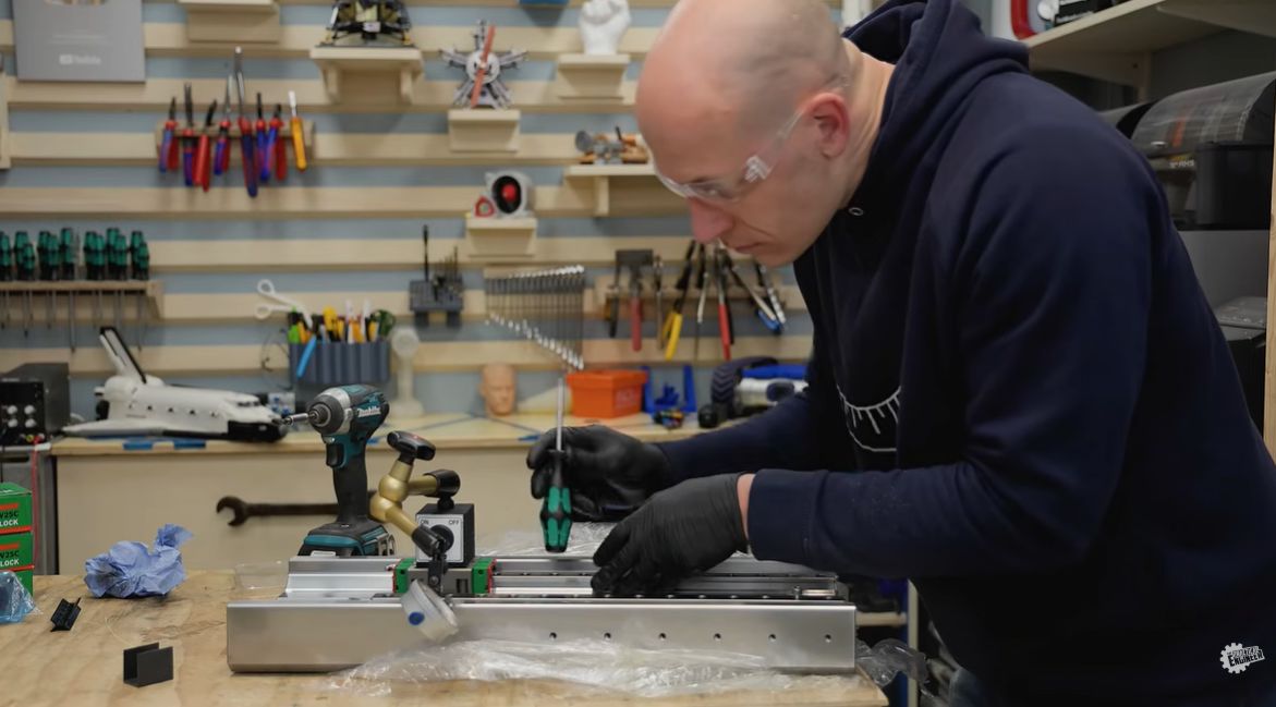
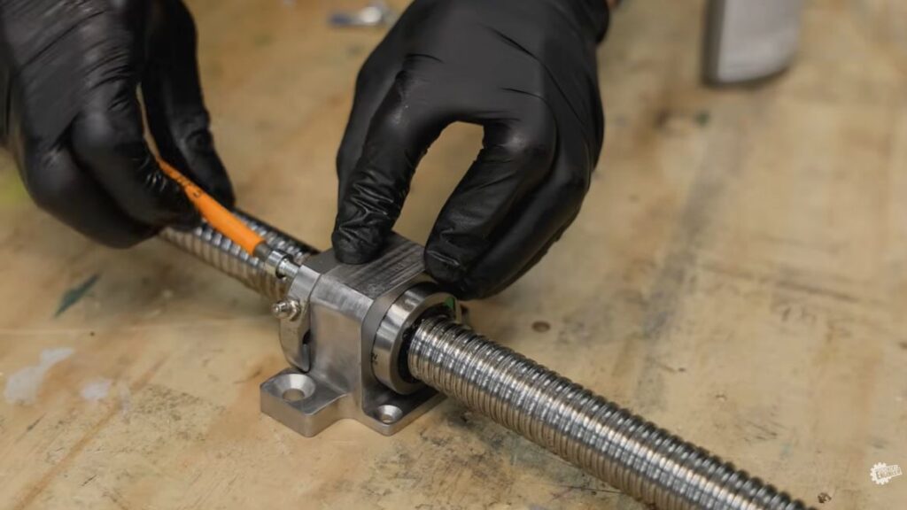
I ordered the part from Xometry and, when it arrived roughly six working days later, I installed it into the Z-axis assembly straight away.
This time, it fit.
The rail carriages cleared the mount, the spindle nut aligned correctly, and the Z-axis could finally move freely. Considering how heavy the whole assembly had become, seeing it mounted and working felt extremely satisfying. It wasn’t just that the part fitted. It meant I could finally continue with the machine.
Why These Problems Are Actually Fun
As frustrating as these moments can be, this is also one of the things I enjoy most about engineering projects.
You run into a constraint. You rethink the design. You optimise the geometry. You puzzle your way through the problem until you find a solution that works. Often, the final solution is better than the original idea.
That is also why I like sharing these projects on The Practical Engineer — not only the finished machine, but also the mistakes, redesigns, and practical problem-solving that happen along the way. That is where the real engineering is. You can follow the full journey, from the booster backpack to the magnetic couplings experiment and the 5-axis CNC build, right here on Xometry Pro.
What Comes Next
Now that the Z-axis assembly is working, I can continue toward the next big milestone: getting the machine running as a functional 3-axis CNC.
After that, the plan is to use the machine to make parts for the 4th and 5th axes. Once the machine can start making parts for itself, the project enters a completely new phase — and that is the part I am really looking forward to.
Watch the full Z-axis build and the 1 mm fix in action on The Practical Engineer’s YouTube channel:

Manufacturing stories & cases

Share your engineering or manufacturing story
If you want to share your story with others on xometry.pro, just fill out a short form
Share Your Engineering or Product Design Story
- We’re looking for stories about innovative mechanical engineering solutions, the design and development of mechanical components, or the creation of cutting-edge hardware products.
- Our team will assist you in preparing your story and translating it into several languages.
- Plus, you’ll receive a reward of 300 EUR to be redeemed with Xometry after your story is published*.


Comment(0)