Inserts enhance the strength and durability of plastic parts by providing reinforcement, secure attachment points, wear resistance, versatility, consistency, and cost-effectiveness. By incorporating inserts into a design, manufacturers can produce high-quality plastic components that meet performance requirements and withstand real-world applications.
Types of Inserts for Plastic Parts
Standard inserts typically refer to commonly used or readily available inserts that conform to industry standards in terms of dimensions, materials, and design. Threaded inserts for 3D printed parts, injection molding, and CNC machined plastics are widely used across various manufacturing sectors and are often easily accessible from suppliers and distributors.
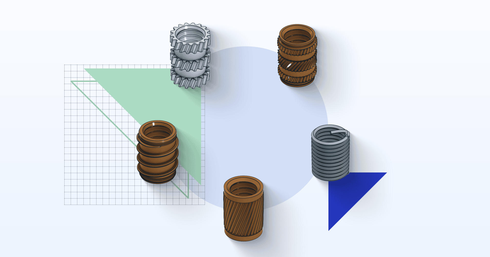
There are different types of standard inserts available in the market. The most commonly used types are press-fit inserts, tapping inserts, heat-set inserts, helical inserts, mold-in inserts, and dowel pin inserts.
When selecting plastic options for inserts, thermoplastics and thermosets offer different advantages. Thermoplastics (e.g. PMMA / Acrylic, PC, ABS, PP, PEEK), which can be reshaped multiple times, work well with heat and ultrasonic inserts. In contrast, thermosets (e.g. epoxy, vulcanised rubber), which are permanently rigid after molding, require specialized inserts like molded-in, press-in, or self-tapping inserts.
This article aims to provide comprehensive information on these inserts, the best plastics for each insert type, insert testing, and picking the right insert to add threads to your plastic parts.
Press-Fit Inserts
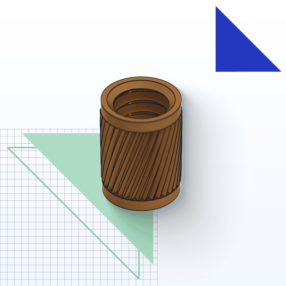
Press-in inserts are designed to be pressed into a straight post-mold hole without additional heat, making them ideal for softer plastics. They feature knurls to provide torque and pull-out resistance while ensuring good plastic flow during insertion. Depending on the insert type, knurls can be helical or diamond-shaped.
Standard press-fit inserts typically have helical knurls that bite into the plastic as they are pushed in, guiding the insert into the hole during tightening. This design ensures adequate installation torque to maintain the necessary tension between the threads.
In addition to standard press-fit inserts, screw-to-expand varieties have diamond knurls. These inserts are pushed into a hole, and then a screw is installed to expand the insert, driving the knurls into the surrounding plastic for a secure fit.
These designs allow for rapid installation without specialised tools, providing reliable joint performance.
- • Electronic Enclosures: Press-fit inserts are widely used in the manufacturing of electronic enclosures, chassis, and housing components. They provide secure attachment points for screws, standoffs, or other fasteners, ensuring the integrity and durability of electronic devices and equipment.
- • Automotive Components: Press-fit inserts are used in the automotive industry to secure plastic panels, trim pieces, interior components, and dashboard assemblies. They reinforce threaded connections in plastic parts and withstand vibrations, impacts, and temperature variations in automotive environments.
- • Industrial Equipment: Press-fit inserts are integrated into plastic components used in industrial machinery, equipment, and tools to provide secure mounting points for accessories and ensure the stability, durability, and functionality of industrial equipment in demanding manufacturing environments.
Standard Sizes of Press-Fit Inserts
Below is a data table from Spirol highlighting different sizes for their Series 50 press-fit insert. For accurate insert sizing, reference your preferred manufacturer’s specification sheets and use the table below as an example of the provided parameters. Moreover, the image below indicates what the measurements refer to in the table.

| Thread Size (UNC/UNF) | A
Overknurl Diameter (in) |
P
Pilot Diameter (in) |
L
Length (in) |
Recommended Hole Diameter (in) |
| Tolerance > | Ref. | +-0.003 | +-0.005 | +0.003 |
| 2-56 UNC | 0.134 | 0.121 | 0.125 | 0.124 |
| 4-40 UNC | 0.165 | 0.152 | 0.140 | 0.155 |
| 6-32 UNC | 0.196 | 0.183 | 0.150 | 0.186 |
| 8-32 UNC | 0.227 | 0.214 | 0.185 | 0.217 |
| 10-24 UNC | 0.259 | 0.246 | 0.250 | 0.249 |
| 10-32 UNF | 0.259 | 0.246 | 0.250 | 0.249 |
| 1/4-20 UNC | 0.321 | 0.308 | 0.312 | 0.311 |
| 5/16-18 UNC | 0.384 | 0.371 | 0.375 | 0.374 |
Tapped Inserts

Self-tapping inserts are designed for post-mold installation and provide the best pull-out resistance. The external threads are thin-profiled to minimise stress on the plastic, paired with a relatively coarse pitch to maximize the plastic shear surface and prevent pull-out. These inserts are generally recommended for softer thermoplastics or thermosets to avoid cracking.
The issue of installation torque is not a concern because tightening the connection increases the friction between the plastic and threads. Additionally, the larger diameter of the external insert thread increases the frictional surface. Furthermore, the back-out torque performance depends on the greater surface area of the external insert thread and the tension between the threads and plastic.
- • Lighting Fixtures and Displays: Tapping inserts are used to manufacture lighting fixtures, displays, and signage to create threaded connections in plastic housings, mounting brackets, and structural components. They provide secure attachment points for electrical components, LEDs, and signage elements, ensuring structural integrity and safety.
- • Furniture and Fixtures: Tapping inserts are commonly used in the furniture and fixtures industry to assemble plastic parts, such as chair components, drawer slides, and modular furniture systems. They facilitate easy assembly and disassembly while providing strong and durable threaded connections.
- • Consumer Products: Tapping inserts find applications in various consumer products, including appliances, toys, household items, and recreational equipment. They provide reliable fastening solutions for assembling plastic components, such as handles, knobs, hinges, and mounting brackets, ensuring product durability and performance.
- • Automotive and Aerospace: They are also used in the automotive and aerospace industries to join trims and plastic components.
Standard Sizes of Tapping Inserts
Below is a reference data table from McMaster highlighting different sizes for their plastic tapping inserts. For accurate insert sizing, reference your preferred manufacturer’s specification sheets and use the table below as an example of the provided parameters.
| Thread Size (UNC) | Installed Length (in) | Insert Diameter (in) | Recommended Hole Size (in): -0.000+0.004 |
| 2-56 | 0.236 | 0.177 | 0.157 |
| 4-40 | 0.236 | 0.177 | 0.157 |
| 6-32 | 0.315 | 0.236 | 0.209 |
| 8-32 | 0.315 | 0.256 | 0.228 |
| 10-24 | 0.394 | 0.315 | 0.283 |
| 1/4-20 | 0.551 | 0.394 | 0.339 |
| 5/16-18 | 0.591 | 0.472 | 0.417 |
| 3/8-16 | 0.709 | 0.551 | 0.496 |
| 1/2 | 0.866 | 0.630 | 0.575 |
Heat-Set Inserts
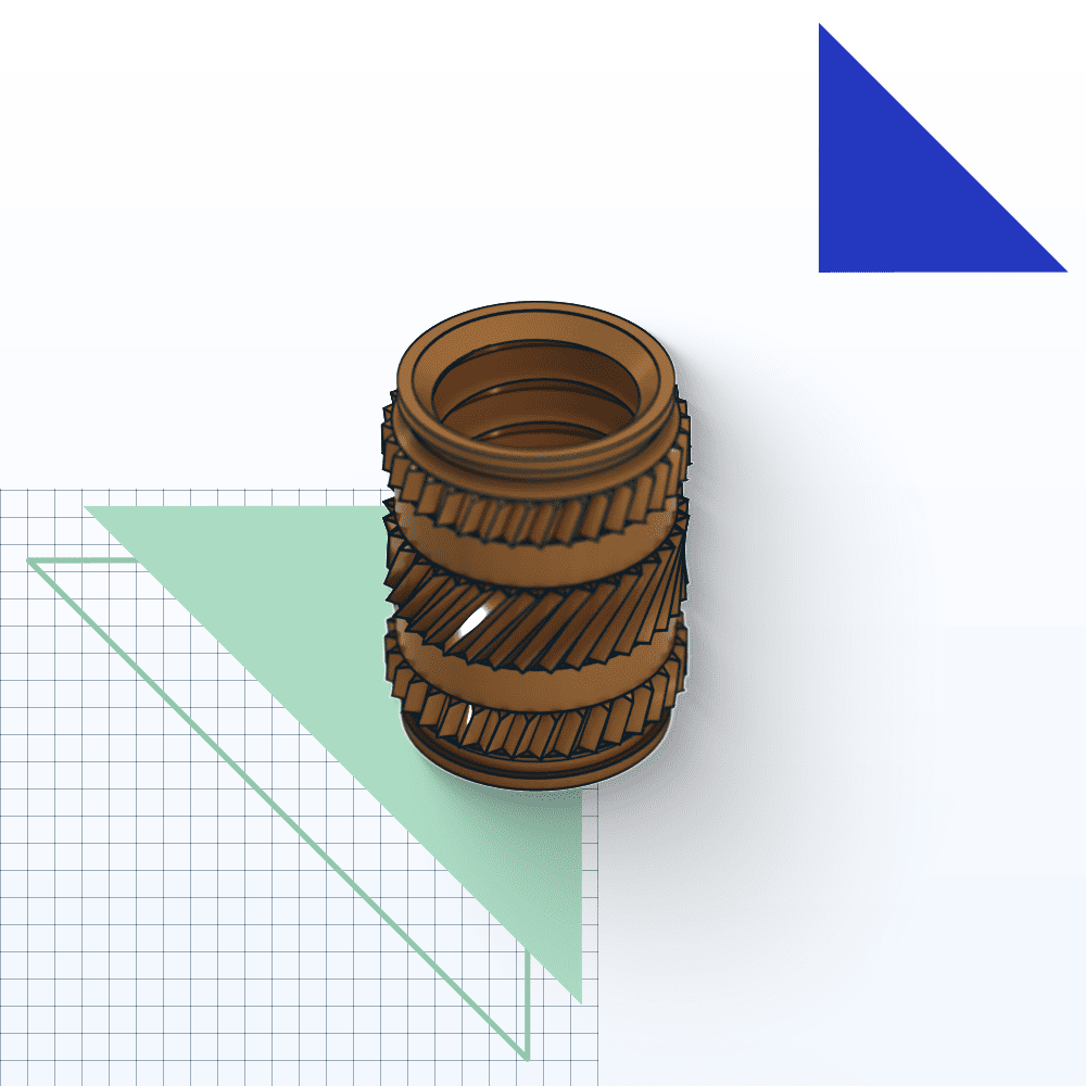
Heat-set inserts, also referred to as heat-staking inserts, are heated and pressed into pre-molded holes in plastic parts. As the insert cools, it forms a strong bond with the surrounding plastic, creating a secure attachment point for fasteners.
Heat-set inserts are well-suited for thermoplastics in 3D printing since, upon installation, the thermoplastic undergoes melting and reflow around the insert. This process makes the plastic surrounding the insert stronger in that area, ensuring a firm connection between the metal insert and the thermoplastic material.
Two primary methods for installing these inserts are heat-staking and ultrasonic insertion:
- Heat-Staking: This process involves heating the insert with a thermal press. As the insert is pressed into the plastic part, it melts a small portion of the surrounding plastic. This softened resin flows into the knurl pattern on the insert and hardens once the thermal press is removed, forming a strong bond.
- Ultrasonic Insertion: This method uses high-frequency vibrations to generate heat and melt the plastic around the hole. However, it is less commonly used because it requires precise control and is more challenging to automate than heat-staking.
The two main types of knurl inserts for heat-staking/ultrasonic installation, straight and tapered, offer flexibility depending on the application. Tapered inserts are particularly advantageous as they are self-aligning, making installation easier and faster.
- • Appliances: Heat-set plastic inserts are used to manufacture household appliances such as refrigerators, washing machines, and dishwashers. They provide secure mounting points for various components, including handles, hinges, and control panels, ensuring their functionality and longevity.
- • Automotive and Aerospace: They are also used in the automotive and aerospace industries to join trims and plastic components.
- • Medical Devices: Heat-set inserts are used to manufacture medical devices and equipment, creating sterile and hygienic attachment points in plastic housings, instrument panels, and enclosures. They meet strict regulatory requirements for medical device assembly and sterilization processes, ensuring product safety and reliability.
Standard Sizes of Heat-Set Inserts
Below is a reference data table from Spirol highlighting different sizes for their tapered hole (Series 19 short) heat/ultrasonic insert. For accurate insert sizing, reference your preferred manufacturer’s specification sheets and use the table below as an example of the provided parameters.
| Thread Size (UNC/UNF) | A
Overknurl Diameter (in) |
P
Pilot Diameter (in) |
L
Length (in) |
Recommended Hole Diameter (in) |
| Tolerance > | Ref. | +-0.003 | +-0.005 | +0.003 |
| 2-56 UNC | 0.141 | 0.123 | 0.125 | 0.126 |
| 4-40 UNC | 0.182 | 0.154 | 0.140 | 0.157 |
| 6-32 UNC | 0.213 | 0.185 | 0.150 | 0.188 |
| 8-32 UNC | 0.246 | 0.218 | 0.185 | 0.221 |
| 10-24 UNC | 0.277 | 0.249 | 0.250 | 0.252 |
| 10-32 UNF | 0.277 | 0.249 | 0.250 | 0.252 |
| 1/4-20 UNC | 0.340 | 0.312 | 0.312 | 0.315 |
| 5/16-18 UNC | – | 0.374 | – | 0.377 |
Helical / Helicoil® Inserts
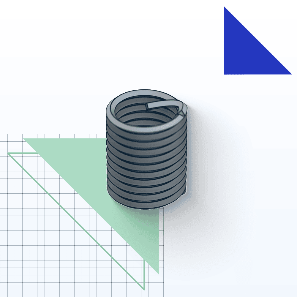
Helical inserts, often called coil inserts or thread inserts, are coil-shaped inserts made from materials like stainless steel or brass. They are used to reinforce or repair threaded holes in plastic components that have become stripped or damaged. Helical inserts provide a durable and long-lasting solution for restoring the integrity of threaded connections in various applications.
How to Install a Helical Insert
Installing a helical insert requires some additional work compared to other inserts, as you need to add a thread to your assembly to be able to screw in a helical insert.
Here are the basic steps:
- Drill a hole in the plastic component. Ensure the hole size matches the manufacturer’s specification sheet.
- Tap the hole using a tapping tool (sold at most insert manufacturers or hardware stores).
- Screw the insert into the hole using an installation tool (also sold at most insert manufacturers).
- Break off the insert prong using a punch or pushing a screwdriver through the insert.
- • Repairing Stripped Threads: One of the primary applications of helical inserts is to repair stripped or damaged threads in metal or plastic components. By inserting a helical coil into the damaged hole, the original thread profile is restored, allowing for a secure and reliable connection with screws or bolts.
- • Preventing Thread Wear: In applications where components are frequently assembled and disassembled, such as in machinery or equipment maintenance, helical inserts can help prevent wear and damage to threaded holes. By providing a more durable thread surface, helical inserts prolong the lifespan of components and reduce the need for costly repairs or replacements.
- • Enhancing Load-Bearing Capacity: Helical inserts can increase the load-bearing capacity of threaded connections by distributing stress more evenly across the fastener and surrounding material. This is particularly useful in applications where components are subjected to high loads or vibrations, such as in aerospace, automotive, or industrial machinery.
Standard Sizes of Helical Inserts
Below is a reference data table from McMaster highlighting different sizes for their stainless steel helical insert. For accurate insert sizing, reference your preferred manufacturer’s specification sheets and use the table below as an example of the provided parameters.
| Thread Size (UNC/UNF) | Installed Length (in) | Drill Bit Size | For Max Hole Diam. (in) |
| 4-40 UNC | 0.112 | No. 31 | 0.12 |
| 6-32 UNC | 0.138 | No. 25 | 0.1495 |
| 8-32 UNC | 0.164 | No. 16 | 0.177 |
| 10-24 UNC | 0.19 | No. 5 | 0.2055 |
| 10-32 UNF | 0.19 | 13/64” | 13/64” |
| 1/4-20 UNC | 1/4 | H | 0.266 |
Molded-In Inserts
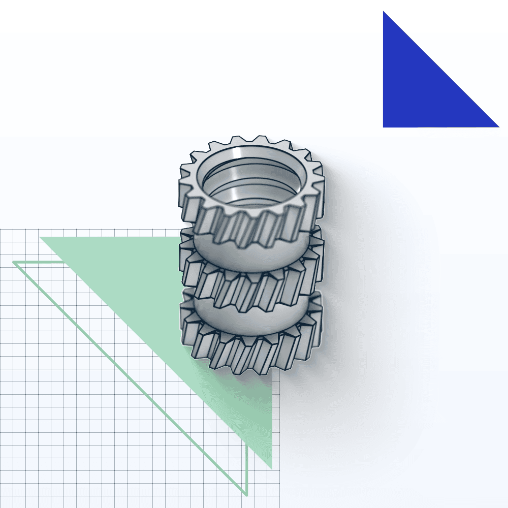
Molded-in threaded inserts are used in the injection molding process, where pins are machined or inserted into the mold core. During the molding process, the inserts are completely encapsulated with the resin, resulting in a high bond quality and eliminating the need for additional insertion steps post-molding.
However, the process demands a more complex core design with precise tolerances between the pins and inserts. Additionally, placing the inserts for each cycle can be time-consuming.
Despite the higher initial costs compared to post-mold installation processes, molded inserts offer superior performance. Their design significantly impacts pull-out resistance and torque, particularly the length and diameter. Helical knurls are often preferred to maximise torque resistance for a given diameter. Proper plastic encapsulation in the insert’s undercuts is essential for achieving the necessary pull-out resistance during service.
- • Securing Components in Plastic Assemblies: One of the primary applications of molded-in inserts is to provide strong and durable threaded connections in plastic assemblies. By embedding the insert during the molding process, the plastic component can securely hold screws or bolts, preventing thread stripping and loosening. This application is crucial in consumer electronics, automotive interiors, and household appliances where reliable fastenings are essential.
- • Improving Mechanical Strength and Durability: Molded-in inserts enhance the mechanical strength and durability of plastic parts by providing metal-to-metal connections. This is especially important in applications requiring frequent assembly and disassembly or where the parts are subjected to high stress and loads. Industries such as aerospace, automotive, and medical devices utilize molded-in inserts to ensure components can withstand rigorous use without degrading the plastic material.
- • Providing Electrical and Thermal Conductivity: Molded-in inserts can also provide electrical and thermal conductivity in plastic components. By integrating conductive inserts, plastic parts can be designed to facilitate grounding, shielding, or heat dissipation. This application is particularly useful in the electronics and telecommunications industries, where maintaining electrical performance and managing heat is critical for the functionality and longevity of devices.
Standard Sizes of Molded-In Inserts
Below is a reference data table from Spirol highlighting different sizes for their aluminium through-hole molded-in inserts (Series 63). For accurate insert sizing, reference your preferred manufacturer’s specification sheets and use the table below as an example of the provided parameters.
| Thread Size (UNC/UNF) | A
Outer Diameter (in) |
L
Length (in) |
L
Min. Minor Diameter (in) |
| Tolerance > | Ref. | +-0.005 | +-0.005 |
| 8-32 UNC | 0.272 | 0.256 | 0.380 |
| 10-24 UNC | 0.309 | 0.325 | 0.459 |
| 1/4-20 UNC | 0.367 | 0.394 | 0.610 |
| 5/16-18 UNC | 0.463 | 0.463 | 0.697 |
How to Choose the Right Insert
Here are a few key considerations to keep in mind when selecting an insert type for your parts:
Strength Requirements (Pull-Out and Torque)
The key strength factors for inserts are their resistance to being pulled out of the part (pull-out force) and twisting within the part when the mating fastener is torqued (torque-out force). A longer insert increases pull-out resistance, while a larger diameter insert enhances torque capacity.

Due to the complexity of component design and the wide variety of options, it can be difficult to calculate the exact pull-out and torque forces for a specific application. This would require physical testing. However, a close approximation can be calculated using the von Mises yield criterion.
Materials
Both the plastic material and the insert material matter, depending on the application. Heat-staking and ultrasonic inserts only work with thermoplastics. For thermosets, the options are molding in the insert, or cold pressing the insert in later, where the elasticity of the resin material will become critical.
The most common material for threaded inserts is brass. However, lead-free alternatives such as stainless steel or aluminium are becoming more popular due to increasing sustainability requirements. Stainless steel offers better strength and corrosion resistance, and aluminium inserts are about 70% lighter than brass.
Use the below table as a reference, but ensure you check with your preferred manufacturer on the best plastic to use for a specific insert series. Also, it is advised to determine the shear strength of your material to know whether it can handle the torque or pull-out resistance of your application.

Cost
Because threaded inserts can be molded into the part at the outset, or pressed into the part later, consider the total cost of the operation. That includes molding time and cost, component handling, and assembly. For example, opting for molded-in inserts may not be the most cost-effective option if you are only creating prototypes to test basic functionality.
Manufacturing Technology
The manufacturing technology used to produce a plastic part should be considered when adding threaded inserts for a particular application.
| Technology | Insert Placement Methods | Special Considerations for Inserts |
| Injection Molding | Molded-in inserts placed before injection | Ensures strong bonds and precise placement |
| CNC Machining | Post-molding: press-fit, tapping, heat-set | Suitable for tight tolerances |
| 3D printing | During printing or post printing: heat-seat, press-fit | Requires higher infill around insert location for strength |
Threaded Inserts 3D Printing
| 3D Printing Technology | Insert Placement Methods | Special Considerations for Inserts |
| MJF | Post printing: heat-set, press-fit | Higher infill needed around inserts for strength |
| FDM | During or post-printing: heat-set, press-fit | Layer lines may affect precision, higher infill needed around inserts |
| SLS | Post-printing: heat-set, press-fit | Strong parts, higher infill needed around inserts |
| SLA | Post-printing: heat-set, press-fit | Smooth surface finish, higher infill needed around inserts |
| DMLS | Post-printing: heat-set, press-fit | Suitable for metal parts, higher infill needed around inserts |
| Carbon DLS | Post-printing: heat-set, press-fit | Fast production, strong parts, higher infill needed around inserts |
| Polyjet | Post-printing: heat-set, press-fit | High resolution, higher infill needed around inserts |
What to Pay Attention to When Reading Manufacturer’s Specification Charts
The standard sizes of inserts depend on the manufacturer and can vary significantly. Here are a few key pieces of data to look out for when reading a specification chart.
Material
Material options for inserts include brass inserts made with lead, brass alloy inserts, aluminium inserts, and 303 stainless steel inserts:
- Aluminium inserts are 70% lighter than their brass and stainless steel counterparts, offer good corrosion resistance and are lead-free. Their lead-free composition also allows for safe recycling.
- 303 stainless steel inserts are the strongest among brass and aluminium options. They have good corrosion resistance and are lead-free, making them safe for recycling.
- Brass inserts made with lead offer greater strength than aluminium and other brass alloys, though they are not as strong as 303 stainless steel inserts. They also provide good corrosion resistance.

Drill Bit and Hole Size
Insert specification charts will provide the correct drill size and maximum hole diameter recommended to avoid decreased performance. However, making the hole too small will induce undesired stresses and potential cracks in the plastic. Some manufacturers include a plus/minus tolerance to work within for optimal insert performance.
The diameter of the clearance hole in the mating component is also important. The insert, not the plastic, must carry the load. The hole in the mating component must be larger than the outside diameter of the assembly screw but smaller than the pilot or face diameter of the Insert. This prevents jack-out.

Tapered or Straight Hole
Straight inserts should be used in straight holes, and tapered inserts should be used in tapered holes. The manufacturer will state what degree of taper a hole should have for a specific insert. However, the standard recommendation is a taper of no more than 1 degree for straight holes and 8 degrees for tapered holes.
Hole Length
Holes should always be deeper than the length of the insert, and the assembly screw should never reach the bottom of a hole as jack-out would result (i.e., the insert will strip out the hole).
Manufacturers supply different-length inserts, so ensure you note the installed length. As a general rule of thumb, self-tapping inserts should be inserted into a hole with a minimum depth of 1.2 times the length of the insert. The minimum hole depth for other inserts should be the insert length plus 2 insert thread pitches.
Boss Diameter
The boss diameter (or wall thickness) refers to the raised section around the hole where the insert will be installed. This dimension is crucial to avoid bulging during installation. If a thicker wall around a hole cannot be achieved, adding ribs is an option to ensure optimal insert performance.
When viewing the manufacturer’s specification sheet, a recommended boss diameter is sometimes included. However, if not, design the boss diameter 2 to 3 times the insert diameter (sometimes called overknurl diameter).
Thread Size
Thread size refers to the inner thread of the insert, which determines what assembly screw will be used. Metric, UNC (Unified National Coarse), and UNF (Unified National Fine) thread sizes are available. UNC/UNF is primarily used in the United States.
Metric thread sizes are denoted by the letter “M” followed by the nominal diameter in millimetres. The pitch (distance between threads) can be specified but is sometimes omitted for coarse threads.
- M10 x 1.25 – nominal diameter of 10 mm with a pitch of 1.25 mm.
- M4 – nominal diameter of 4 mm with a standard pitch (0.7 mm if coarse).
Knurl Design
Knurls are essential for enhancing resistance to torque in various applications and are common on screw-to-expand, press-fit, and heat-set inserts. Straight knurls are generally preferred over diamond knurls due to their superior design. Coarser knurls, while increasing torque resistance, induce greater stress on plastic materials. Therefore, selecting the appropriate knurl coarseness is crucial to balance performance and material integrity.
The circumference of the insert is a key factor in determining the knurl pitch, which imposes practical limitations on the design of knurls. Helical knurls, in contrast to straight knurls, offer different benefits. While they lower torque resistance, they significantly increase axial pull-out resistance. Knurl angles between 30 and 45 degrees positively impact pull-out resistance with minimal torque loss.
In practice, several knurl bands with different helix angles can be combined on the same insert to achieve an optimal combination of torque and pull-out resistance. This multi-band approach allows for fine-tuning performance characteristics to meet specific application requirements.
How to Get Plastic Parts With Inserts Ordered at Xometry
On Xometry’s manufacturing sourcing platform, we have the capabilities to produce high-quality 3D prints in a variety of plastics, and pre-drill holes ready for any standard inserts. Need threaded inserts for plastics selected and added for you? We’ll do that too in order to meet your specific part strength requirements.
Whether you need components manufactured through CNC machining, 3D printing, or injection molding, our platform offers instant and manual quoting for a selection of thermoplastics and thermoset plastics.
Setting Threads and Inserts on Xometry’s Instant Quoting Engine
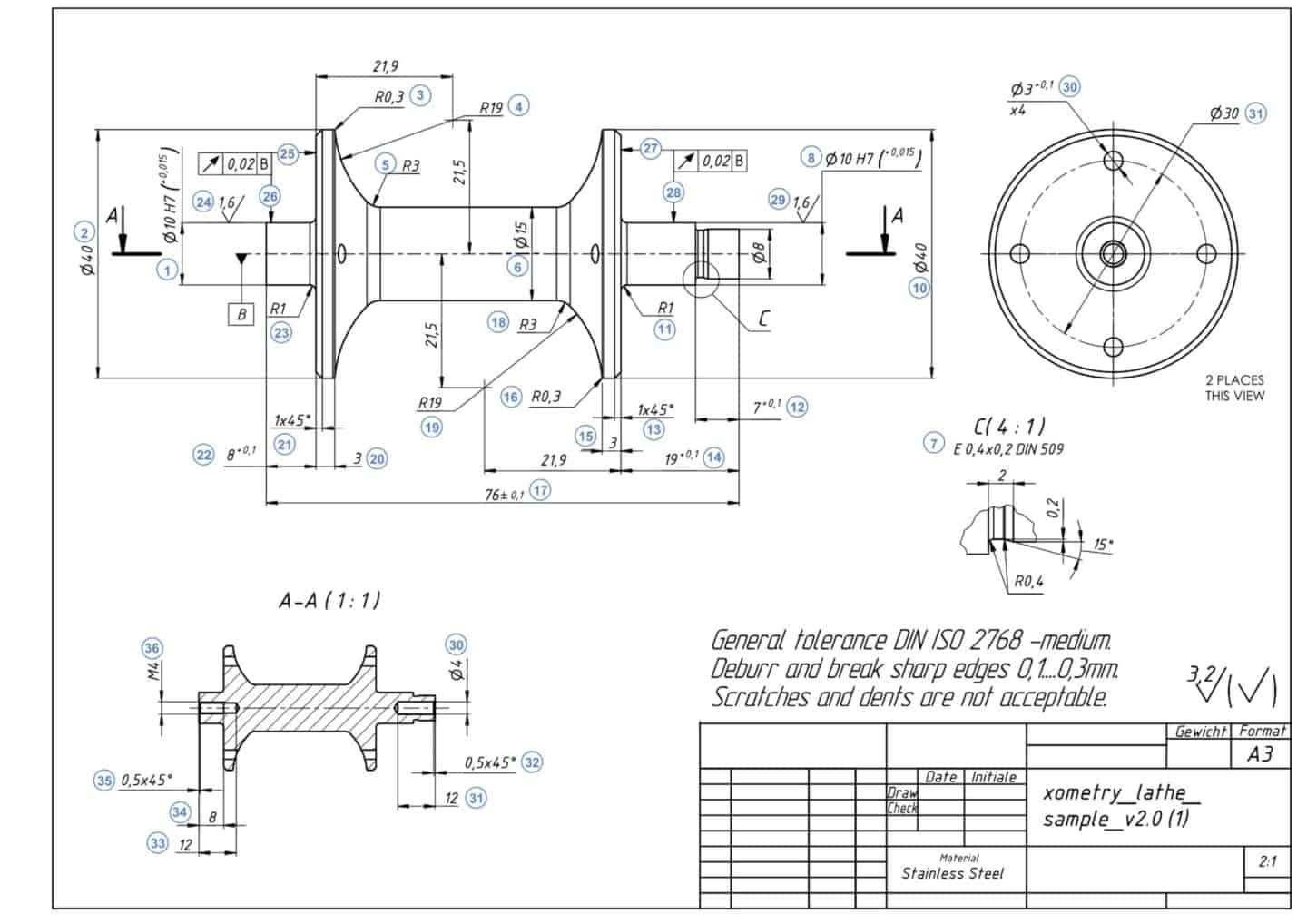
Note: If you skip the step of uploading a drawing and proceed with ordering your part, our sales engineers will contact you later to clarify the information about your inserts.
Do you doubt the process and material? Check out our materials library and our 3D printing materials decision tool. Then, simply upload your CAD file to our Instant Quoting Engine and receive a quote in a few clicks.
 Europe
  Türkiye
  United Kingdom
  Global

 Login with my Xometry account
  0
0





Comment(0)