

 Europe
  Türkiye
  United Kingdom
  Global








 Login with my Xometry account




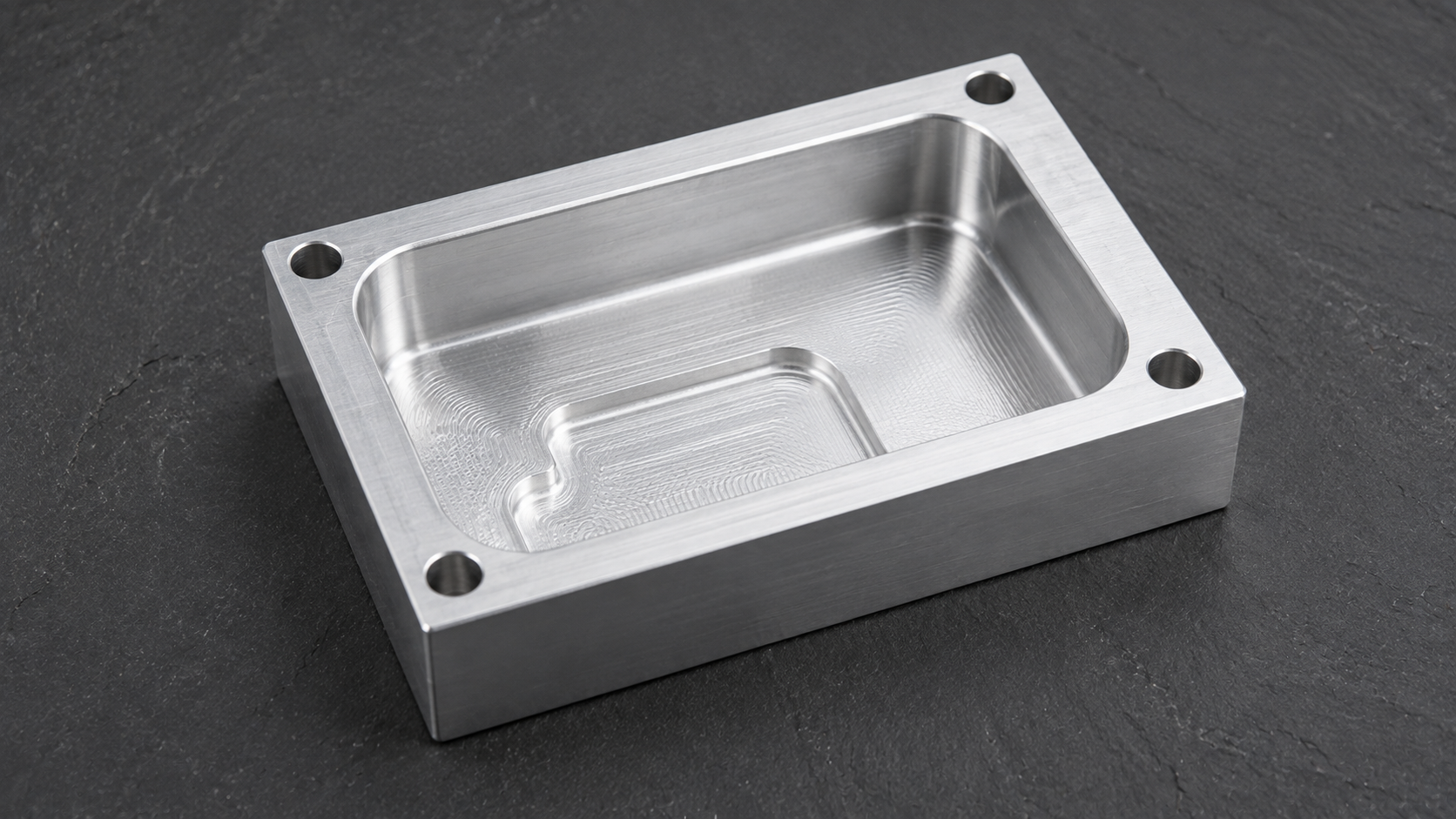
Pocket Milling Types
The shape of the pocket rarely drives difficulty. What matters is whether the boundary is open or closed, since that decides how the tool reaches depth and how chips clear the cut.
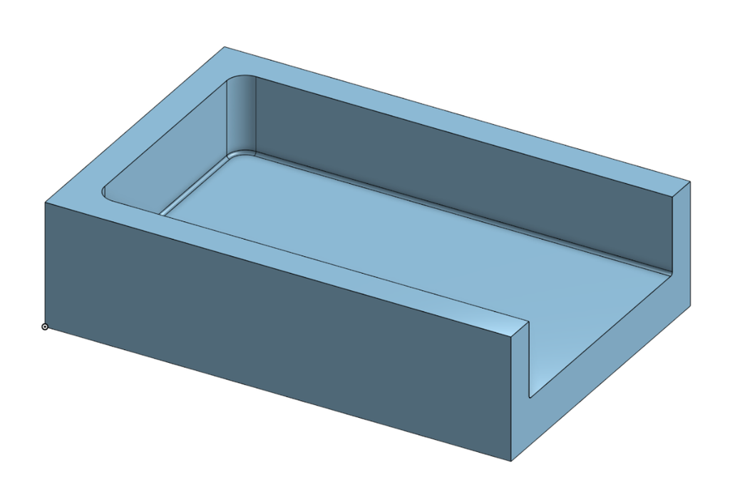
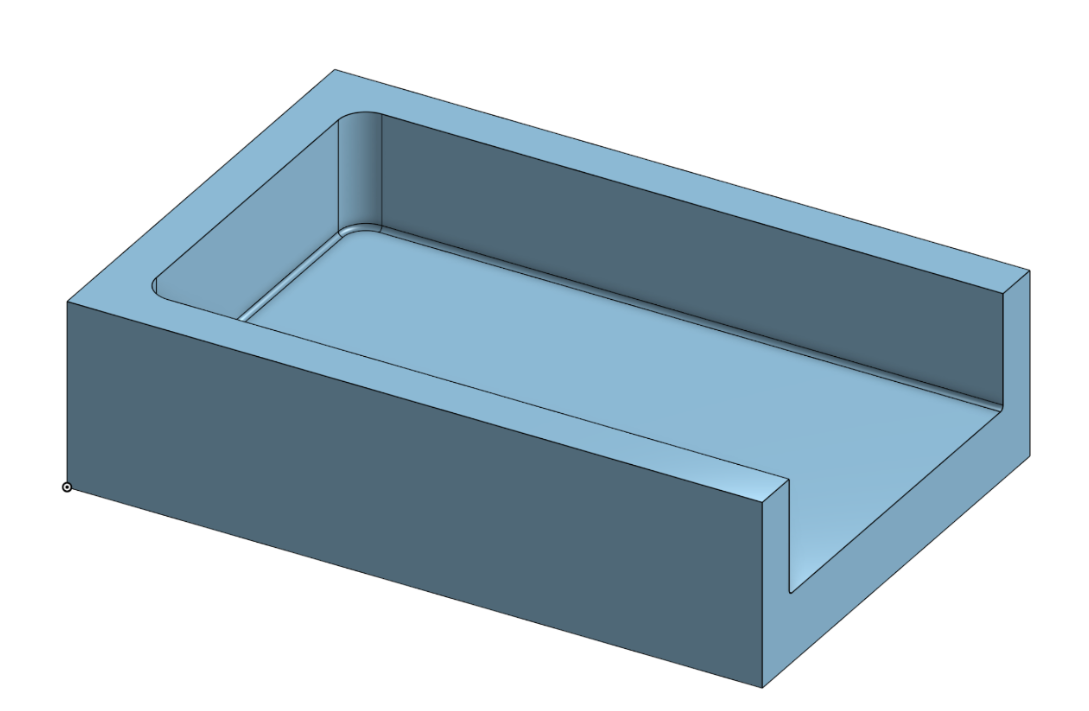
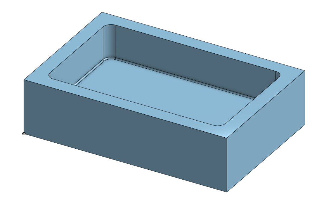
Open pockets
An open pocket breaks through at least one outer edge of the part. The tool can enter at final depth from the open side, chips fall clear without accumulating, fixturing stays simple, and a standard end mill handles the job without special entry planning.
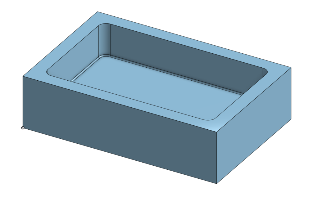
Closed pockets
A closed pocket is walled on all sides. The tool must reach depth before it can cut laterally, and chip evacuation becomes a separate problem the programmer has to solve.
Pockets with islands
A pocket with an island is an open or closed pocket with a raised feature left on the floor. It adds toolpath complexity but introduces no new physical requirement beyond what open or closed geometry already demands.
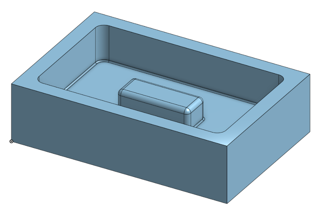
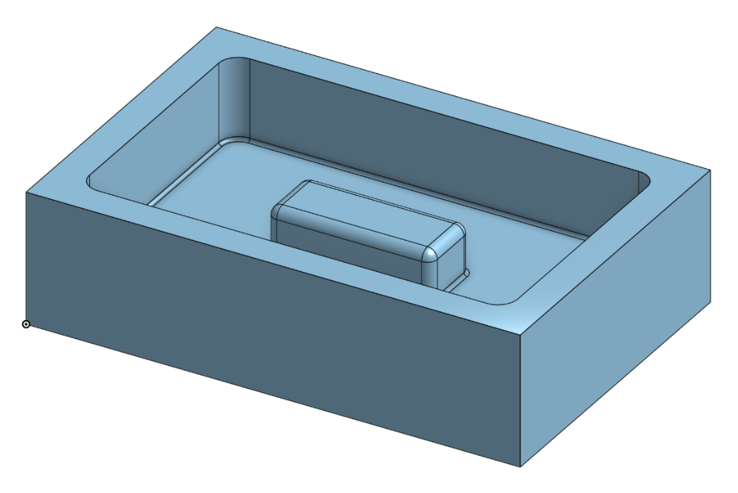
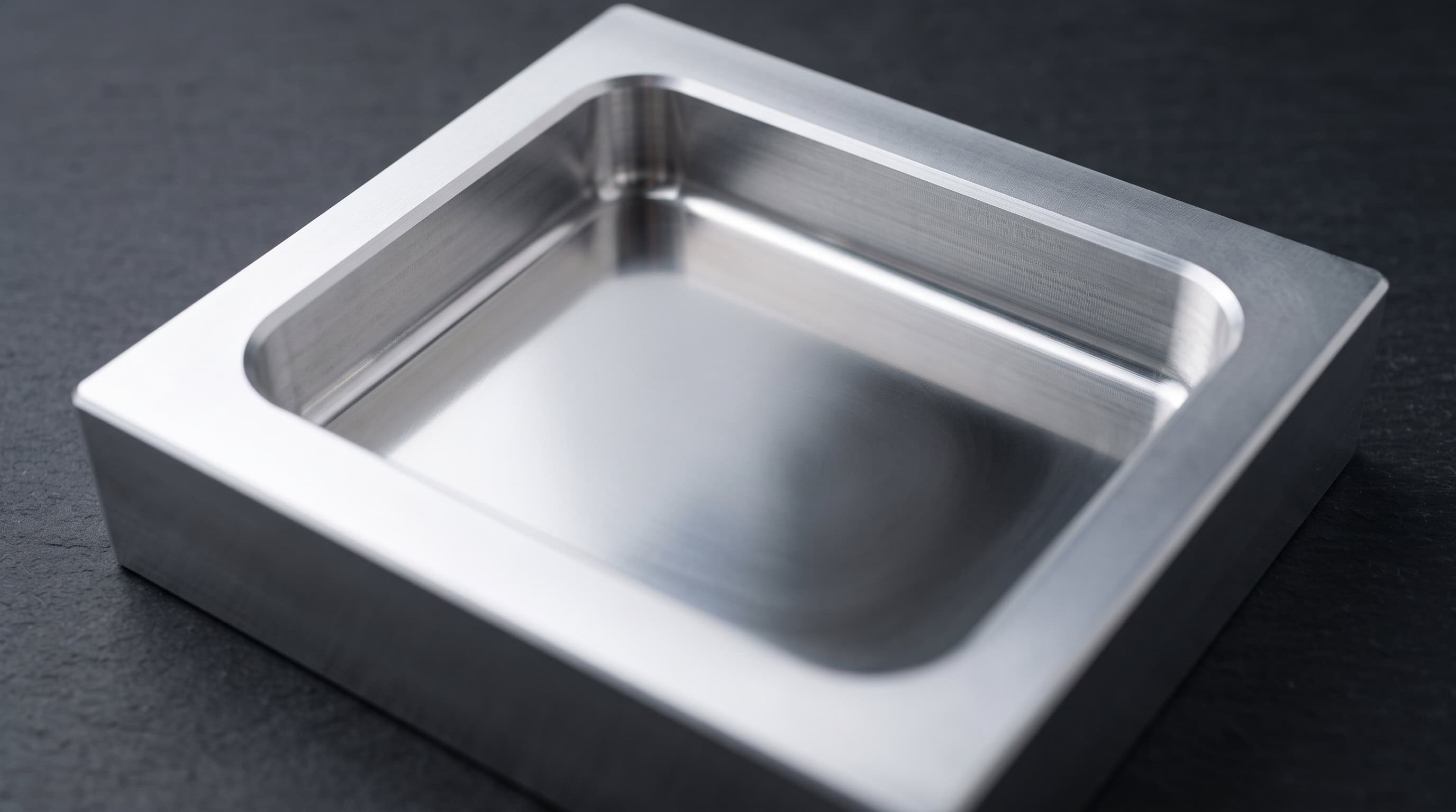
Open versus closed makes the largest difference in pocket milling difficulty, and therefore in cost. If one wall of a pocket can be opened without a loss of part function, open it. A large share of closed pockets are closed by default, not because the design genuinely requires it.
Milling Cutter Entry Methods
Pocket milling requires reaching depth before lateral cutting can begin, and not every end mill can plunge straight down along the spindle axis. A standard end milling cutter has a small non-cutting zone at the center, so a straight plunge rubs rather than cuts, builds heat, and often ends with a broken tool. Only a center-cutting end mill, sometimes called a slot drill, can plunge directly into solid material.
There are three in-spindle entry methods, plus one fallback.
Plunging
A center-cutting end mill drills straight down like a twist drill, then moves radially once it reaches depth. Plunging generates the highest cutting forces of the three methods, which accelerates tool wear.
Ramping
The cutter descends at an angle of roughly 2 to 5 degrees, reaching final depth over several passes rather than in one straight plunge.
Helical interpolation
The tool spirals downward, with the tool axis never leaving an area the size of its own diameter. This method puts the least stress on the tool and is the preferred default wherever geometry allows it.
Pocket Entry Method Comparison Table
| Entry Method | Tool Requirement | Radial Force | Best Use Case | Limitation |
| Plunging | Center-cutting end mill | High | Simple, shallow closed pockets | Fast tool wear |
| Ramping (2 to 5 degrees) | Standard end mill | Moderate | Medium-depth pockets | Needs entry ramp clearance |
| Helical interpolation | Standard end mill | Low | Preferred default | Bore must be at least 1.1x tool diameter |
| Pre-drilled entry | Any roughing tool | Low | Rescue option only | Extra tool change, added cycle time |
When none of the in-spindle methods fit, a shop can pre-drill a hole and drop a roughing tool into it. This is the least favored option because it adds tool changes, especially on parts with many entry points.
The initial roughing depth typically runs about 0.25 mm shallower than the drawing dimension, leaving material for a finishing pass to clean up the floor. On the design side, the only requirement is leaving enough clearance to allow ramping, or preferably helical interpolation, wherever the geometry permits it.
Toolpath Strategies
Two programs cutting the same pocket on the same machine can differ in cycle time by a factor of three depending on the toolpath. The strategy determines how steady the cutting force stays, and steady force is what protects the tool and the surface finish.
Roughing methods
Z-level, or contour, roughing clears the pocket layer by layer from the top down. It is simple and predictable, but material engagement spikes at corners as the tool wraps further into the stock.
Spiral and morphed-spiral paths move the tool in one continuous motion instead of stepping over in straight passes, which smooths cutting motion and often improves floor finish.
Trochoidal milling drives the cutter in small overlapping loops that keep radial engagement low and constant. This allows deep cuts in tough materials and clean cornering without chatter.
Adaptive clearing, also called dynamic milling, holds cutter engagement constant by flowing the tool along curved paths. The load never spikes, which allows deeper axial cuts at higher feed and extends tool life. Most pockets today combine adaptive roughing with a light contour pass to finish the walls.
Roughing Strategy Comparison Table
| Strategy | Radial Engagement | Corner Behavior | Typical Application |
| Z-level (contour) | Fixed, high at corners | Load spikes in corners | Simple pockets, soft materials |
| Spiral / morphed spiral | Moderate, continuous | Smooth | Better floor finish requirement |
| Trochoidal | Low, constant | Stable | Deep pockets, tough alloys |
| Adaptive / dynamic | Low, constant | Stable | Default modern strategy, longest tool life |
Roughing to finishing sequence
An accurate pocket is the result of three operations, not one. A back-and-forth roughing path leaves uneven ridges of leftover stock called scallops, and their size scales with stepover, typically 30 to 50 percent of the cutter diameter.


Feeding a finishing tool straight into that uneven material costs both tolerance and finish, since the tool faces a different depth of cut every few millimeters. The correct sequence is to rough out the bulk, run a semifinishing pass to bring the scallops to an even ground, then take a light finishing pass for the final result.
Design Rules for Cost Efficiency
CNC milling is a capable process, and cost control depends on a handful of DfM decisions made well before the part reaches the shop floor.
Respect the depth-to-diameter ratio
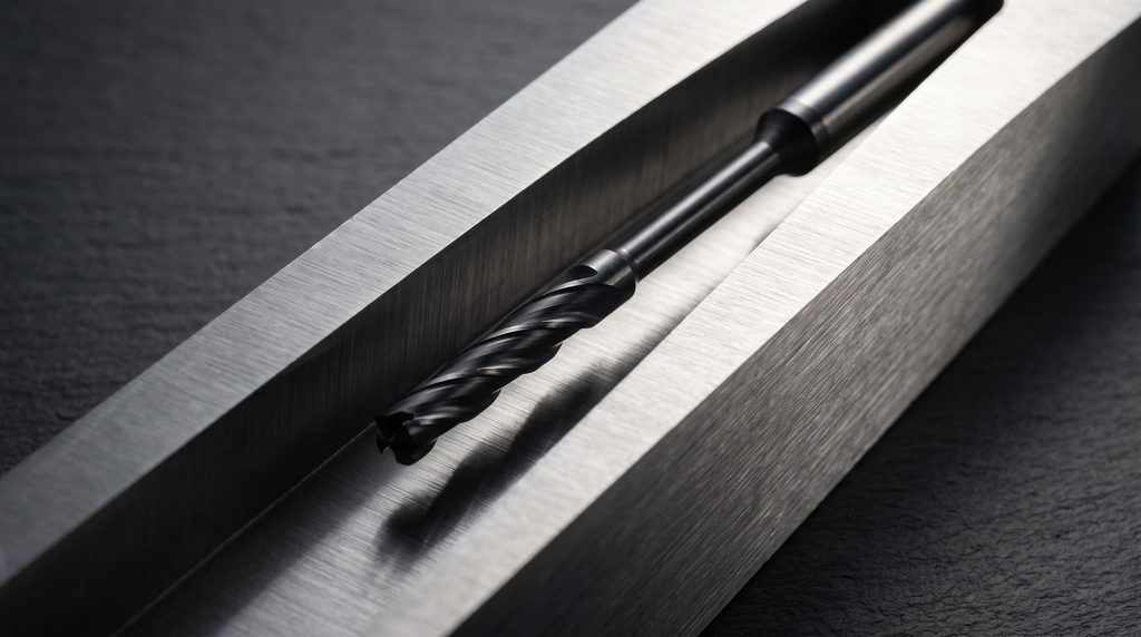
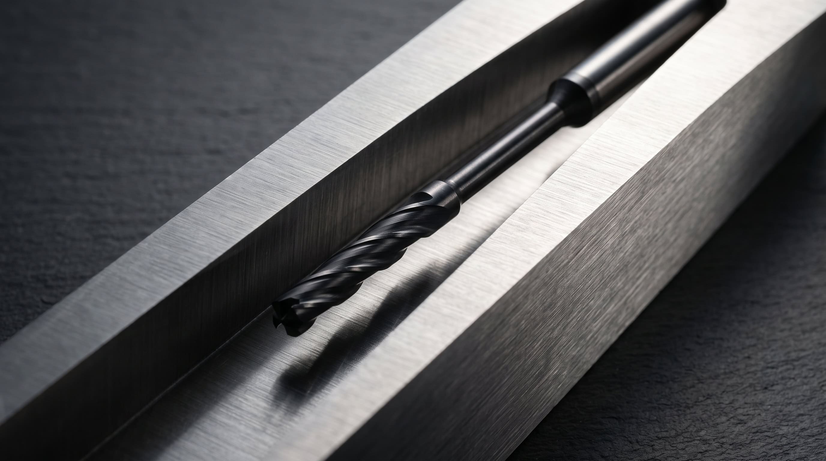
The single most consequential number in this guide is the depth-to-diameter ratio, comparing pocket depth to the diameter of the smallest tool that must reach the bottom.
Depth-to-Diameter Ratio Guidance
| Ratio (Depth: Tool Diameter) | Machining Condition | Practical Effect |
| Up to 3x | Stable | Standard end mills, high feed rates |
| 3x to 4x | Workable | Reduced speed, lighter cuts required |
| Above 4x | Deflection risk | Slower feeds, more passes |
| Above 5x to 6x | High risk | Vibration-damping toolholders, long cycle times required |
Three fixes address a ratio problem. First, make the pocket shallower to reduce depth. Second, make the pocket wider to fit a larger cutter. Third, take lighter passes, which does not change tool reach but lowers cutting force and deflection at each pass. The third option is not a substitute for the first two: a pocket at 6x depth-to-diameter can take four times as long to machine as the same pocket at 3x, since the long tool forces many shallow passes instead of a few aggressive ones.
Oversize internal corner radii
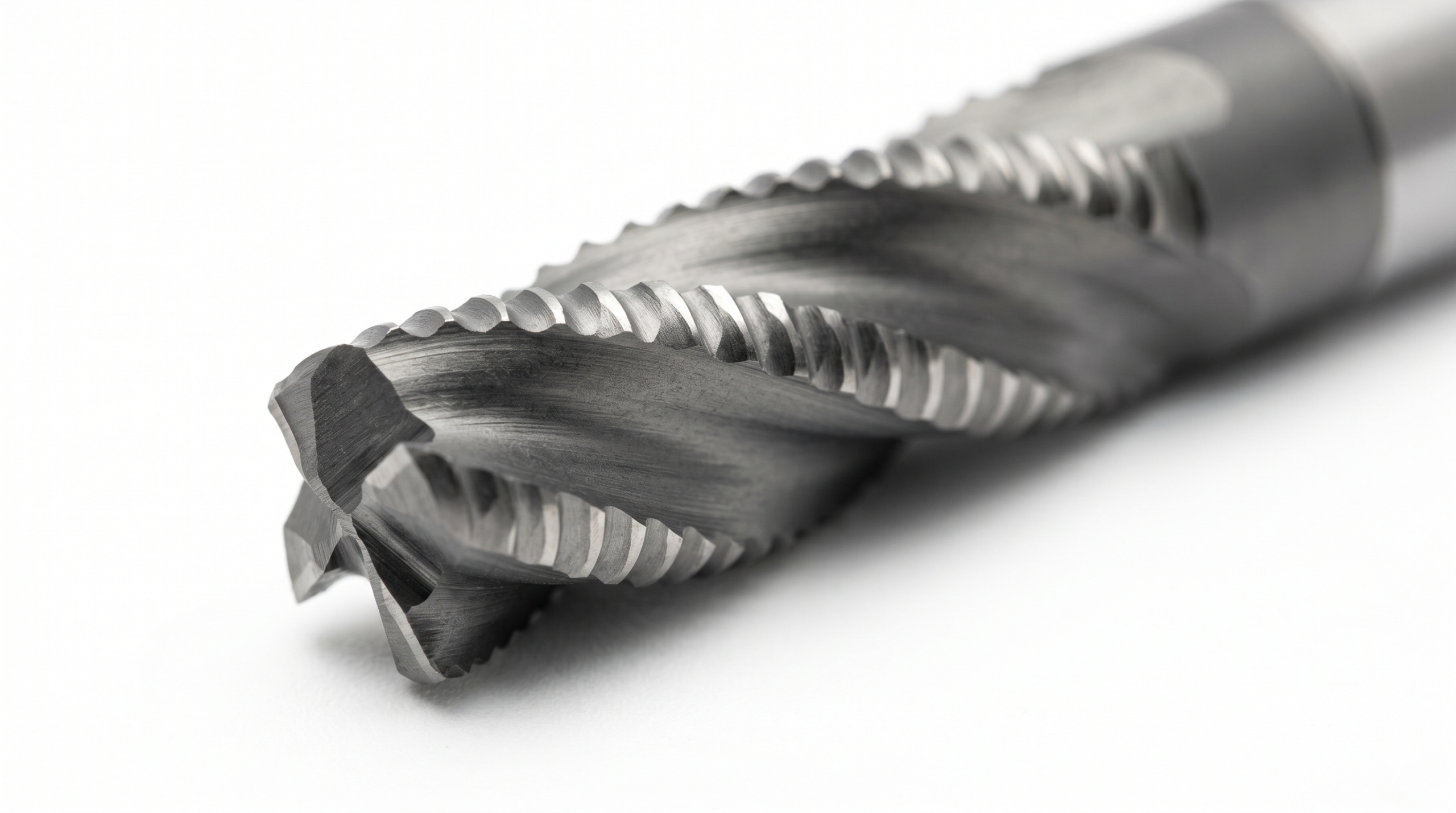
A round cutter produces a round corner. An internal corner radius can never come out smaller than the radius of the tool that cut it, so a sharp internal corner cannot be machined.
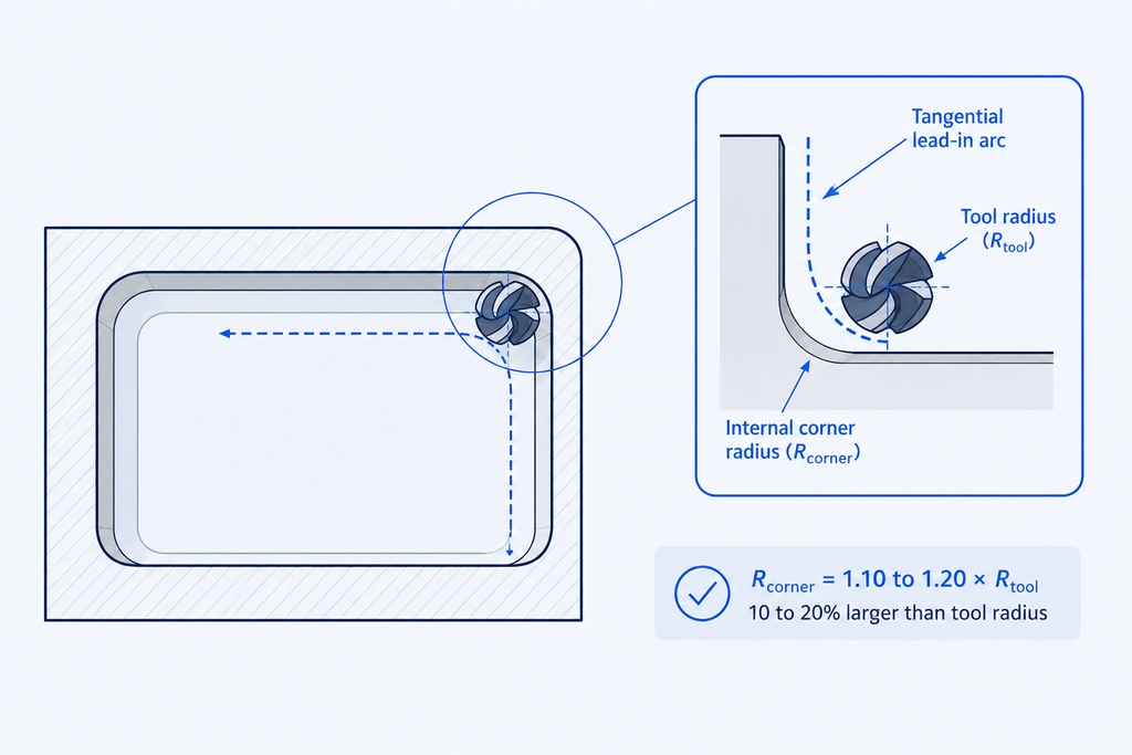
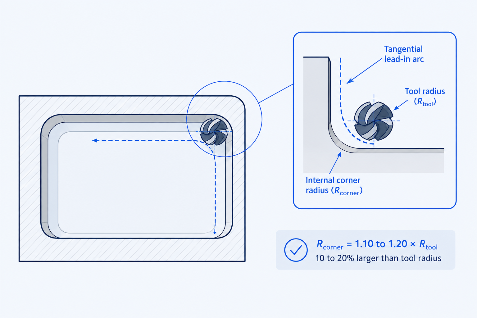
The rule is to design internal corners 10 to 20 percent larger than the cutting tool radius. A corner sized exactly to the tool wraps the cutter through more than 90 degrees of material at once, spiking cutting load and accelerating wear.
A clean wall also needs a tangential lead-in arc, where the tool curves onto the wall rather than approaching it straight on, since a straight approach leaves a witness mark at the point of contact. That lead-in arc needs a radius larger than the tool but smaller than the corner. A corner sized exactly to the tool radius leaves no room for the lead-in at all.
Add a small floor fillet
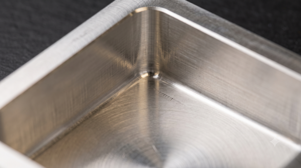
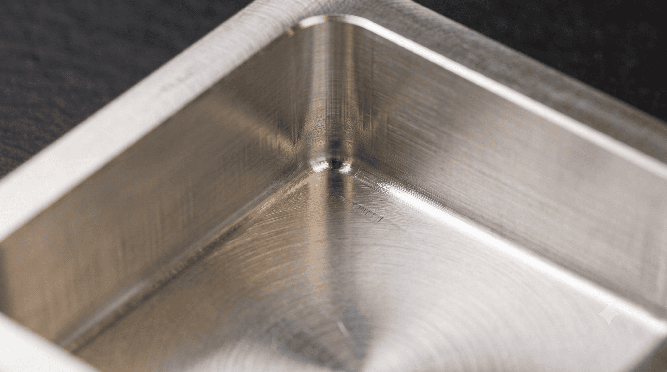
A perfectly sharp floor forces the use of a flat end mill, which wears fastest at its corner. Adding a small floor fillet, typically 0.5 to 1 mm, lets the shop run a bull-nose tool that finishes better and lasts longer. Floor corners are a separate decision from wall corners and are worth making deliberately.
Keep walls and floors thick enough to stay rigid
The part flexes as much as the tool does. A thin pocket floor or wall behaves like a drumhead under cutting pressure. A perfectly rigid tool can still produce a wavy floor if the material underneath it is vibrating. Minimum wall and floor thickness deserve the same attention as tool reach.
Material Behavior
Material has more influence on pocket milling cost and difficulty than any single dimension.
Material Machinability Snapshot Table
| Material | Relative Cutting Speed | Work Hardening Risk | Tool Change Frequency | Coolant Note |
| Aluminum | Fast | Low | Low | Flood coolant prevents flute welding |
| Mild / carbon steel | Moderate | Low to moderate | Moderate | Standard soluble coolant |
| Stainless steel | Slow to moderate | High | Moderate to high | Maintain constant chip load |
| Titanium | Slow | High | High | Low speed, high-pressure coolant |
Aluminum runs fast but can weld itself to the flute when chip evacuation or coolant application falls short. Stainless steel work-hardens, so a light cut can leave a harder surface for the next pass to face. Aluminum needs fewer tool changes and processes quickly. Stainless steel, and harder alloys like titanium, need slower speeds and more frequent tool changes.
Quick Reference Table
Design Choice Summary
| Design Choice | Easier to Machine | Difficult to Machine |
| Pocket depth vs. tool diameter | Up to 3x | Over 4x |
| Internal corner radius | 10 to 20 percent over tool radius | Sharp, or exact tool radius |
| Floor | Small fillet (0.5 to 1 mm) | Dead sharp |
| Sizing | Room for helical interpolation or ramping | Plunge or drill only |
| Boundary | Open | Fully enclosed and deep |
Tooling and Cutting Parameters
Tool selection
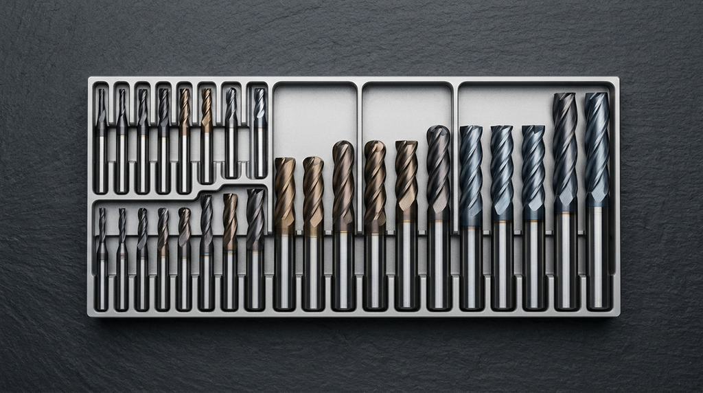
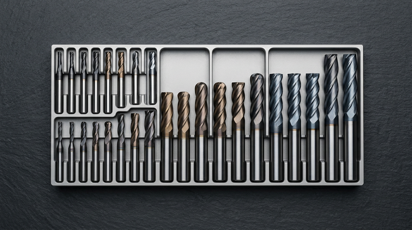
Aluminum takes 2- or 3-flute carbide end mills, whose wide flutes clear chips fast at high feed. Steel and tougher alloys take 4 flutes or more for rigidity and finish, at the cost of chip clearance room. Keep the tool length-to-diameter ratio under 4:1 wherever possible, since chatter becomes hard to control past that point. When depth forces a long tool, a neck-relieved long-reach design keeps a full-diameter shank for stiffness and thins only the necked section, unlike a plain end mill ground down its full length.
Feeds, speeds, and stepover
Reasonable starting points for conventional roughing are a 30 to 50 percent radial stepover, a 0.5 to 1x diameter axial step-down, and a 5 to 10 percent engagement finishing pass. Adaptive roughing departs from these figures entirely, running very low radial engagement at much deeper axial cuts.
One counterintuitive point matters here. When radial engagement drops below about 30 percent of tool diameter, feed needs to increase, not decrease. Below that threshold, the actual chip is thinner than the programmed feed per tooth, an effect called chip thinning. Without compensating, the tool rubs instead of cuts, heats up, and wears faster. Adaptive toolpaths rely on this relationship by design.
Finishing and achievable tolerance
Finish walls and floors as separate operations, since each wants a different tool and approach. Tight internal corners often need a rest or pencil pass with a smaller tool to clean out material the roughing cutter could not reach.
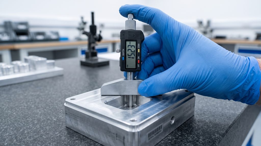
A well-set-up three-axis mill holds pocket dimensions to about plus or minus 0.05 mm without difficulty, roughly the ISO 2768-m general tolerance band. Tolerances tighter than that, down toward 0.01 to 0.025 mm, are achievable with light finishing passes, a rigid tool, and a shallow pocket. Still, every additional micron adds cycle time and inspection cost. Engineers evaluating whether a general tolerance callout is sufficient for a given pocket can check the ISO 2768 general tolerances calculator before tightening a callout.
A spring pass, a second finishing pass at the same programmed depth with no additional material removed, cleans up tool spring-back and brings a slightly undersized pocket to size. Specifying 0.01 mm on a wall that only needs 0.1 mm is one of the most common ways engineers add cost with no functional benefit.

Good Pockets Are Designed, Not Machined
A pocket’s cost and quality are decided mostly at the design stage, not on the CNC machine. Depth, corner radius, floor radius, enclosure, material, and tolerance are all design choices, and the shop lives with every one of them.
Round corners well past the tool radius, keep depth under about 3x diameter, fillet the floor, open the boundary when function allows, and reserve tight tolerances for surfaces that actually need them. Do that, and the programmer’s job stays simple, which is another way of saying cost-effective CNC machining.
Related Topics
 4
8
4
8






Comment(0)