

 Europe
  Türkiye
  United Kingdom
  Global





 Login with my Xometry account




This article covers the position tolerance, more formally known simply as “position” per ASME Y14.5, though “true position” remains the common industry term. Position is one of three location tolerances in the current standard, alongside concentricity and symmetry, both of which have been stripped from modern drawings due to measurement difficulty. Position, by contrast, is one of the most widely used GD&T controls, though it remains a common source of confusion for engineers new to GD&T.
What Is True Position?
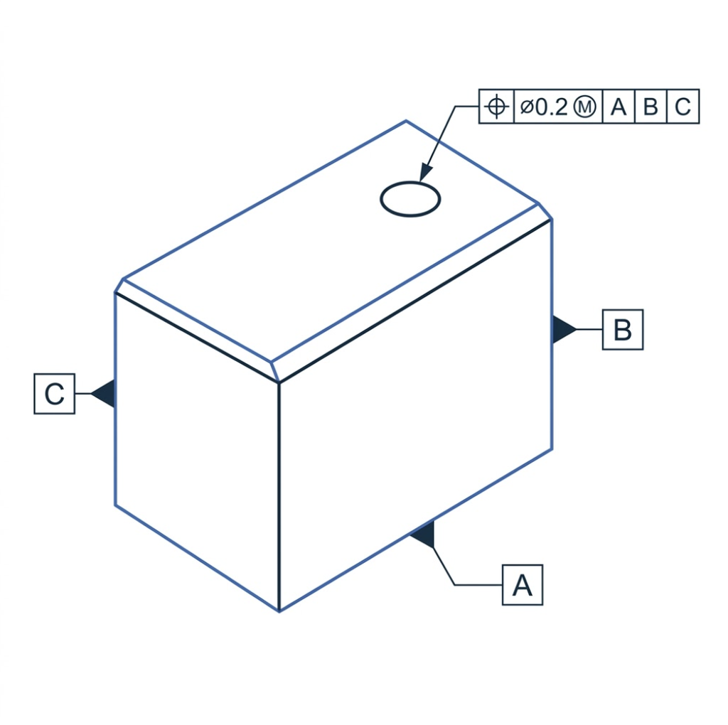
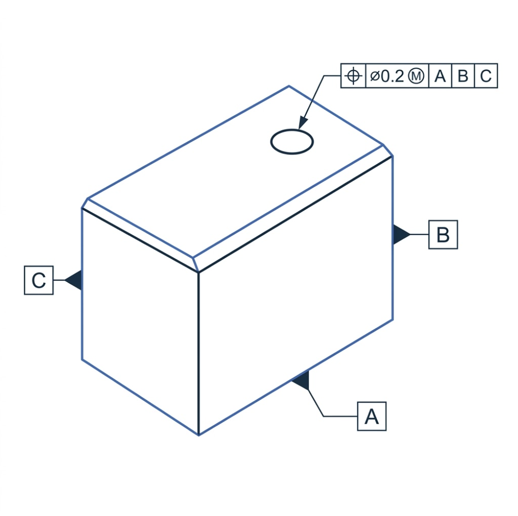
True position is a location tolerance that defines a zone within which a center, axis, or center plane of a feature of size is allowed to vary from a true, theoretically exact position. This ensures mating parts assemble correctly.
Two common ways to apply position are regardless of feature size (RFS) and under a material condition, either maximum material condition (MMC) or least material condition (LMC). Both are covered in detail below.
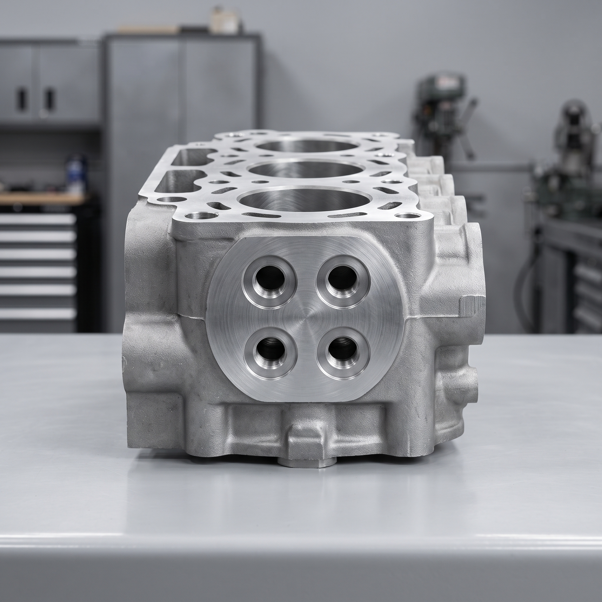
Real-world example: Cylinder head studs
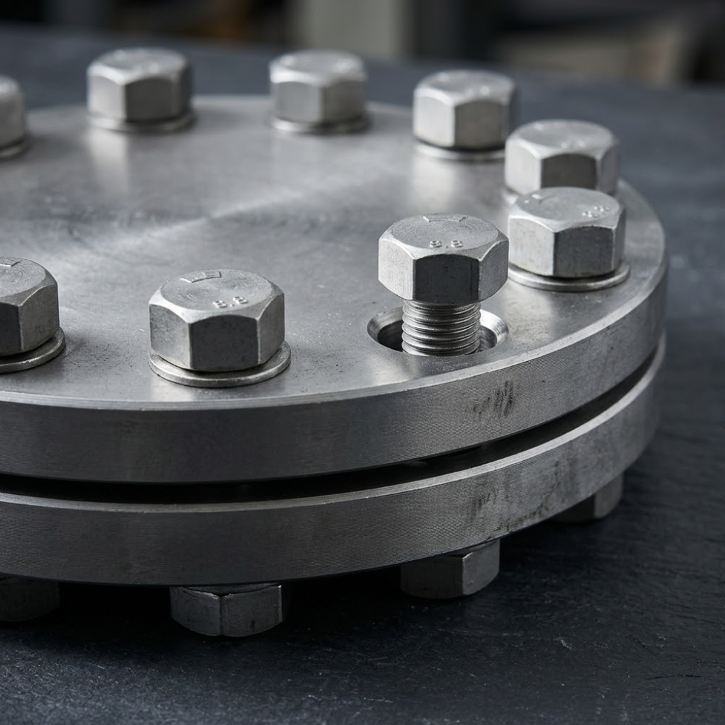
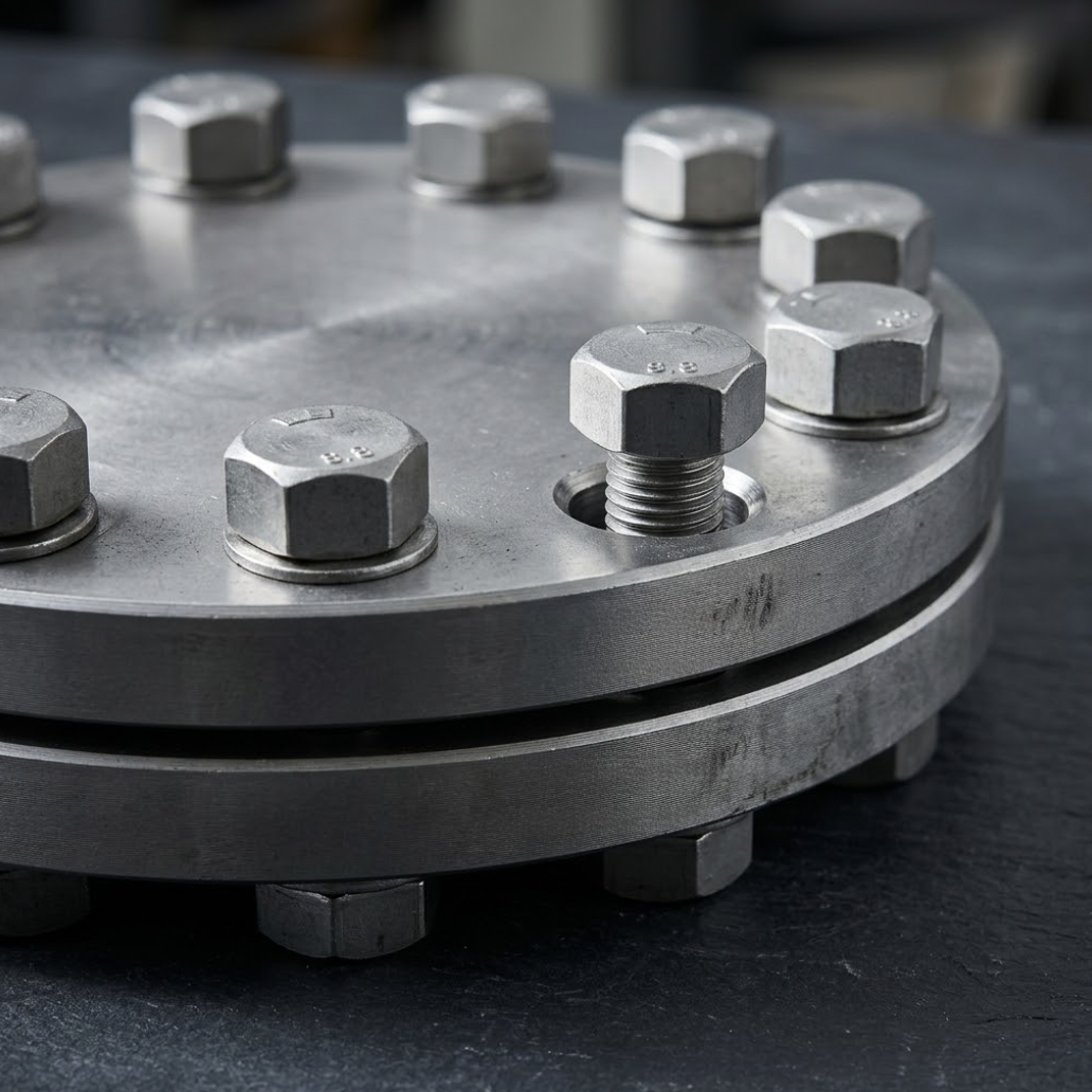
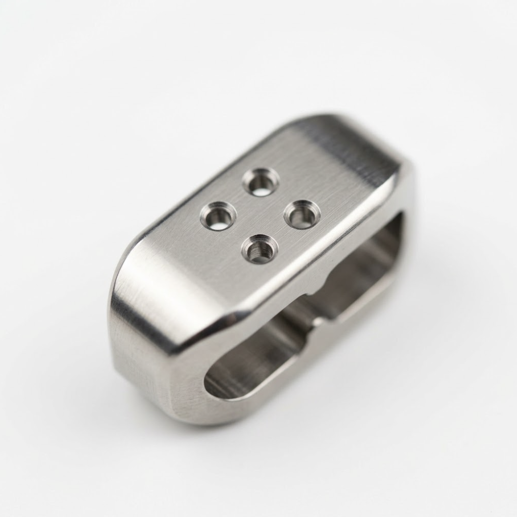
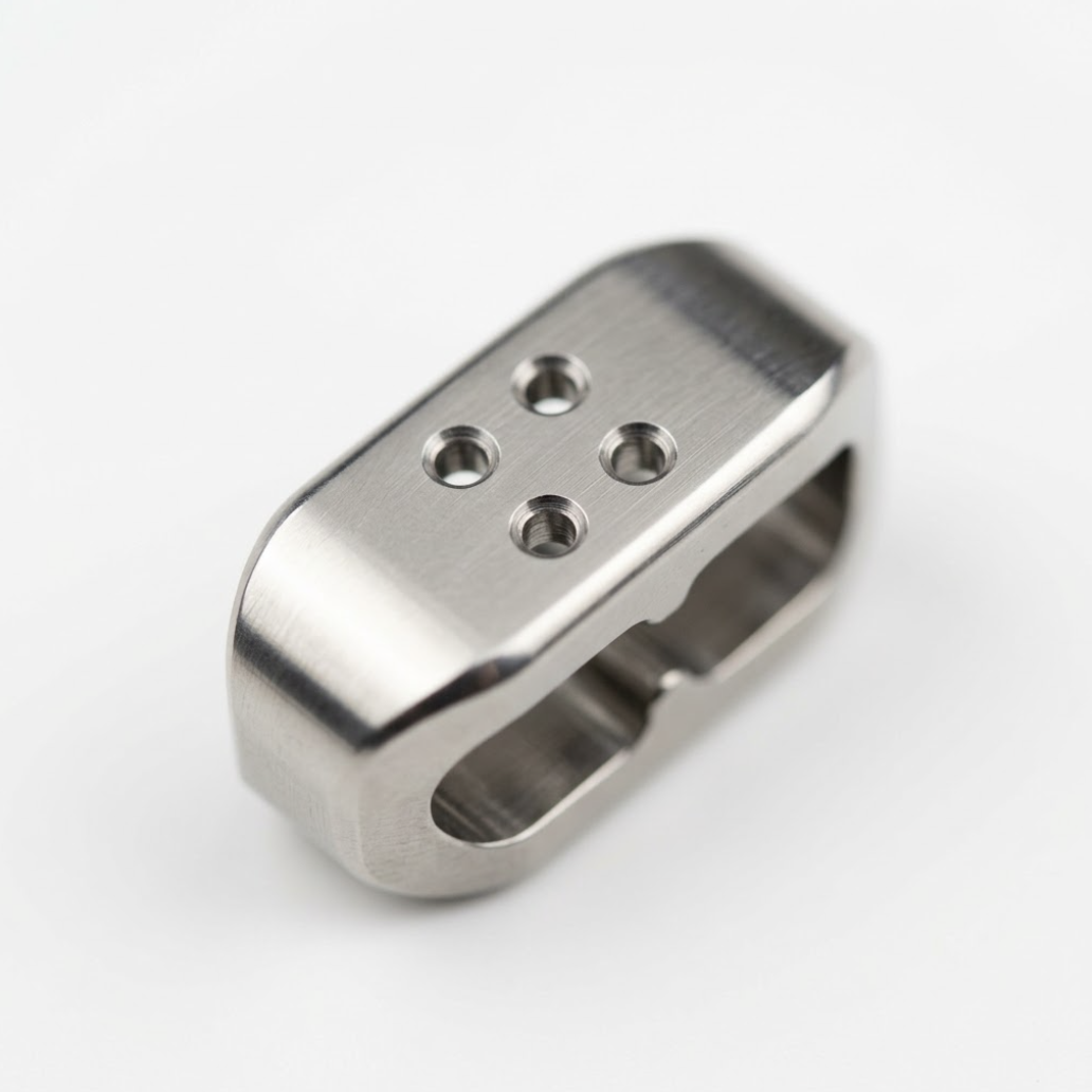
Consider cylinder head studs used to secure a cylinder cover to the engine casing in a Yanmar 8N21LEV marine engine. Four studs pass through the cylinder cover into the engine casing, threaded into the block or into threaded inserts.
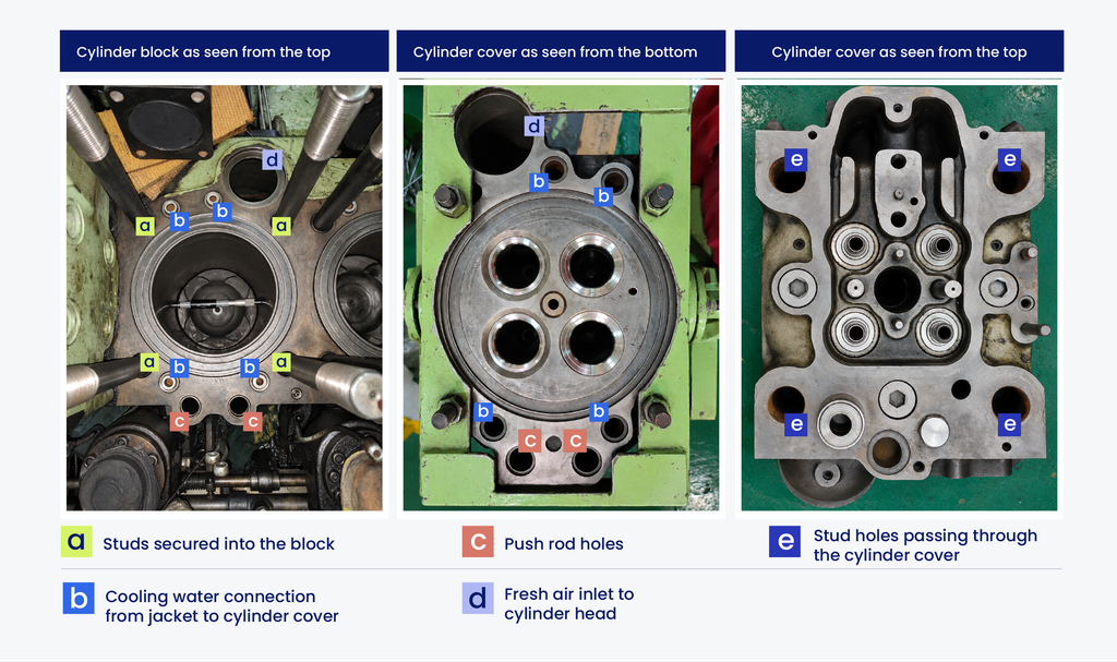
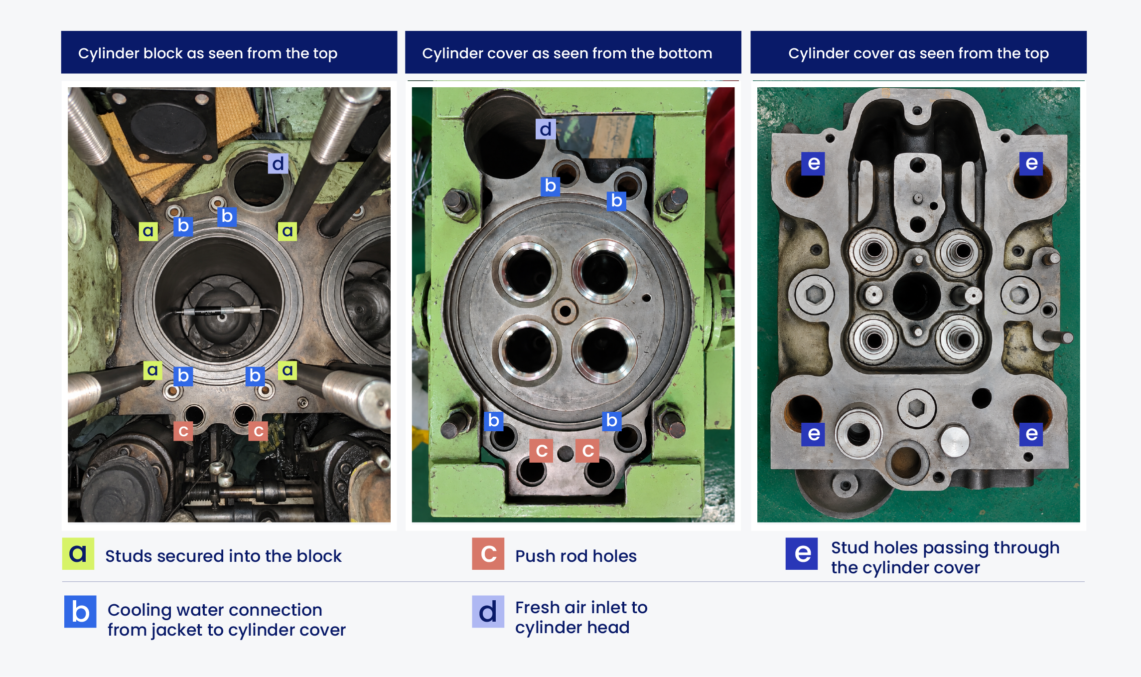
Simple coordinate tolerances could keep each hole within its own zone, but since each hole would be controlled individually rather than as a group, the overall stud pattern could still drift as a whole. As it deviates from the bore centerline, assembly fit suffers: difficult assembly, poor sealing of gases, coolant, or oil, bore misalignment, and uneven clamping force.
True position avoids this by locating all four stud holes relative to the cylinder bore’s axis, keeping the bore, stud holes, sealing surface, and coolant, air, and oil passages correctly related to one another. Correct assembly this way preserves sealing, balances load, and keeps cylinder covers interchangeable across the engine’s cylinder bank. For fastener-heavy assemblies like this one, the Bolted Joint Calculator can help verify clamping force once the stud pattern’s location is set.
True Position Tolerance Zone
The tolerance zone defines the allowable variation in a feature’s location. Position uses a three-dimensional tolerance zone that adapts its shape to the feature under control, taking one of two forms: a cylindrical zone or a rectangular zone made of parallel planes.
Cylindrical tolerance zone
The cylindrical zone suits features with a central axis, such as holes, pins, and shafts. It forms a cylinder around the feature’s basic axis, and the tolerance value equals that cylinder’s diameter. The feature passes when its derived axis lies entirely within the zone. A diameter symbol (∅) before the tolerance value signals a cylindrical zone, far more common in practice than the square alternative.
Position deviation for a cylindrical zone is calculated using the Pythagorean theorem:
TP = 2 × √(X² + Y²).
Rectangular or square tolerance zone
The rectangular zone, made of parallel planes, controls the center plane of non-cylindrical features like slots and tabs. The tolerance value is the distance between the planes, and the feature’s median plane must fall within them. Less common than the cylindrical zone, but fully supported under ASME Y14.5.
Position deviation for a rectangular zone is calculated as a simple linear value in each controlled direction independently, rather than combined into one radial value:
TP = 2 × |dX| and TP = 2 × |dY|.
True Position Feature Control Frame
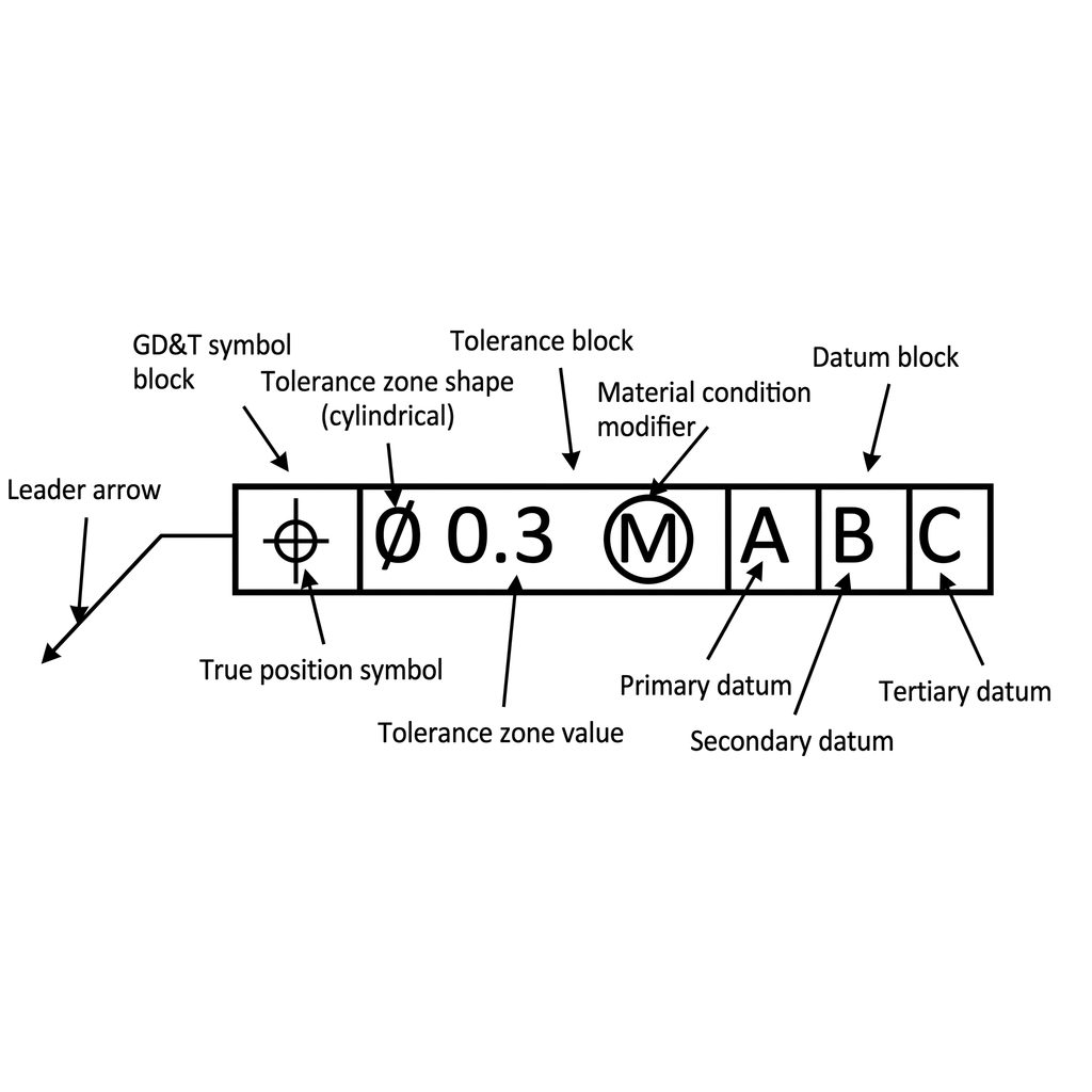
GD&T tolerances are denoted on an engineering drawing through a feature control frame, a standard layout of blocks providing all the information needed to define a tolerance completely. A general frame divides into three blocks: the GD&T symbol block, the tolerance block, and the datum block.
GD&T symbol block
The first block houses the standard symbol for the applied tolerance. For true position, this is a crosshair (⌖).
Tolerance block
The tolerance block defines the tolerance zone shape, its magnitude, and any material condition.
Tolerance zone shape. Cylindrical features use a cylindrical zone, denoted with a diameter symbol (∅). Non-cylindrical features like slots and tabs use the default parallel-plane zone instead, with no dedicated symbol.
Tolerance value. For a cylindrical zone, this is the zone’s diameter, and the feature’s actual axis must fall within it. For a parallel-plane zone, it’s the distance between the planes, and the median plane must fall within them.
Material condition modifier. Position is often applied at MMC or LMC, shown as a circled M or L. No symbol means the tolerance applies regardless of feature size (RFS). A material condition also unlocks bonus tolerance as the feature’s size departs from it.
Datum block
Position specifies a feature’s location relative to a datum, defined in the datum block, which can be a surface, axis, or center plane. Multiple datums, typical for position, are listed in decreasing order of importance, most often as three mutually perpendicular primary, secondary, and tertiary datums.
Bonus Tolerance
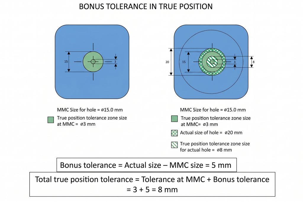
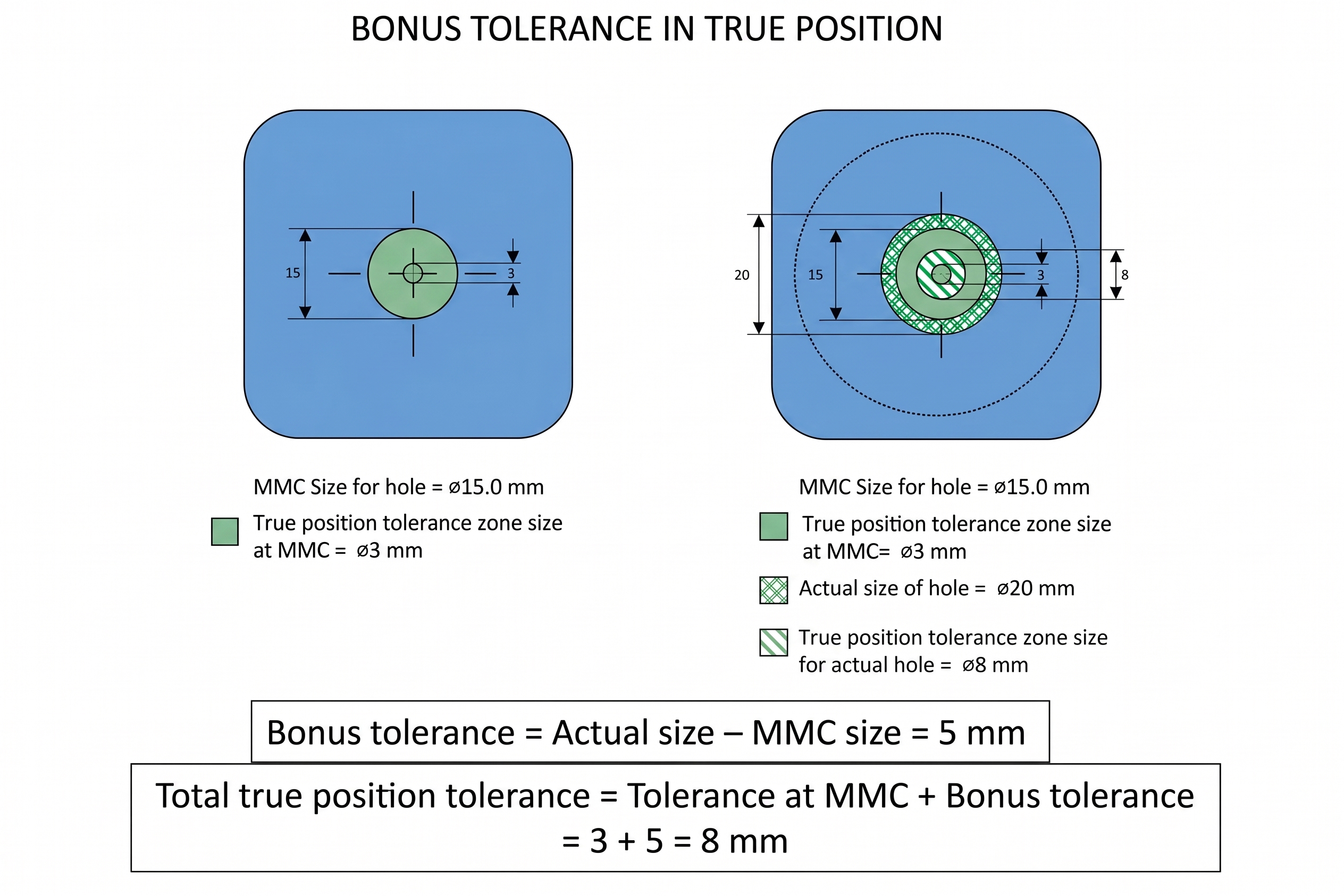
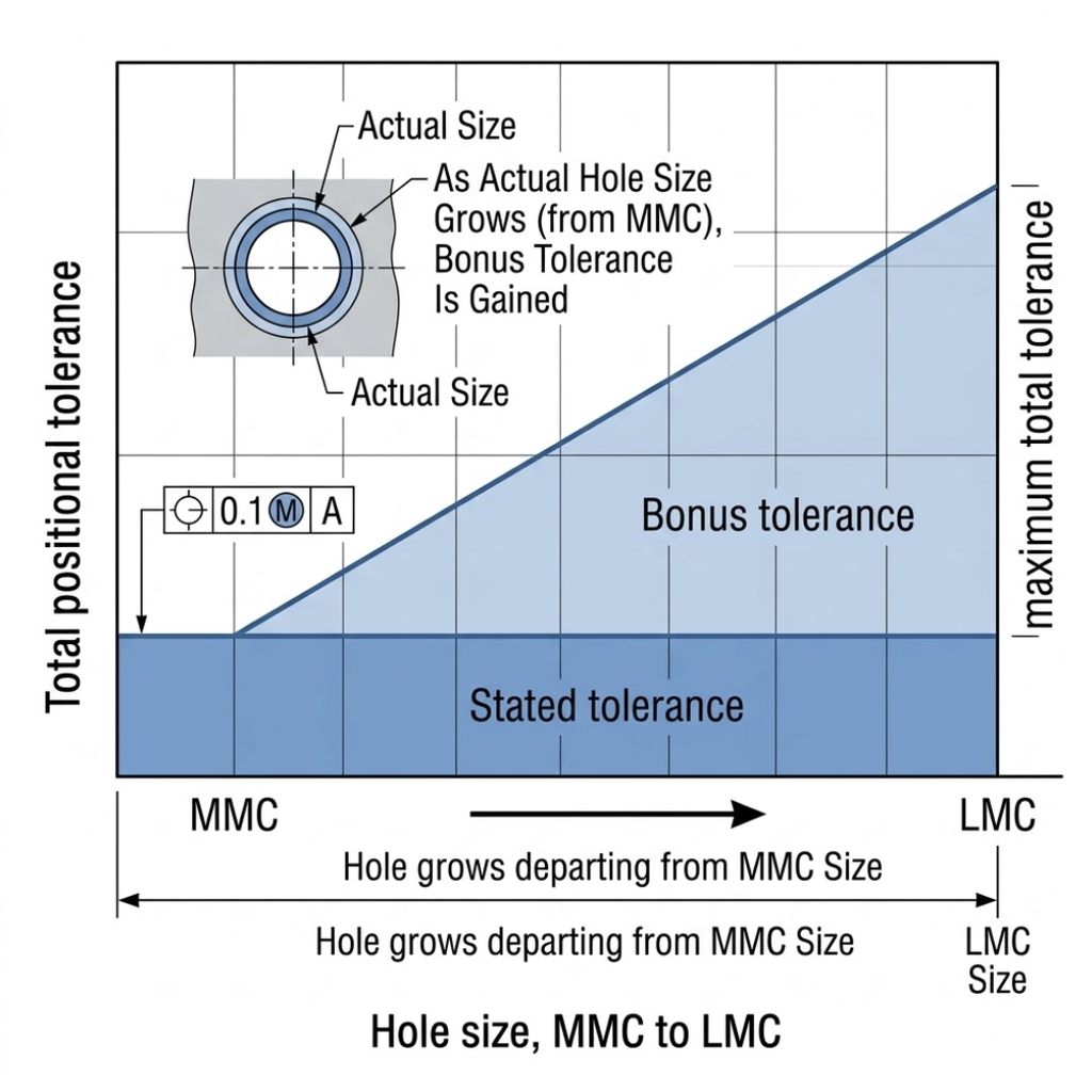
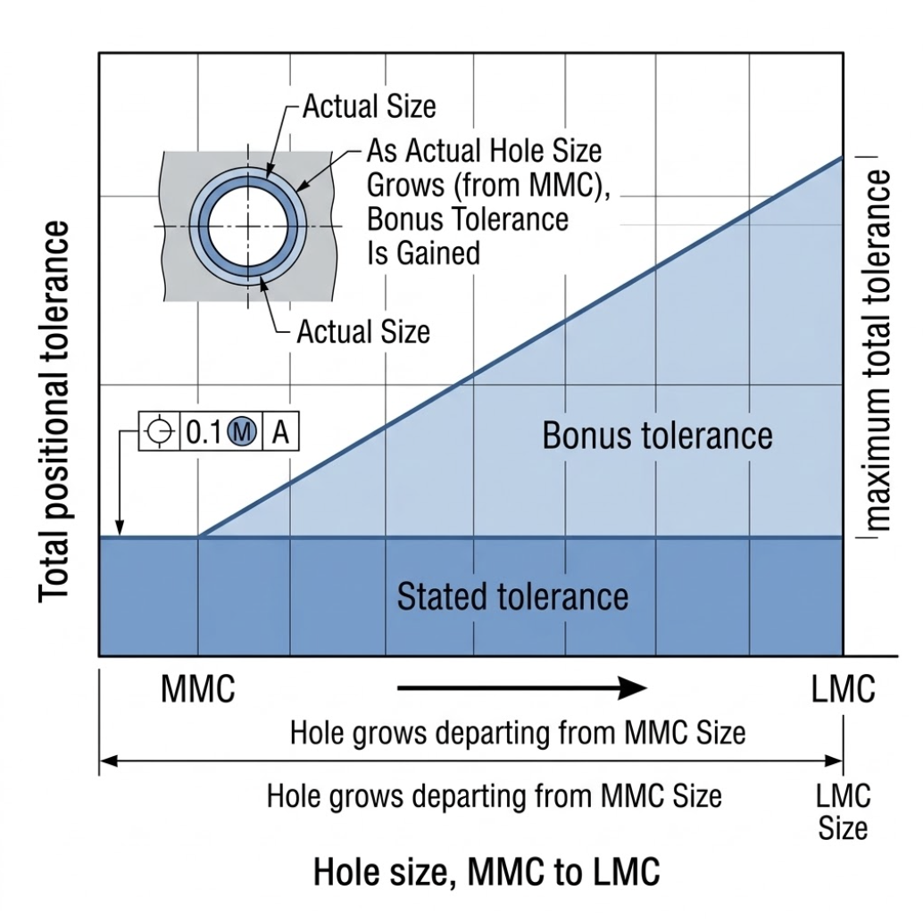
Bonus tolerance is one of the biggest advantages of applying position with a material condition: a feature gains additional tolerance as it departs from MMC size, making the part cheaper to manufacture while still guaranteeing assembly. It adds directly to the tolerance stated in the feature control frame.
Consider a stud hole toleranced to 26 ± 0.2 mm. The hole can range from 25.8 mm at MMC to 26.2 mm at LMC. A position tolerance of 0.3 mm is applied at MMC.
Bonus Tolerance Example
| Condition | Hole Size | Positional Tolerance |
| At MMC | 25.8 mm | 0.3 mm (no bonus) |
| At LMC | 26.2 mm | 0.7 mm (0.3 mm stated + 0.4 mm bonus) |
A larger hole provides more clearance around the stud, letting it sit slightly farther from its true position without affecting assembly, so larger holes gain more positional freedom. The same logic applies in reverse to external features like pins and shafts.
Bonus tolerance brings several practical benefits: easier machining, guaranteed assembly, higher manufacturing yield, lower scrap rate, and fewer inspection rejects.
Without a material condition modifier, position applies regardless of feature size (RFS), and the tolerance stays fixed across the feature’s entire size range. This matters when location is critical regardless of size: an oversized injector hole will still hold the injector, but its axis must stay precisely located to the cylinder’s axis. Other common RFS applications include motion and alignment features, bearings, journals, and metrology datums.
In practice, use MMC when greater clearance justifies additional positional tolerance, and RFS when feature location matters more than size variation. This is why fastener holes are typically controlled with MMC, while precision features like dowel pins, bearing bores, and injector holes are usually controlled with RFS.
True Position vs. Other Tolerances
True position is used extensively to control feature location across nearly every drawing, but it shares enough surface similarity with other tolerances to cause judgment errors in choosing which to apply.
True Position vs. Linear Tolerancing
| Aspect | True Position | Linear (Coordinate) Tolerancing |
| Tolerance zone shape | Circular or cylindrical, uniform radial control | Rectangular, non-uniform radial limits |
| Datum reference | Explicit, well-defined datum reference frame | Often implied, ambiguous origin |
| Bonus tolerance | Available with MMC or LMC modifiers | Not available |
A true position tolerance of ⌀0.2 mm creates a circular zone with the same 0.1 mm deviation allowed in every direction. A linear tolerance of X ±0.1 mm and Y ±0.1 mm instead creates a rectangular zone whose corners sit 0.141 mm from center, farther than the 0.1 mm allowed at the edges, letting features with greater radial error pass. This is a main reason position is preferred for holes, pins, and other assembly-critical features.
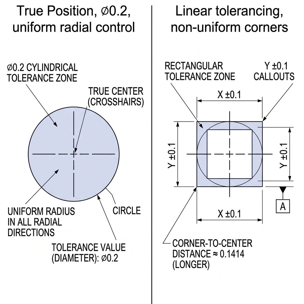
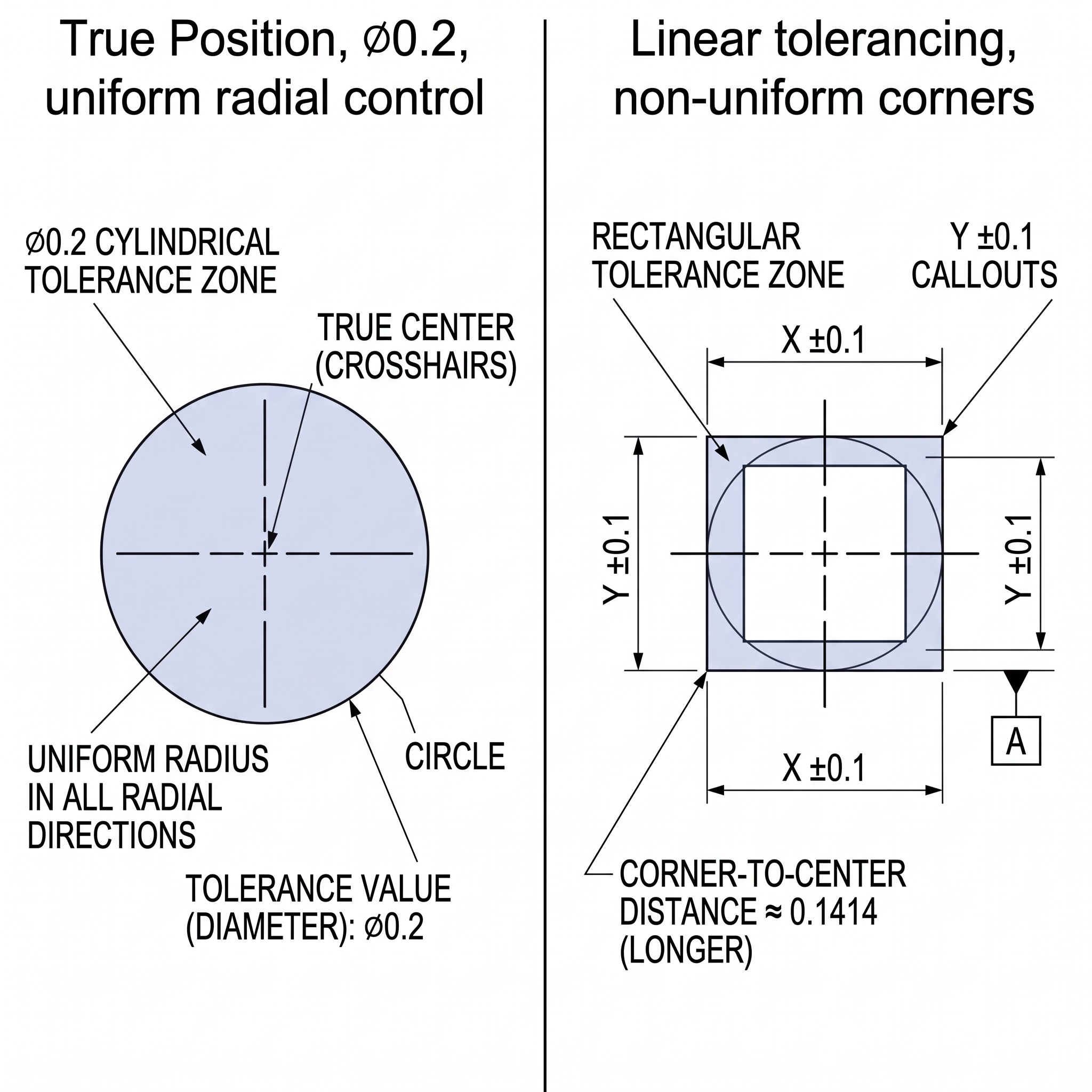
Linear tolerancing also often relies on implied datums, creating ambiguity about where a measurement originates, while position uses explicit datums for accurate location and inspection. And unlike linear tolerancing, position gains bonus tolerance under a material condition modifier, improving manufacturability and inspection efficiency at no cost to assembly.
True Position vs. Related GD&T Callouts
| Callout | Category | Controls | Requires Material Modifier Support | Ease of Inspection |
| True position | Location | Axis, center, or center plane location relative to true position | Yes (MMC, LMC, RFS) | Moderate, functional gauges available |
| Concentricity | Location (legacy) | Median point distribution about a datum axis | No, always RFS | Very difficult, typically CMM only |
True position vs. concentricity
Many engineers have historically used concentricity where true position would be the better choice. Concentricity controls the median points of diametrically opposed surface elements relative to a datum axis, mainly relevant to dynamic balance and mass distribution.
Where high speed, balancing, and vibration aren’t a concern and the goal is just functional assembly, true position is the better tool: it locates a feature’s axis without regard to its form, and it’s far easier to inspect, functional gauges verify it quickly, where concentricity almost always needs a CMM.
Concentricity was removed from ASME Y14.5-2018 for frequent misinterpretation, measurement difficulty, and limited functional purpose. True position or total runout can replicate the same intent, depending on what the design actually needs.
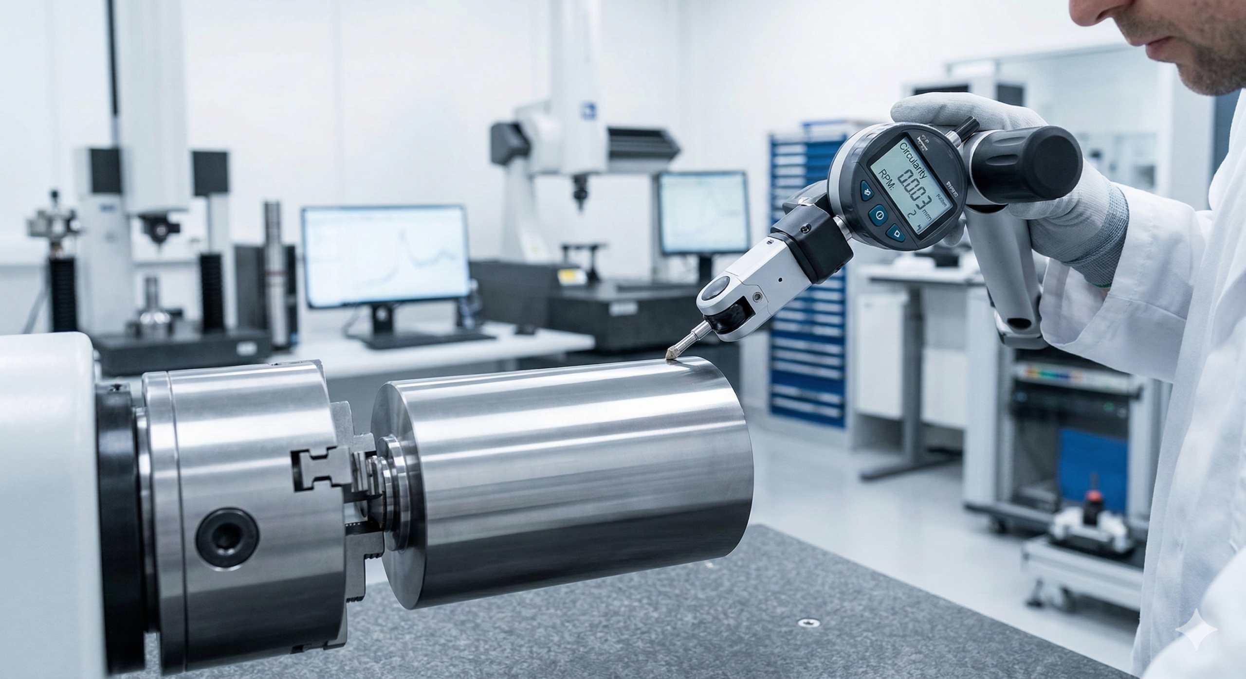
How to Measure True Position
Position can be measured with methods ranging from simple shop-floor checks to advanced automated systems. The right choice depends on accuracy needed, production volume, part geometry, and whether a pass/fail result or a numeric value is required.
True Position Measurement Method Comparison
| Method | Output Type | Accuracy | Best Use Case |
| Functional gauge (go/no-go) | Pass or fail only | Not applicable | High-volume production, fast floor checks |
| Surface plate with dial indicator | Numeric | Moderate | Low-cost, simple parts, small setups |
| Coordinate measuring machine (CMM) | Numeric, automatic MMC/LMC/RFS calculation | High | Complex datum schemes, high accuracy |
| Portable measuring arm | Numeric | High | Large or immovable parts, engine blocks |
| Laser scanning | Point cloud vs. CAD comparison | Moderate to high | Complex geometry, non-contact measurement |
Functional gauging
Functional gauges are effective for quick floor inspections. Each is a template built at the feature’s virtual condition; a part passes if it fits.
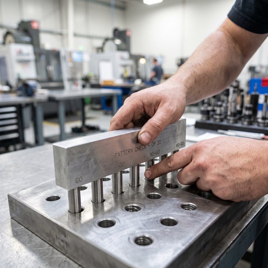
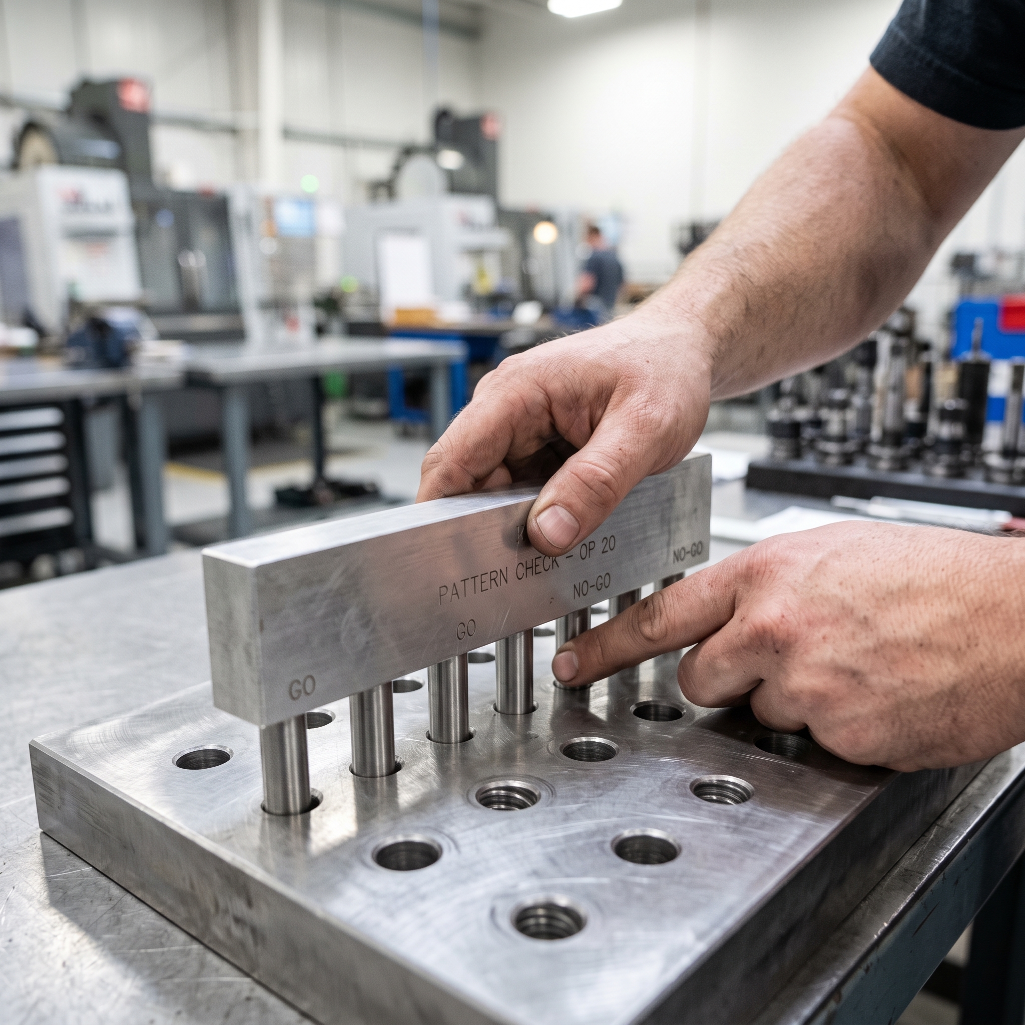
Gauges give no numeric error value, but their speed suits high-volume production and they verify assembly function directly. They don’t apply to RFS callouts.
Surface plate
A surface plate paired with a dial indicator or height gauge establishes datums manually, then measures X and Y coordinates to calculate positional error. It’s low-cost and suits small setups, though time-consuming and limited to simple parts. Pairing dial indicators with dedicated fixtures speeds this up for higher-volume production.
Coordinate measuring machine
A CMM aligns the part to its datum reference frame, probes the feature’s actual position, and compares it against the ideal position to calculate deviation. It offers high accuracy and automatic error calculation across MMC, LMC, and RFS, though it stays vulnerable to surface irregularities and programming errors.
Portable measuring arm
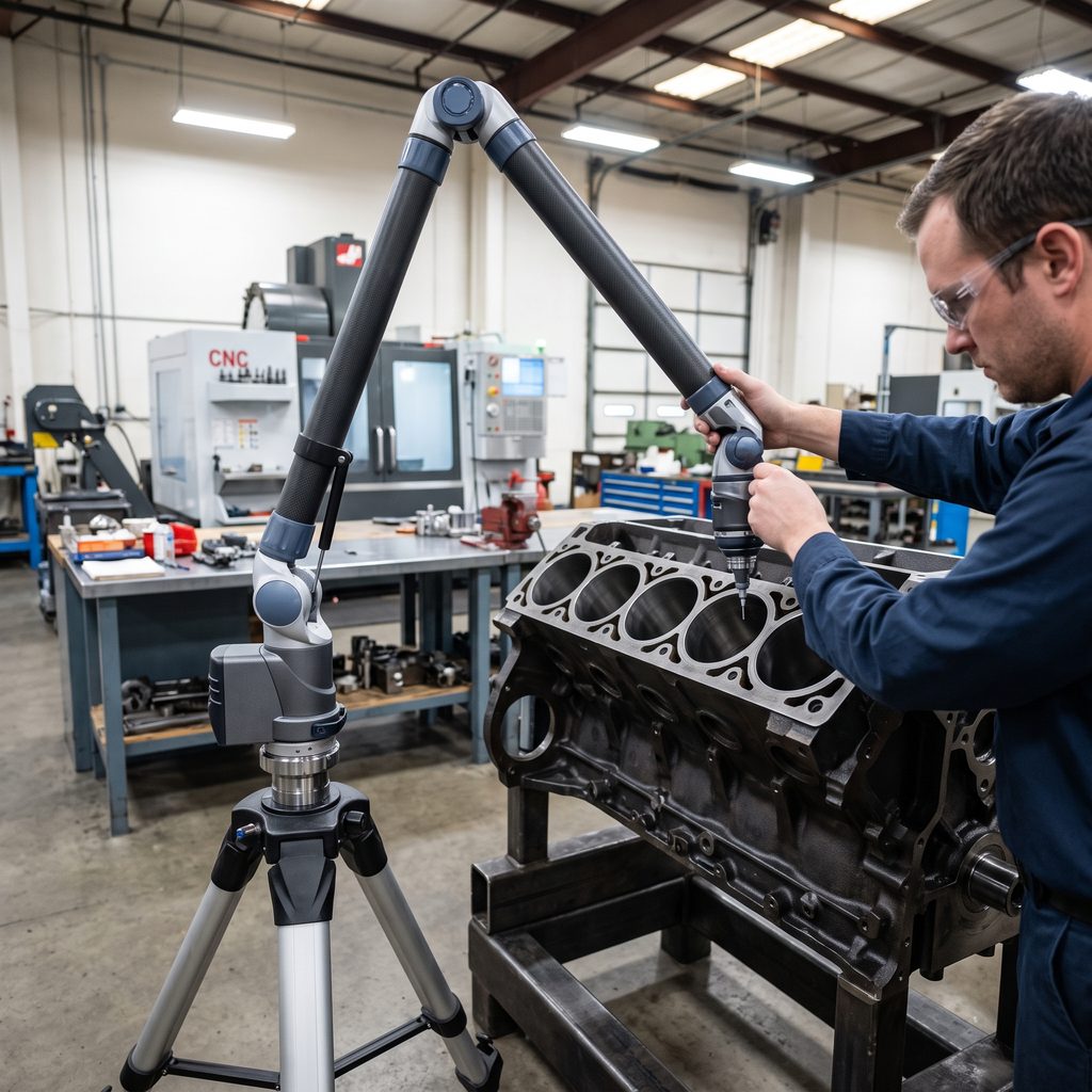
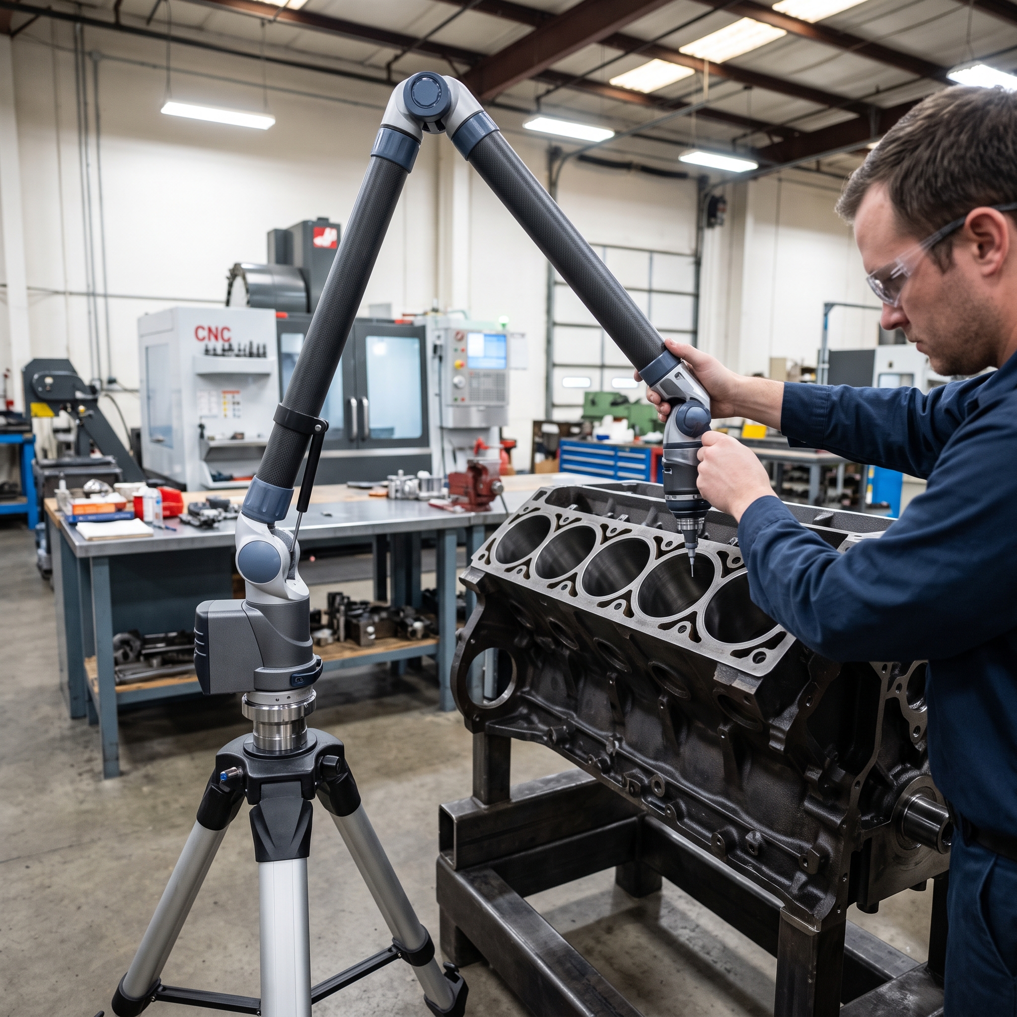
A portable measuring arm works like a CMM but suits large or heavy parts that can’t be moved to a fixed machine, commonly used on engine blocks and marine engine components.
Laser scanning
Laser scanning is non-contact, building a dense point cloud that software compares against the CAD model, accounting for material modifiers where relevant. It suits complex parts like turbine blades and medical implants, but is less accurate than a CMM and sensitive to reflective surfaces and line-of-sight occlusion.
Conclusion
True position appears on nearly every GD&T drawing because it addresses the fundamental need to precisely locate part features. Defining a tolerance zone around a true position, rather than relative to adjacent features, ensures features land where they need to be and mate as intended.
Unlike coordinate tolerancing, position provides a well-defined datum reference frame, avoids tolerance accumulation, and can use bonus tolerance when applicable, delivering better manufacturability, lower scrap rate, and simpler inspection. For engineers working across the rest of the location and orientation family, the GD&T technical library on Xometry Pro also covers concentricity, perpendicularity, and angularity.
Related Topics
 2
2
 Javier López Picazo
2
Javier López Picazo
2





Comment(0)