select
navigate
switch tabs
Esc close

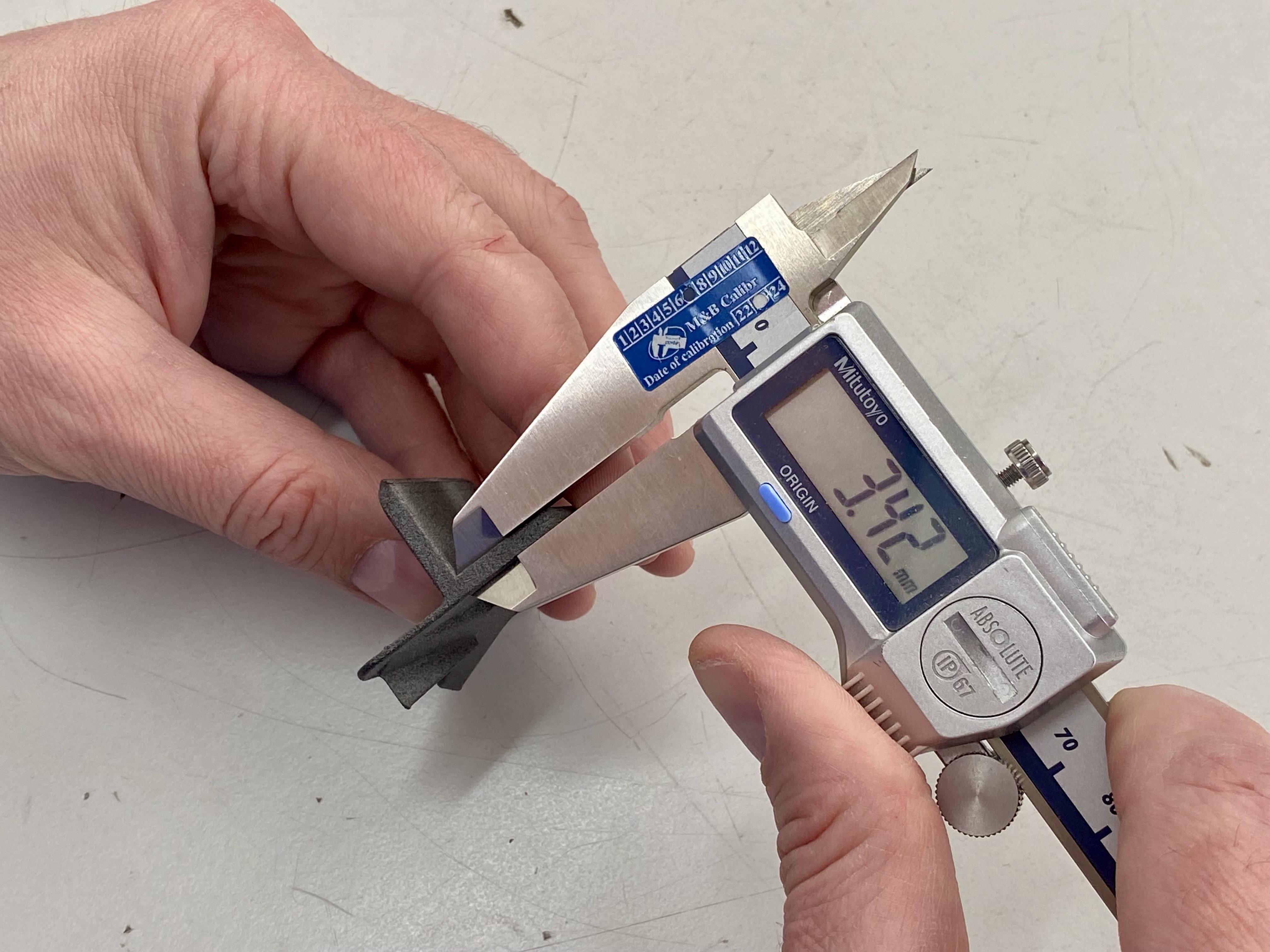
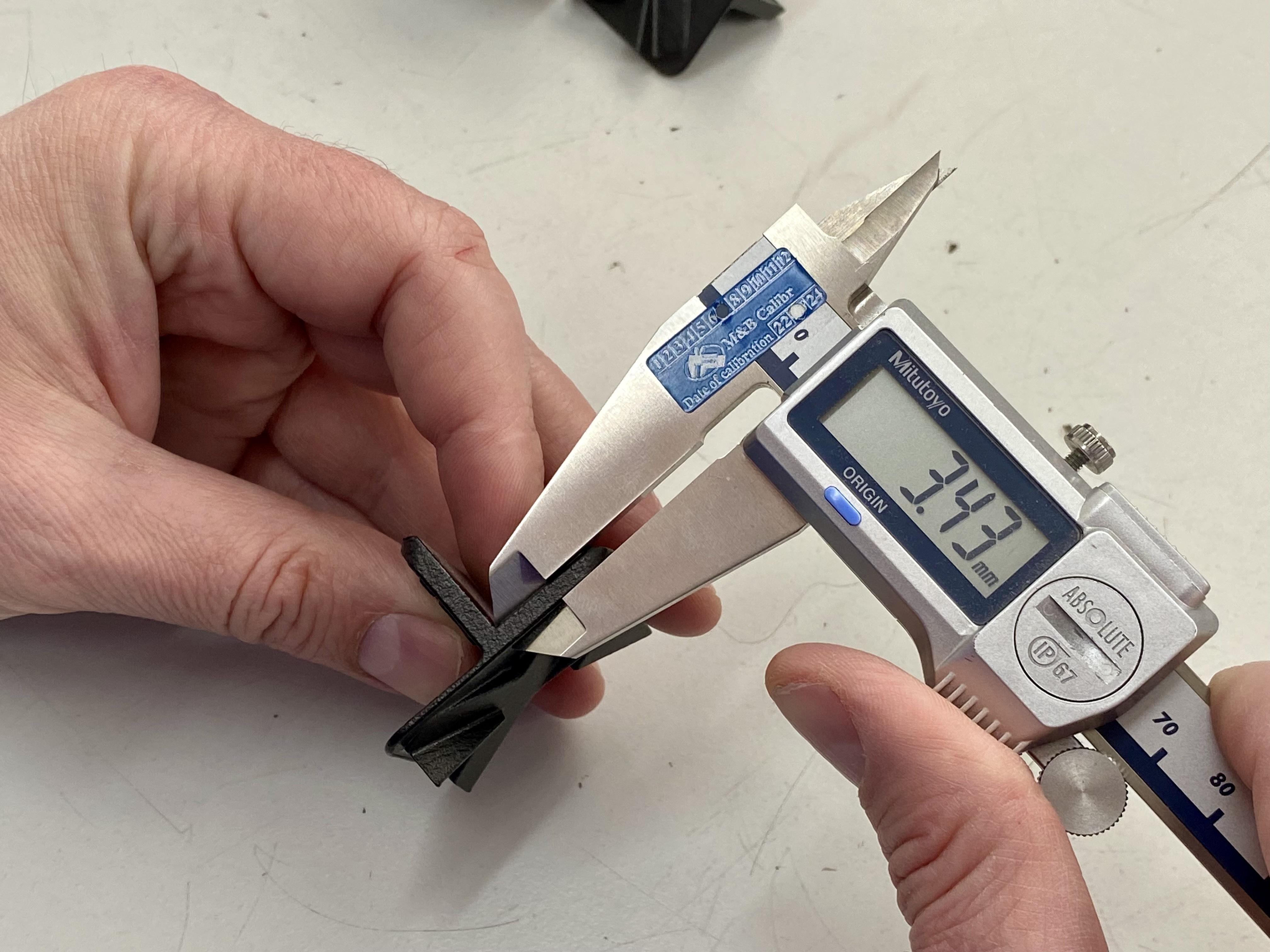
How does vapor polishing effect 3D prints' tolerance?

0
D
8

Hi everyone,

I’m exploring vapor polishing for PA11 SLS parts. Concerned about how it might affect part tolerance and dimensional accuracy. Does anyone have insights or experiences on the dimensional changes to expect for PA11/PA12 (SLS or MJF 3d printing)? Tips on maintaining tight tolerances while improving surface finish would be great too!

Thanks in advance!

Solved by Evgeny Misnikov

Hello, Daan! Great question –

Just a quick addition here: I also had a quick check of a few parts we have in stock at the Xometry office: We measured the dimensions of a few identical MJF PA12 parts as printed vs vapor polished ones with a digital caliper, and we didn’t see any substantial differences outside of the regular dimensional accuracy ranges of MJF (±0.2 mm up to 100 mm and 0.2% above that value). Attaching a couple of pics for reference, but we overall compared 8 different samples  

    • D

      Hi everyone,

      I’m exploring vapor polishing for PA11 SLS parts. Concerned about how it might affect part tolerance and dimensional accuracy. Does anyone have insights or experiences on the dimensional changes to expect for PA11/PA12 (SLS or MJF 3d printing)? Tips on maintaining tight tolerances while improving surface finish would be great too!

      Thanks in advance!

      0
    • Xometry Engineer

      Hello Daan,

      It’s fantastic to see you venturing into vapor polishing for SLS parts. This process can indeed enhance the surface finish of PA11 and PA12 parts, making them smoother and more aesthetically pleasing. Given your concern about maintaining dimensional accuracy, here’s what you need to know:

      Understanding Dimensional Changes:

      • Vapor polishing works by slightly melting the outer surface of the part, smoothing it in the process.
      • PA11 and PA12, being semi-crystalline polymers, are susceptible to minor dimensional changes due to this outer layer alteration.
      • Typically, the change is in the range of a few microns but can vary based on the part’s geometry and the exact conditions of the vapor polishing process.

      Tips for Maintaining Tight Tolerances:

      1. Test and Measure: Before proceeding with production parts, test the vapor polishing process on a few sample parts. Measure these pre- and post-polishing to understand the average dimensional change you can expect.
      2. Adjust Part Design: If you consistently see a certain degree of shrinkage or dimensional change, consider adjusting your part designs to compensate.
      3. Controlled Environment: Ensure the vapor polishing process is conducted in a controlled environment, with consistent temperature and exposure time to minimize variations.
      4. Layer Thickness Consideration: Parts printed with finer layer thickness might show less noticeable changes after vapor polishing due to their already smoother surface.
      5. Post-Process Measurement: Always measure your parts after vapor polishing to ensure they still meet the required tolerances. Consider using this data to further refine your process.

      Experiences with PA11/PA12:

      • Both materials are known for their durability and flexibility, which is retained after vapor polishing.
      • Dimensional changes are typically minimal but more noticeable on edges or thin features.
      • Anecdotally, some have reported up to a 0.5% change in dimension, though this is highly dependent on part design and polishing conditions.

      Conclusion: Vapor polishing can significantly improve the surface quality of PA11 and PA12 parts. By carefully controlling the process and adjusting for any dimensional changes, you can maintain tight tolerances while achieving a superior finish. As always, experimentation and precise measurement are key to refining your approach. Should you have further questions or need more detailed advice, feel free to reach out. Happy to help you navigate these advanced finishing techniques.

      Best wishes, Attila

      2
      Reply
      2
      • Admin
        Attila Szucs

        Hello, Daan! Great question –

        Just a quick addition here: I also had a quick check of a few parts we have in stock at the Xometry office: We measured the dimensions of a few identical MJF PA12 parts as printed vs vapor polished ones with a digital caliper, and we didn’t see any substantial differences outside of the regular dimensional accuracy ranges of MJF (±0.2 mm up to 100 mm and 0.2% above that value). Attaching a couple of pics for reference, but we overall compared 8 different samples  

        4
        Reply
        4
      • D
        Attila Szucs

        Thank you for the info!

        0
        Reply
    • Senior Content Manager

      Hi Daan, to give you a comprehensive overview, I also recommend checking out a video we’ve created on vapor smoothing. It’s quite informative and visually demonstrates the process and its effects on 3D printed parts. You can watch it here: https://youtu.be/1LoPp8gc5yI?si=O8LgbiTRYpdwsAW9

      We also ran a few experiments on 3D prints and it turned out that you can achieve a much smoother surface without affecting the parts’ dimensional accuracy with vapor smoothing. We have an in-depth article on this finishing process, you can have a look here: https://xometry.pro/en-eu/articles/3d-printing-vapor-smoothing/

      0
      Reply
How does vapor polishing effect 3D prints’ tolerance?
Your information:


Suggested Topics

Topic
Replies
Views
Activity
Embossed vs. engraved text for outdoor molded parts
Hi there, I need to add a part number and recycling symbol on the surface of molded parts in PP GF20 for outdoor use. I initially planned to use engraved text for aesthetic reasons,... read more
T
0
14
Jul 25
Minimum hole diameter vs sheet thickness 316L
Hello, I would like to produce a stainless steel 316L bracket, 3 mm thick, cut by fiber laser. I need to include several small holes for drainage and fastening, and I’ve heard there might... read more
F
A
1
25
Jul 25
Ejector pin placement near snap-fit
I’m working on a small injection-molded housing for an automotive sensor, using PA6 GF30. There are two snap-fit arms inside (cantilever type), about 2 mm-thick walls. I’m not sure where to place the ejector... read more
M
T
5
102
Jul 18
Adding countersinks to formed stainless sheet metal
Hello, I'm working on a sheet metal enclosure (as in the image) that requires flush mounting for M6 countersunk screws. I need to add a countersink on a few holes, but the part is... read more
D
M
D
2
109
Jul 03
Fastener size choice for a through-hole in 4 mm anodized aluminum plate
Hi! Designing a lightweight enclosure for a small UAV component, using 4 mm thick anodized aluminum sheets. For the assembly, I need to fasten this plate to a 3D-printed ABS bracket underneath, which acts as... read more
K
e
E
3
230
Jun 30