 Europe
  Türkiye
  United Kingdom
  Global


 0
0

Within this system, Flatness is a fundamental Form Control used to define the straightness of a surface across a 2D plane. The form tolerances consist of shape controlling callouts like straightness, flatness, circularity and cylindricity in geometric dimensioning and tolerancing.
Unlike location or orientation controls, form controls do not require a datum reference; they apply strictly to the shape of the feature itself.
What is Flatness in GD&T?
The Flatness tolerance controls the planarity of a surface. It defines a tolerance zone consisting of two parallel planes spaced apart by the tolerance value. All points on the actual surface must lie entirely within these two planes.
The tolerance zone floats freely. The planes do not need to be parallel to any other surface or datum; they are defined solely by the surface being controlled.
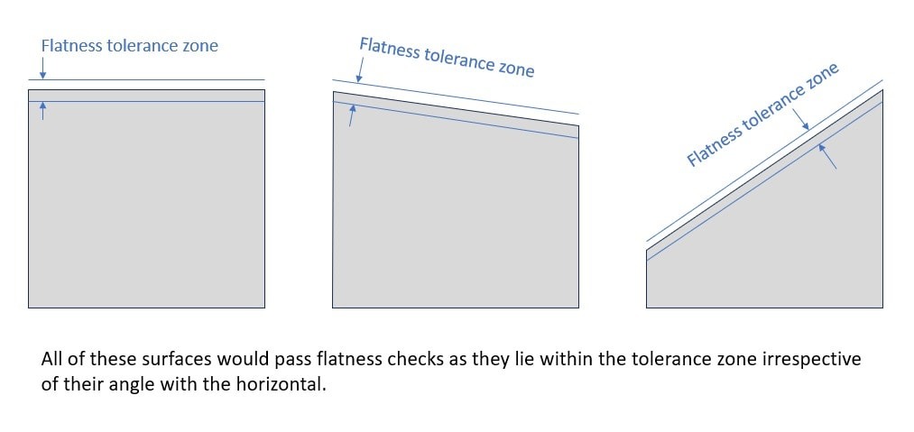
Flatness tolerance defines how flat a surface is, ensuring the surface’s highest and lowest points stay within the specified tolerance zone.
The flatness callout may also be used to control, manufacture and inspect a feature of size[1]. In this case, the callout actually measures the deviation of the derived median plane[2].
Flatness is primarily used to control reference (datum) surfaces or to increase the precision of other tolerances, allowing critical mating surfaces to maintain proper sealing, lubrication, stress concentration, and load distribution without tightening size tolerances.
Feature Control Frame for Flatness Tolerance
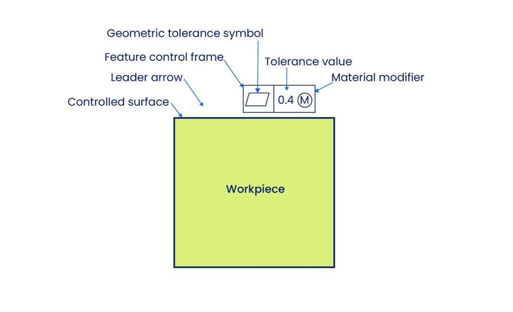
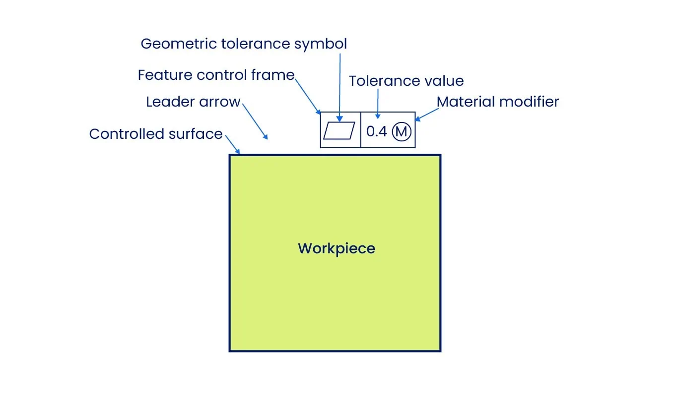
The feature control frame (FCF) for Flatness is a rectangular box divided into specific compartments that define the tolerance requirements.
- First Compartment (Symbol): Contains the geometric characteristic symbol. For flatness, this is a parallelogram.
- Second Compartment (Tolerance Value): Specifies the total allowable variation. This numerical value defines the distance between the two parallel planes of the tolerance zone.
- No Datum Reference: Since Flatness is a form control independent of other features, there is no third compartment for a datum reference.
Leader Arrow Placement The placement of the leader arrow is critical for interpretation:
- Surface Control: When the arrow points to the surface or its extension line, the tolerance controls the surface itself.
- Derived Median Plane: When the arrow points to the size dimension, the tolerance controls the Derived Median Plane (the center plane of the feature).
Design Tip: Always maximize the tolerance value as much as functionality permits. Unnecessarily tight flatness tolerances require expensive machining and inspection processes (e.g., grinding or lapping) which significantly increase part cost.
Flatness vs Other Tolerances
Flatness is often confused with straightness, parallelism, and surface finish. Understanding the distinction is vital for selecting the correct callout.
Flatness vs Straightness
Flatness is the 2D version of the straightness tolerance. While straightness tolerance creates a tolerance zone with two parallel lines, the flatness tolerance zone consists of two parallel planes, enabling it to control a 2D surface instead of a 1D line.
Use Straightness to control the « waviness » of a shaft or a single line on a block. Use Flatness to control the peaks and valleys of an entire table top or sealing face.
Flatness vs Parallelism
The primary difference between these two controls is the requirement for a datum. Parallelism controls the orientation of a surface relative to a specific datum reference, ensuring one plane remains equidistant from another. Flatness is an independent requirement that controls the form of a single surface without regard to any other feature.
Use Flatness when a surface must be planar but its angle relative to the rest of the part does not matter (e.g., a standalone reference plate). Use Parallelism when the surface must be perfectly aligned with an opposing face or mounting plane (e.g., a table top parallel to the floor).
Flatness vs Surface Finish
While both terms describe surface quality, they operate at different scales. Flatness controls macro-level deviations such as bowing, warping, or twisting. Surface finish measures micro-level irregularities, specifically the roughness of the texture. A part can be perfectly flat but rough, or mirror-polished (smooth) but warped.
Use Flatness to ensure parts fit together correctly during assembly. Use Surface Finish to control subtler interactions like friction, wear rates, and sealing tightness.
How to Measure Flatness Tolerance
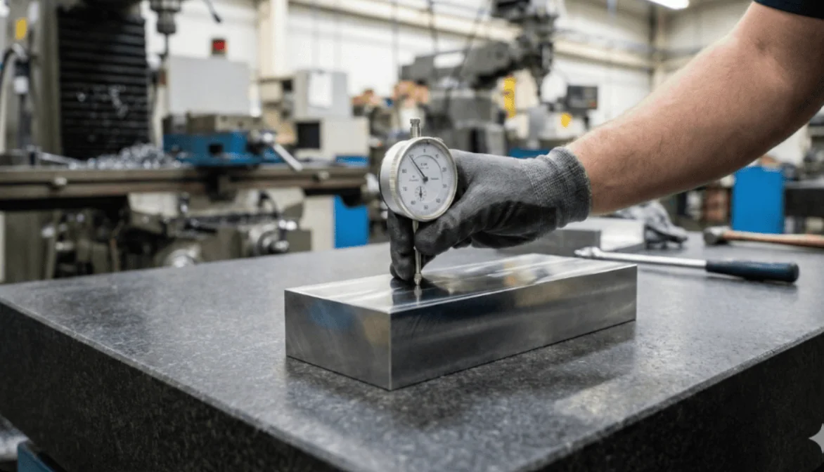
Verifying flatness requires specific metrology tools chosen based on the tolerance tightness, available inspection time, and the required accuracy. While there are various advanced techniques, the three most common methods in manufacturing are height indicators with dial gauges, Coordinate Measuring Machines (CMM), and optical laser interferometry.
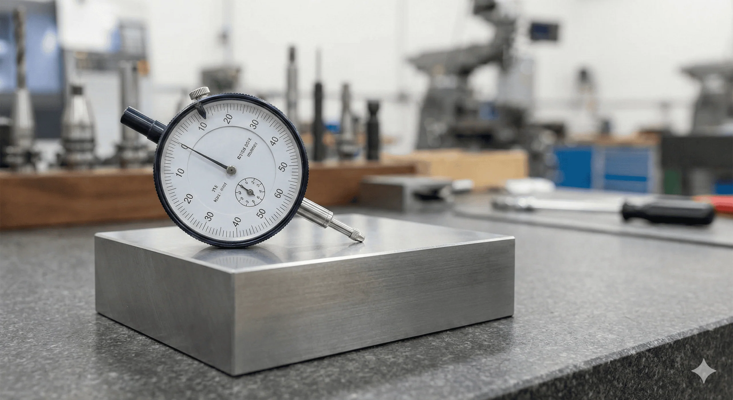
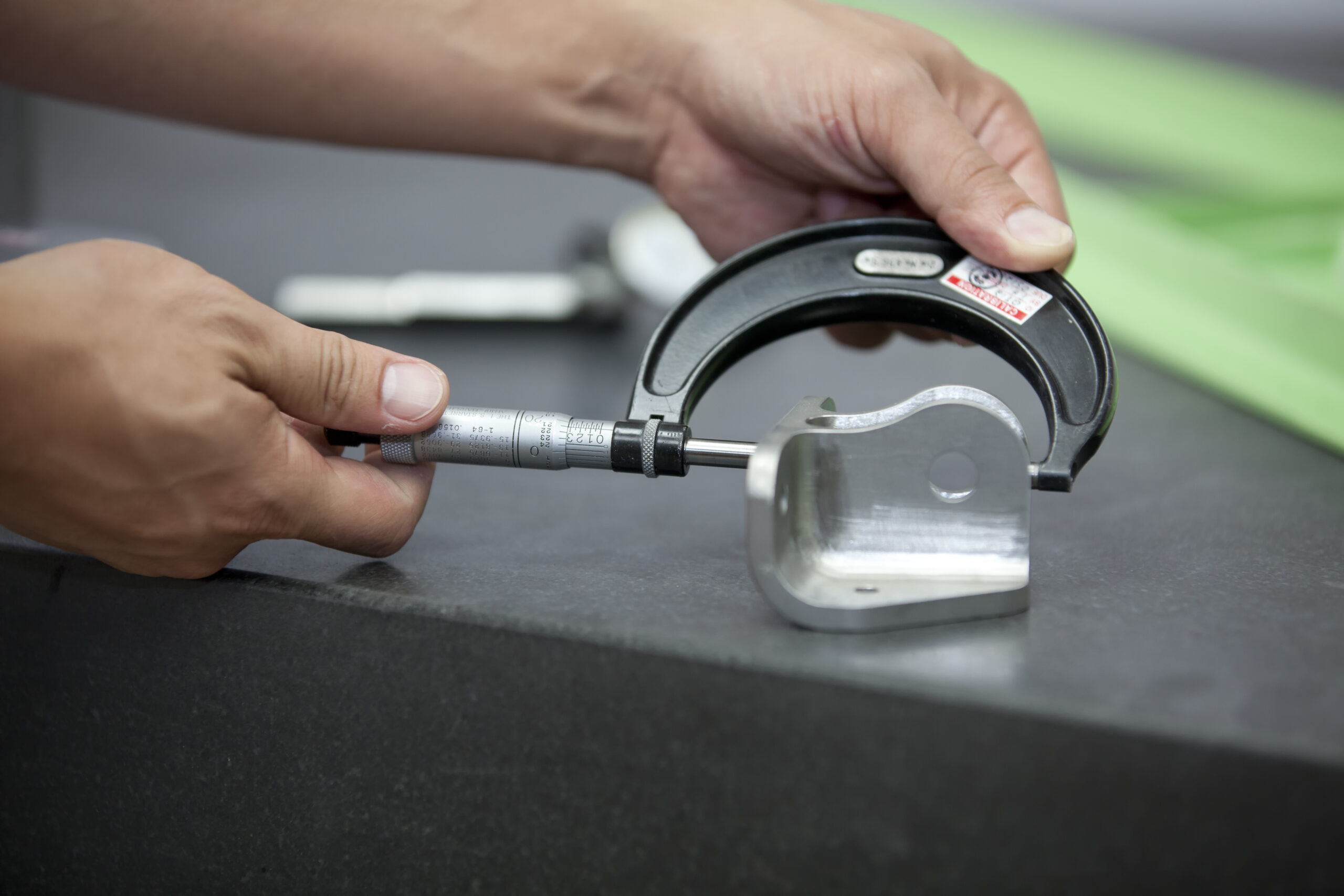
1. Height Gauge with Dial Indicator
Manual measurement with a dial gauge is the standard shop-floor approach. There are three distinct techniques to perform this, each with different levels of accuracy and setup requirements.
The Surface Plate Method (Quick Check): The most common daily procedure involves placing the part directly on a precision surface plate, zeroing the dial gauge on the surface, and sweeping it across the part. The difference between the maximum and minimum values represents the total deviation.
While this is a fast and convenient way to check a part, it technically measures parallelism, not just flatness. Since the part rests on the surface plate, the plate acts as the datum; any angle on the bottom surface of the part will influence the reading on the top. However, because flatness is an independent requirement, meaning the surface does not have to be parallel to the bottom, this method remains a practical « quick check » for many scenarios.
The 3-Point Jack Method (Recommended): For greater accuracy, we recommend isolating the controlled surface from the bottom face. This is achieved by propping the workpiece on three adjustable jacks with the controlled surface facing up.
The inspection process involves setting the dial gauge to zero at the points directly above the three jacks. By adjusting the height of the jacks individually, the operator brings the dial gauge to zero at all three reference points to create a virtual plane parallel to the surface. Once leveled, the operator sweeps the surface; the difference between the highest and lowest peaks constitutes the flatness deviation.

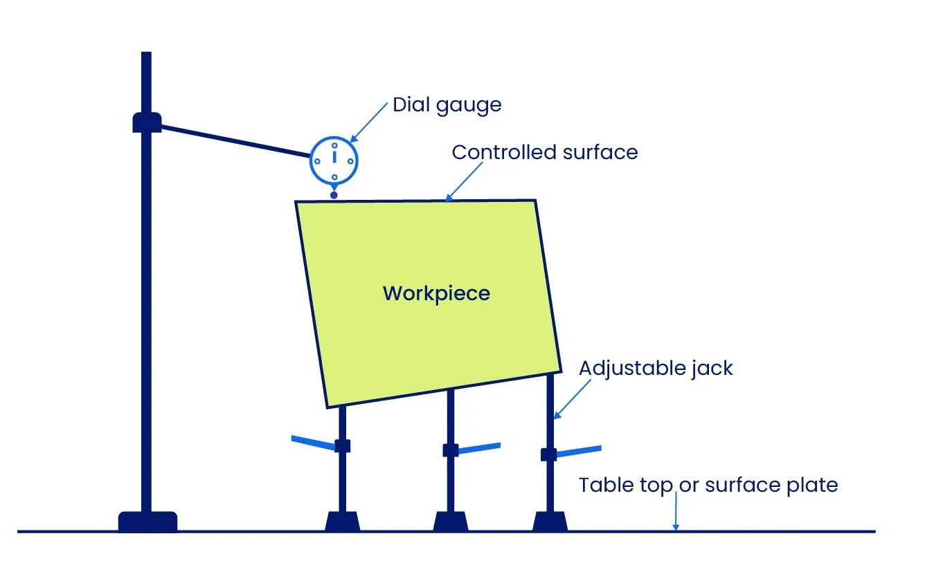
This method is more time-consuming but provides superior accuracy by establishing a true flatness tolerance zone independent of the table top.
The Face-Down Method: A third alternative involves placing the controlled surface face-down on a surface plate that has a hole in the center. The dial gauge probes the surface from underneath through the hole. While accurate, this method has a significant disadvantage: the operator must move the workpiece to scan the entire surface area. As the part moves, the specific high points contacting the plate change, which can introduce positional errors.
2. Using a Coordinate Measuring Machine (CMM)
For complex parts or automated inspection, a CMM is capable of generating highly precise flatness measurements. While software interfaces vary, the general process involves importing at least three orthogonal surfaces (using four points each) to define the coordinate system axes (X, Y, Z).
The CMM software uses these planes to calculate the envelope of the flatness tolerance zone, which consists of the two parallel planes within which all points must lie. The probe traces a defined grid of inspection points; a higher number of points with a thorough distribution yields a more accurate result.
A distinct advantage of the CMM is its ability to measure Features of Size. It can probe both sides of a part to generate the Derived Median Plane mathematically and then calculate the flatness of that imaginary center plane. This is impossible with manual dial gauges.
3. Using Optical Methods (Laser Interferometry)
For measuring extremely tight tolerances at the nanoscale level, laser interferometry is the standard. This is a non-contact method, making it ideal for large parts that cannot be measured with traditional tools or delicate parts that might deform under contact.
The system evaluates the interference patterns of two coherent light beams to calculate distance variations on the surface. While this provides the highest accuracy of all methods, it has limitations. It generally requires reflective surfaces and is highly sensitive to environmental noise, such as vibration and air turbulence.
Relation between Flatness Tolerance and Size Tolerance
Understanding the hierarchy between size and form is critical for creating valid engineering drawings. There are two distinct scenarios: standard applications (Surface Flatness) and applications involving Material Modifiers (Features of Size).
The General Rule: Flatness ≤ Size
According to the Envelope Principle (ASME Y14.5), the form of a feature must never violate its perfect boundary at Maximum Material Condition (MMC). Therefore, the flatness tolerance must always be less than or equal to the size tolerance.
Defining a flatness tolerance greater than the size tolerance creates a logical contradiction. For example, consider a plate with a thickness tolerance of 10 ± 0.2 mm (Total size tolerance = 0.4 mm). If we assign a flatness tolerance of 0.5 mm, it becomes impossible for the part to be within size limits (fitting within a 10.2 mm envelope) while simultaneously warping by 0.5 mm. Drawings with this error lead to conflicting inspection results and non-functional parts.
Flatness Tolerance at Different Material Conditions and Bonus Tolerance
The Exception: Bonus Tolerance with Material Modifiers
The only exception to the rule above is when Flatness is applied to a Feature of Size (Derived Median Plane) using a Material Modifier. In this scenario, the size tolerance controls the local dimensions, while the flatness tolerance controls the form independently.
Using Maximum Material Condition (M) or Least Material Condition (L) allows for Bonus Tolerance. This means the flatness tolerance can dynamically increase as the part’s actual size departs from the specified condition, granting manufacturers greater flexibility without compromising function.
1. Flatness with MMC and Bonus Tolerance The Maximum Material Condition (MMC) ensures that parts fit together even in the worst-case scenario. Consider a surface with a size tolerance of 100 ± 0.4 mm. Its MMC size (the largest permissible size) is 100.4 mm.
If we apply a flatness tolerance of 0.3 mm at MMC, this tolerance applies strictly when the part is at its maximum size. However, as the part is machined smaller (moving away from MMC towards LMC), the fit becomes looser. We can use this « extra room » to increase the flatness tolerance without affecting assembly.
The reduction in actual size from MMC is added to the flatness tolerance. This additional allowance is known as the Bonus Tolerance.
- Example Calculation: If the actual manufactured size is 100 mm (which is 0.4 mm smaller than the MMC of 100.4 mm), the manufacturer gains 0.4 mm of bonus tolerance.
Total Flatness Tolerance = Original Tolerance (0.3 mm) + Bonus (0.4 mm) = 0.7 mm.
At MMC (100.4 mm), the bonus is 0 mm. At LMC (99.6 mm), the bonus is maximized at 0.8 mm. This flexibility helps reduce manufacturing costs and wastage.
Calculation of Bonus Tolerance at MMC
(Specifications: Size = 100 ± 0.4 mm, Flatness = 0.3 mm at MMC)
| Part’s Actual Size (mm) | Bonus Tolerance (mm) | Total Flatness Tolerance (mm) |
| 100.4 (at MMC) | 0 | 0.3 |
| 100.3 | 0.1 | 0.4 |
| 100.2 | 0.2 | 0.5 |
| 100.1 | 0.3 | 0.6 |
| 100.0 | 0.4 | 0.7 |
| 99.9 | 0.5 | 0.8 |
| 99.8 | 0.6 | 0.9 |
| 99.7 | 0.7 | 1.0 |
| 99.6 (at LMC) | 0.8 | 1.1 |
Flatness with LMC and Bonus Tolerance
The Least Material Condition (LMC) is used for specific safety or functional requirements, such as maintaining a minimum wall thickness in a pressure vessel. While MMC ensures a snug fit, LMC ensures the part does not become too thin or weak.
When LMC is applied, the bonus tolerance calculation is inverted. The tolerance applies strictly at the LMC size (the smallest permissible size). As the part is machined larger (moving away from LMC towards MMC), the manufacturer gains bonus tolerance.
The amount of bonus tolerance is the difference between the LMC size and the actual size of the part. The bonus is zero when the part is at LMC and reaches its maximum when the part is at MMC.
Calculation of Bonus Tolerance at LMC
(Specifications: Size = 100 ± 0.4 mm, Flatness = 0.3 mm at LMC)
| Part’s Actual Size (mm) | Bonus Tolerance (mm) | Total Flatness Tolerance (mm) |
| 99.6 (at LMC) | 0 | 0.3 |
| 99.7 | 0.1 | 0.4 |
| 99.8 | 0.2 | 0.5 |
| 99.9 | 0.3 | 0.6 |
| 100.0 | 0.4 | 0.7 |
| 100.1 | 0.5 | 0.8 |
| 100.2 | 0.6 | 0.9 |
| 100.3 | 0.7 | 1.0 |
| 100.4 (at MMC) | 0.8 | 1.1 |
Glossary of Key Terms
| Term | Definition | Context |
| Total Flatness Zone | The default 3D tolerance zone consisting of two parallel planes. | Used for Surface Flatness. The entire surface area must lie between these planes. |
| Feature of Size | Any feature on a part that can be physically measured (e.g., a hole, pin, slot, or plate thickness). | Used when flatness controls the form of a specific dimension rather than just a surface. |
| Derived Median Plane | An imaginary plane calculated by connecting the center points of all opposing line elements on a feature. | Used when Flatness is applied to a Feature of Size (e.g., thickness of a plate). |
| Bonus Tolerance | Additional tolerance available when a feature of size departs from its Maximum Material Condition (MMC). | Only available for Flatness when applied to a Feature of Size with the (M) modifier. |
| Virtual Condition | The collective boundary generated by the combined effect of the feature’s size at MMC and the geometric tolerance. | Critical for designing mating parts to ensure proper assembly (e.g., a tab fitting into a slot). |
Mastering Form Controls
Flatness is one of the most versatile GD&T Form Controls, but it is rarely used in isolation. To create fully manufacturable parts, engineers must understand how it interacts with other tolerances:
- Vs. Straightness: If you only need to control a single line element on a surface rather than the entire face, use Straightness.
- Vs. Parallelism: If you need to control the orientation of the surface relative to a datum (e.g., keeping a table top parallel to the floor), use Parallelism.
- Vs. Surface Finish: If you need to control the microscopic roughness or texture of the surface rather than its macro-level form, use Surface Finish.
For deeper insights into these related controls, explore our comprehensive guide on Geometric Dimensioning and Tolerancing in the Xometry Pro technical library.


Comment(0)