 Europe
  Türkiye


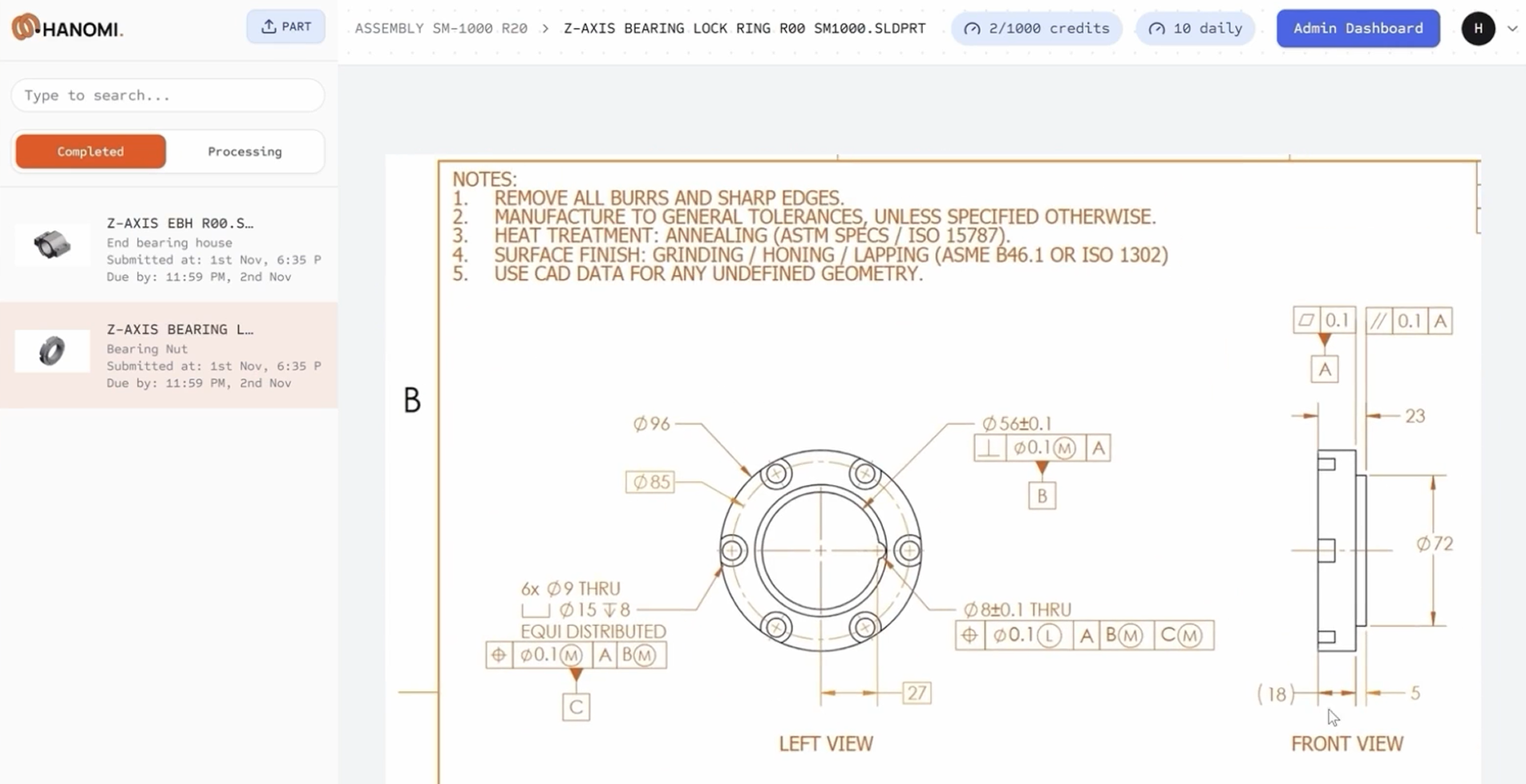
Whether detailing basic measurements or complex Geometric Dimensioning and Tolerancing, both methods convey the exact same manufacturing information, but they place the orthographic views in opposite positions on the drawing sheet.
Understanding the logic behind both methods is important to avoid confusion, especially when working with international partners.
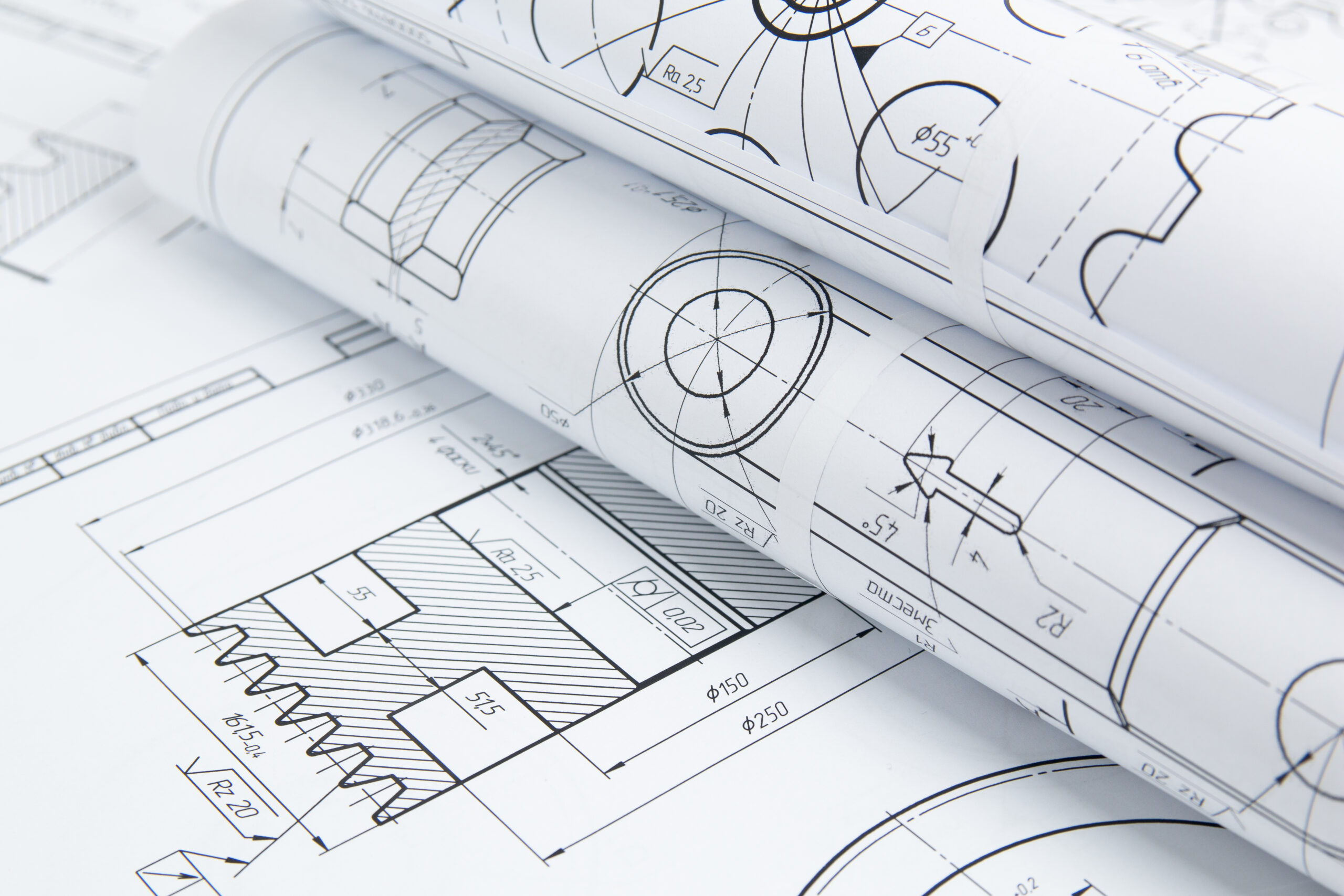
What Is Orthographic Projection?
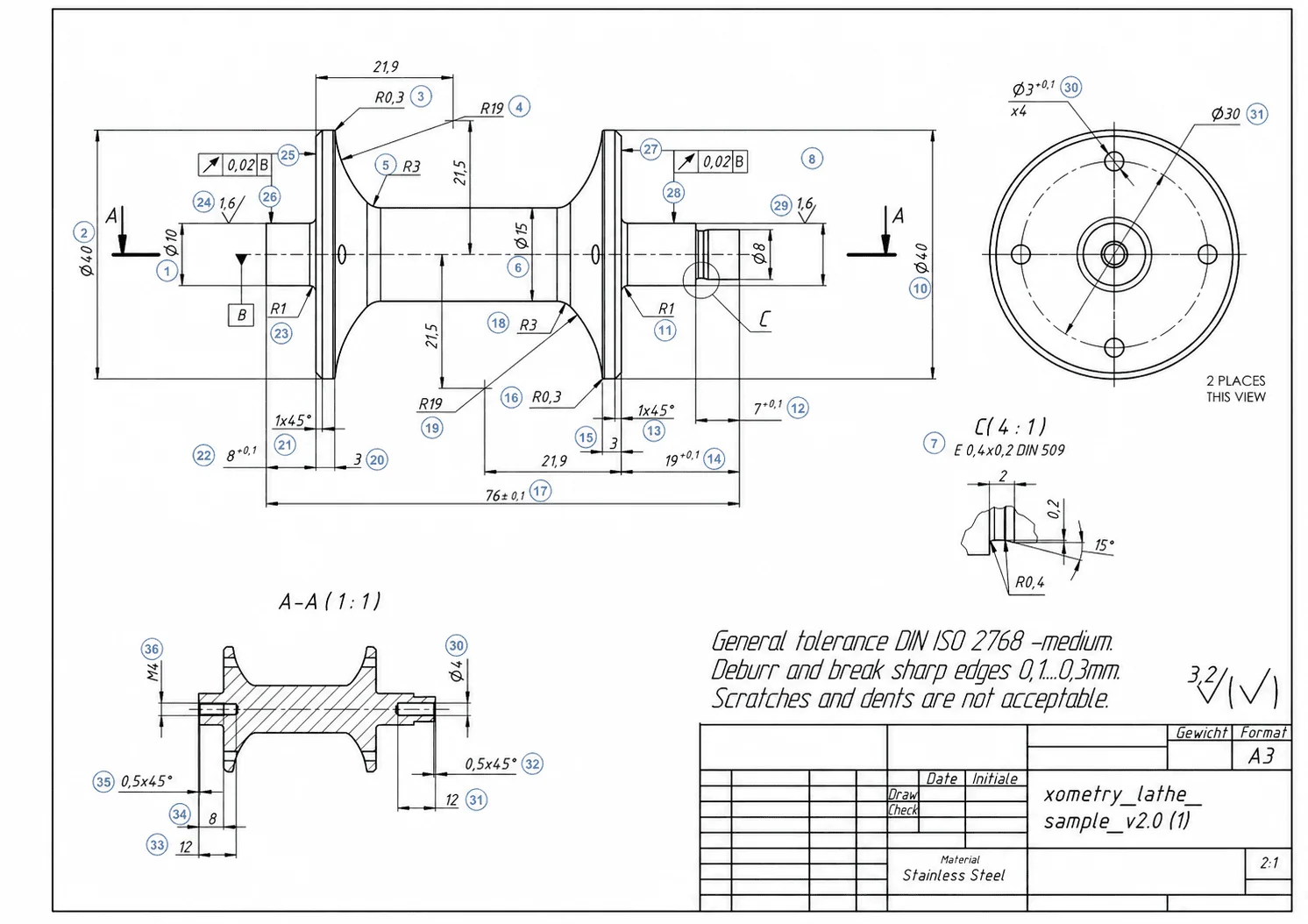
If you try to dimension a 3D isometric model directly on a 2D piece of paper, the perspective is distorted. Because only horizontal and vertical lines remain true to size, you cannot use the drawing’s denoted scale to measure angled lines. Therefore, adding standard manufacturing dimensions and tolerances to isometric views is impractical and inaccurate.
Instead, engineers project the necessary faces of a part onto flat planes. There are two primary projection planes: horizontal and vertical. These flat, 2D representations are known as orthographic projections (or dihedral projections in some regions).
A complete orthographic drawing can include up to six standard views. The vertical plane captures the front, back, and side views, while the horizontal plane captures the top and bottom views.
By placing the object between the observer and the projection plane, looking at it from different directions creates flat projections that show the true dimensions without perspective distortion.
First vs. Third Angle Projection: The Quadrants
| Feature | First Angle Projection | Third Angle Projection |
| Standard | ISO 128 | ASME Y14.3 |
| Common Regions | Europe, Asia, India | USA, Canada, Australia |
| Projection Logic | Object between observer and plane | Plane between observer and object |
| Top View Position | Below front view | Above front view |
| Left View Position | Right side | Left side |
| Right View Position | Left side | Right side |
| Intuitiveness | Less intuitive (initially) | More intuitive |
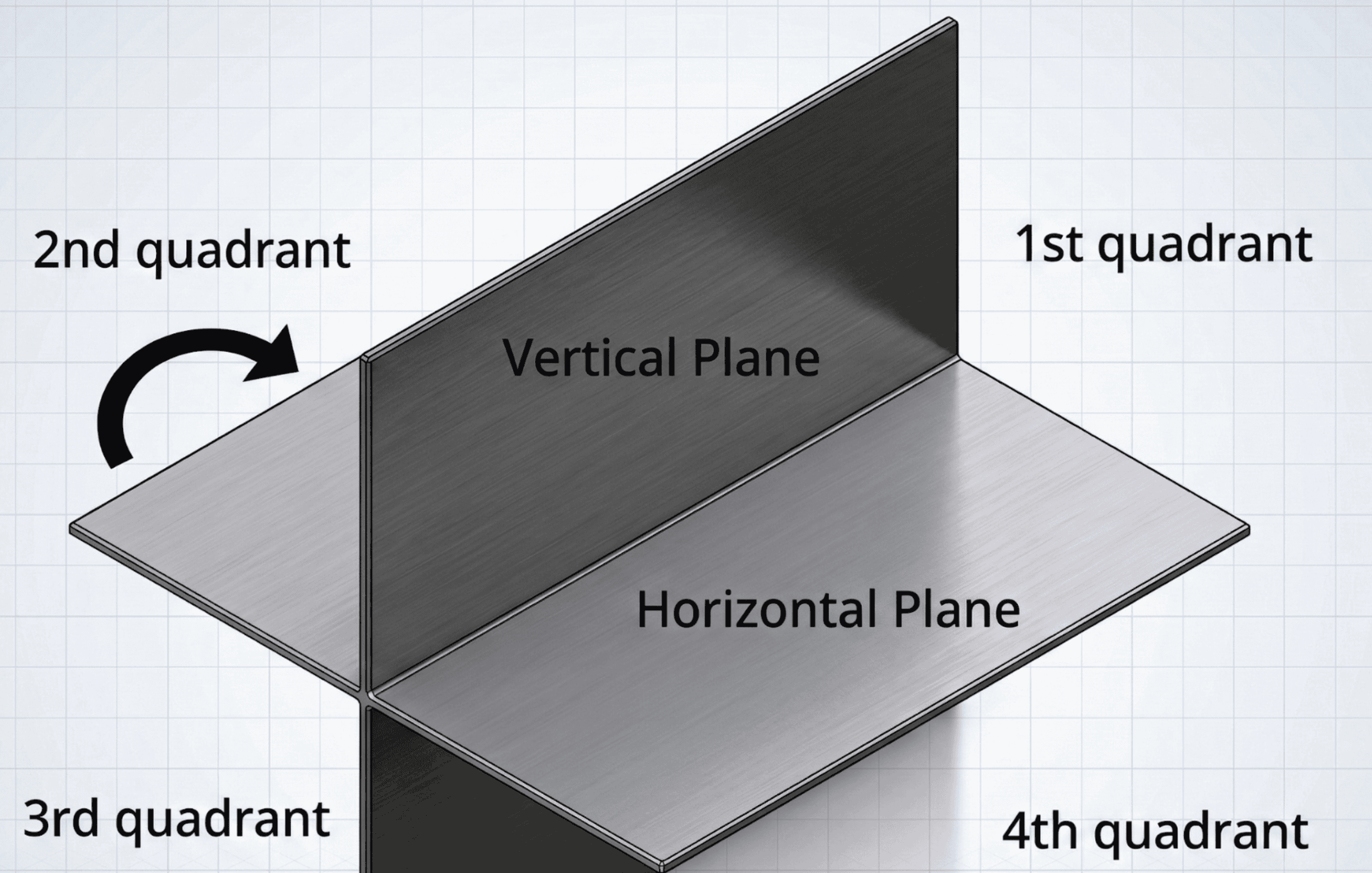
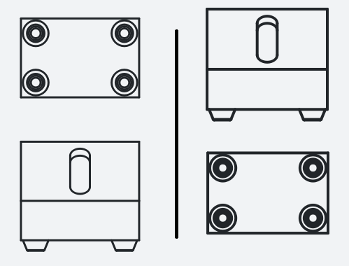
To understand how the views are arranged, imagine the vertical and horizontal projection planes intersecting to create four possible quadrants.
- First Angle Projection: The 3D model sits in the first quadrant.
- Third Angle Projection: The 3D model sits in the third quadrant.
For engineering drawing purposes, these two planes are conceptually “folded flat” so that all the views can be printed on a single 2D sheet of paper.
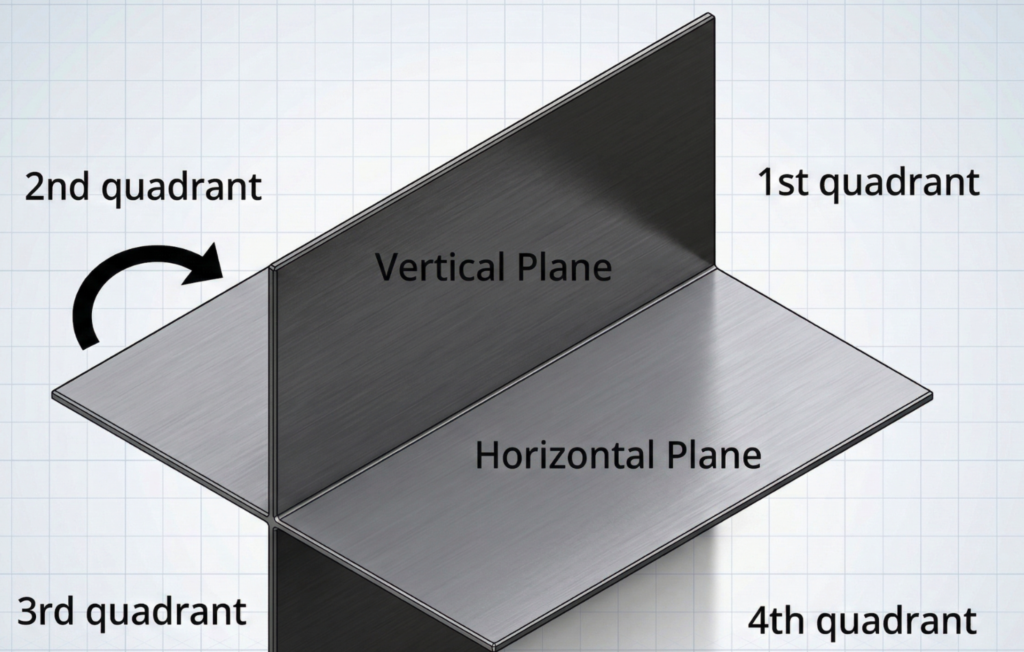
Why don’t we use the second and fourth angles?
In practice, they are useless. If you place an object in the second or fourth quadrant and fold the planes flat, the vertical and horizontal views project onto the exact same location, overlapping each other and making the drawing unreadable.
First Angle Projection (ISO Standard)
First angle projection is the dominant standard in Europe, India, and most of Asia, and is defined by the ISO 128-3 standard.
In first angle projection, the object is situated between the observer and the projection plane.
While some consider this method slightly less intuitive, the logic is simple: Imagine an object sitting on your desk. The side facing you is the Front View, which acts as the anchor for the drawing.
- If you flip the object downward, you see the top. Therefore, the Top View is placed below the Front View.
- If you flip the object to the right, you see the left side. Therefore, the Left Side View is placed on the right of the Front View.
The Rule of First Angle: Views are projected onto the opposite side of where you are looking.
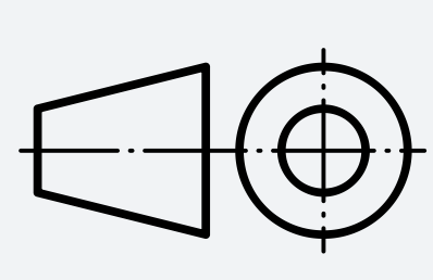
The Symbol: Every engineering drawing indicates its projection method in the title block. The first angle projection symbol shows the side and top views of a truncated cone, with the cone’s wider base facing toward the top view.
Third Angle Projection (ASME Standard)
Third angle projection (often called the American projection system) is the standard used in the United States, Canada, Japan, and Australia. It is defined by the ASME Y14.3 standard.
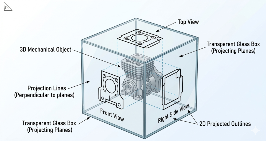
In third angle projection, the projection plane sits between the observer and the object (imagine looking through a transparent glass box at the part inside).
Because the projection plane is in front of the object, the views are located on the exact same side as the direction you are looking from.
- Look at the top of the object, and you draw the Top View above the Front View.
- Look at the right side of the object, and you draw the Right Side View on the right.
The Rule of Third Angle: Views are projected onto the same side from which you are looking. Most modern engineers consider this layout to be highly intuitive.
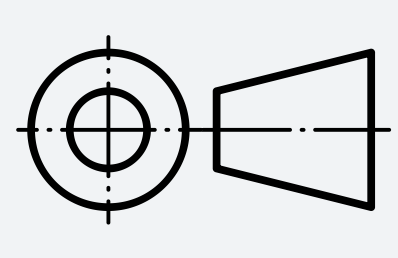
The Symbol: The third angle projection symbol shows two concentric circles with the smaller diameter of the side view facing away from the top view.
Comparing the Standard Views
Let’s walk through the main orthographic views to see the practical differences side by side.
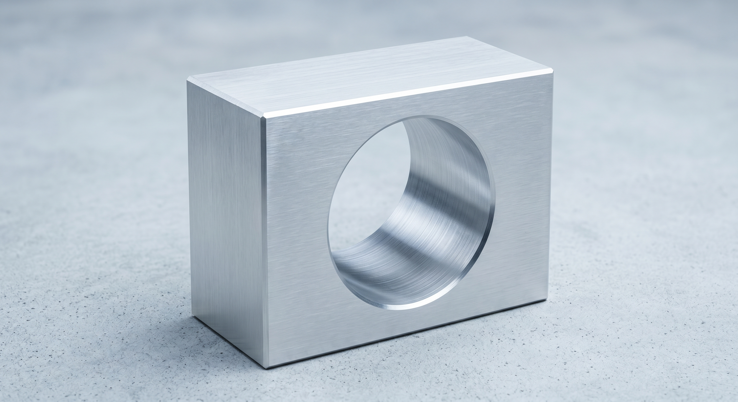
Front View

The front view is the starting point for any orthographic drawing. It should be chosen to showcase the most characteristic or functional features of the part, usually capturing the general length and height. Because it serves as the base for all other projections, the front view is positioned the exact same way in both first and third angle projection.
Side View
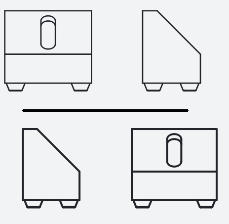
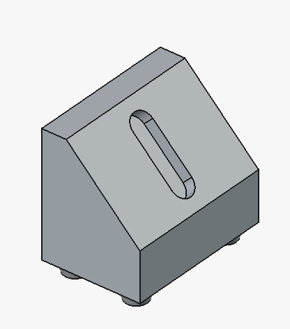
The side view adds information about depth, something the front view cannot convey. In this example, the left side view reveals the position of the legs, the depth of the part, the angle and size of the chamfer. Either a section view or hidden lines would be needed to dimension the depth of the slot.
Top view
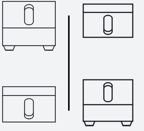
The top view shows features visible from above. In this example, the top face has no features. So it would be sensible to exclude the view from the main drawing to minimize clutter.
Bottom view
The bottom view reveals under-side features. For example, if a part has cylindrical feet, the front view might just show rectangular blocks, but the bottom view will reveal their true circular profile.
Auxiliary views
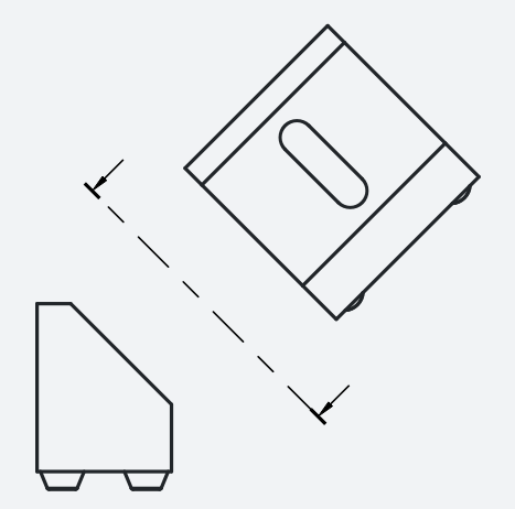
Sometimes, the standard orthographic views still cannot depict a complex angled feature without distortion. So the current model would need an extra auxiliary view to show the true proportions of the slot. Because they are independent of the standard quadrant layout, auxiliary views are placed the same way in both projection systems.
Isometric view
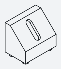
An isometric view is an optional 2D projection where the three spatial axes are separated by 120 degrees. It gives the machinist a quick, visual 3D overview of the part. Isometric views are never dimensioned.
Best Practices for First Angle vs. Third Angle
| Scenario | Actionable Best Practices |
| Before Using a Drawing | Locate the projection symbol in the title block.
Verify the standard in use (ISO vs. ASME). Confirm with the supplier or client if anything is unclear. |
| When Creating Drawings | Choose the projection method based on the target region and manufacturing partner.
Keep the layout and projection style completely consistent across the drawing pack. |
| When Working Globally | Do not assume your international partners share your local standards.
Clearly state the projection method in the title block, supporting documentation, and communications. |
| When Using CAD Software | Familiarize yourself with how your specific CAD tool switches between first angle and third angle.
Always export final drawings with the correct projection setting applied and the symbol clearly visible. |
The Choice
The choice between first angle and third angle projection comes down entirely to regional conventions. Europe and Asia predominantly use first angle, while North America and Australia rely on third angle. Neither system has an inherent technical advantage over the other.
As an engineer or designer, what matters most is consistency. Always explicitly mark your projection method in the technical drawing’s title block and stick to that system throughout the entire drawing pack. If you are supplying drawings to an overseas client or a global manufacturing partner like Xometry, always confirm which system their machinists expect to receive.

Comment(0)