

 Europe
  Türkiye
  United Kingdom
  Global









 Login with my Xometry account




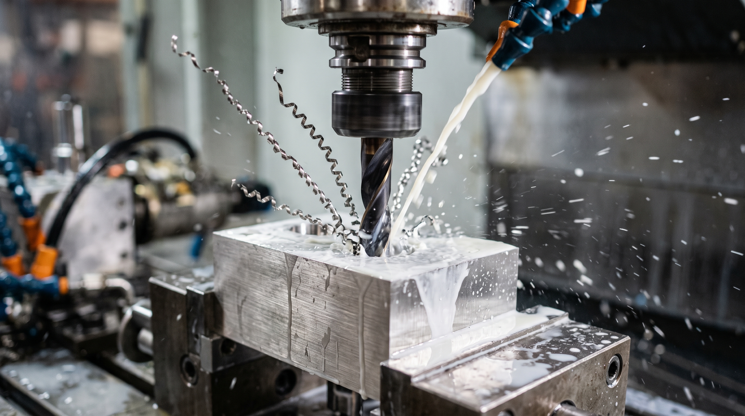
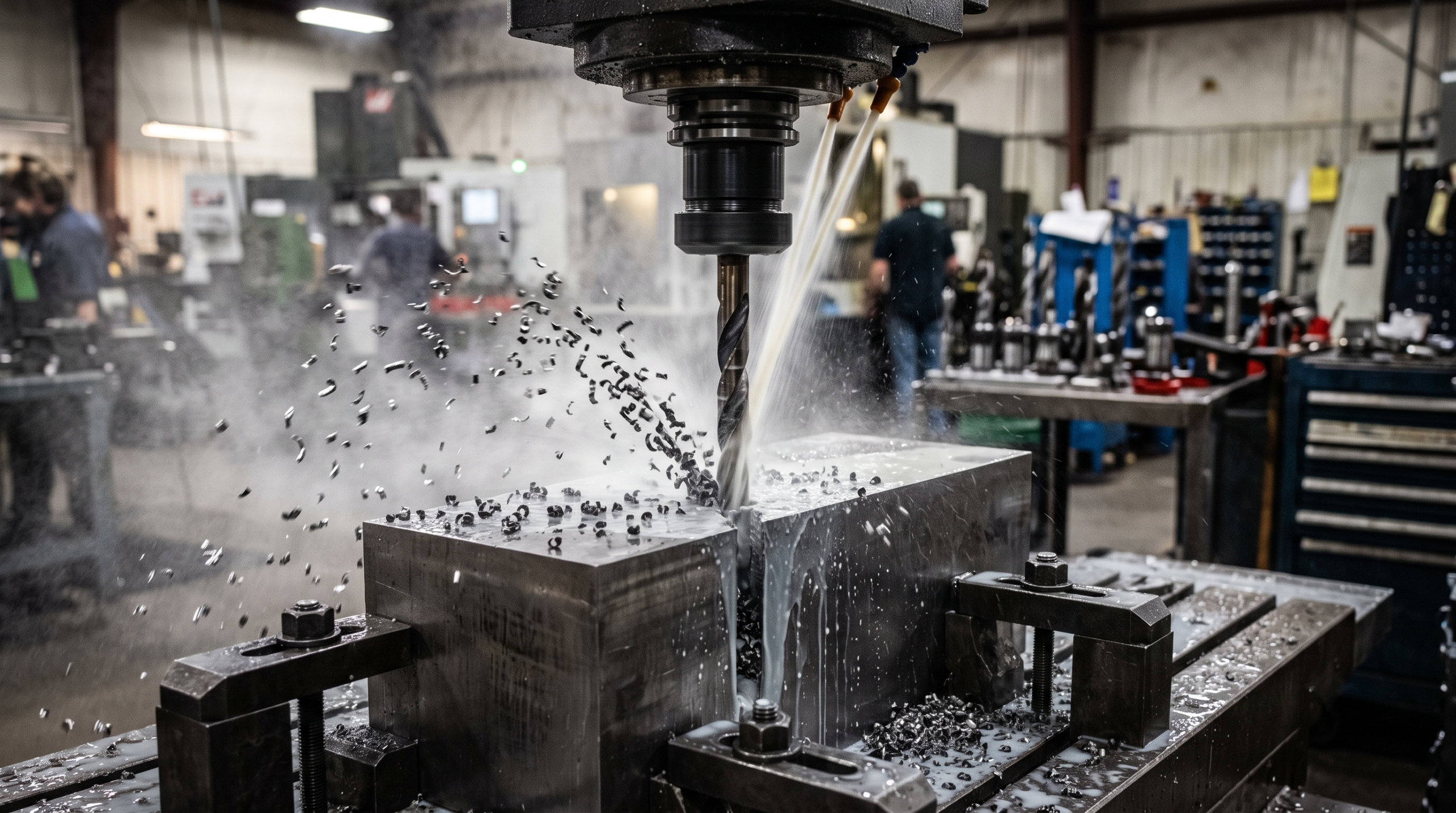
The fix is not a better drill. It is understanding how cutting speed and feed rate work together, and why optimizing one without the other invites exactly this kind of failure.
What Cutting Speed and Feed Rate Are?
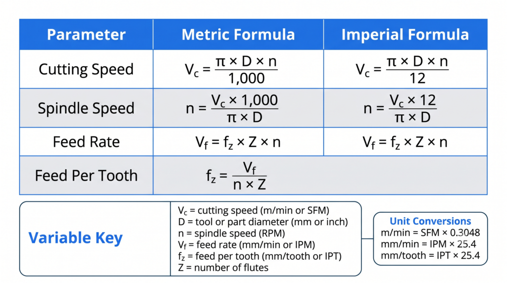
Cutting speed is the relative velocity between the cutting edge and the workpiece surface at the point of cut, measured in meters per minute (m/min) or surface feet per minute (SFM). In turning, it is the peripheral speed of the rotating workpiece. In milling, it is the peripheral speed of the tool, driven by spindle RPM and cutter radius.
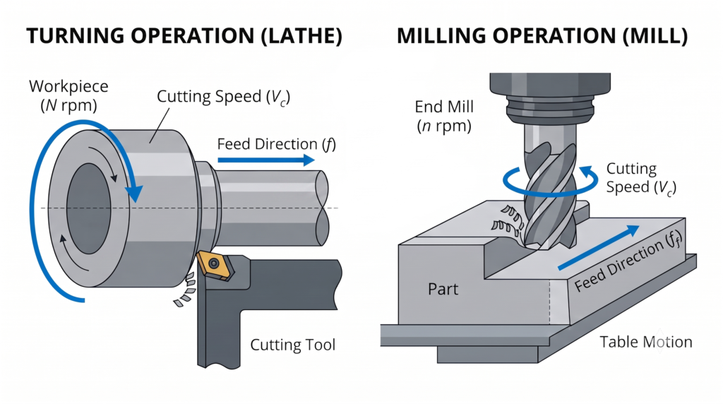
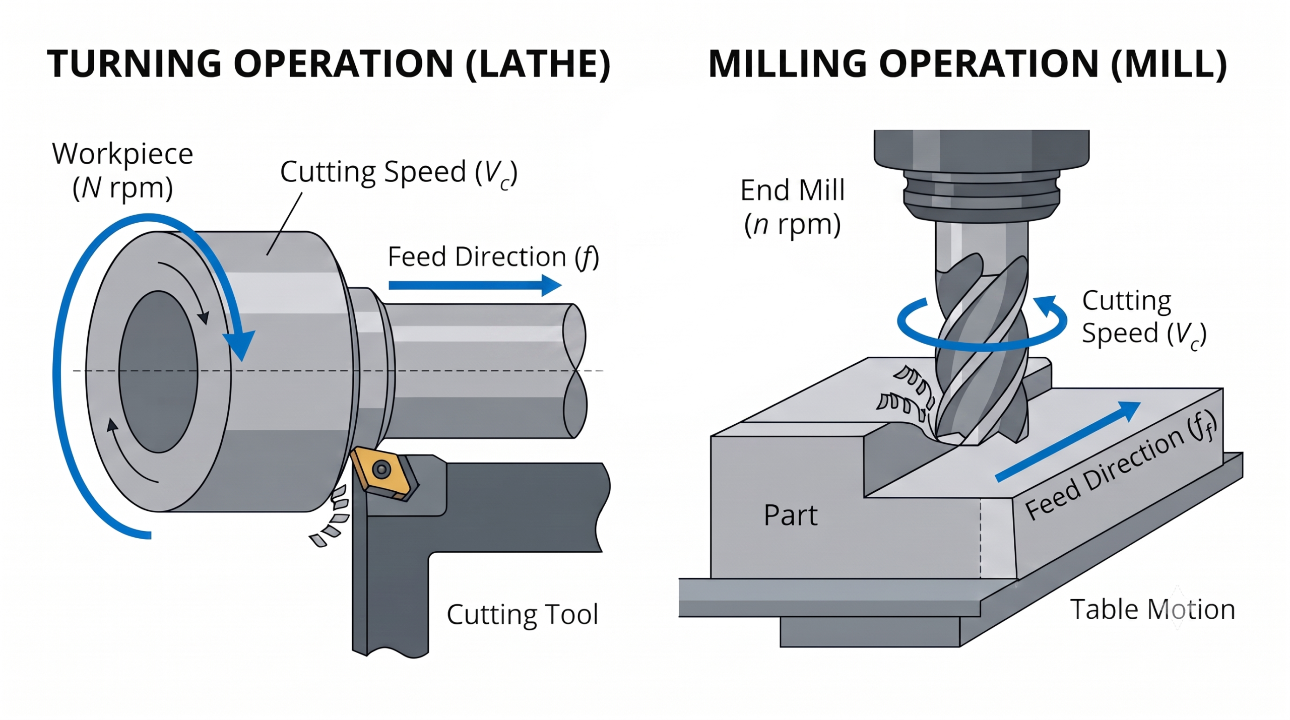
Feed rate is the distance the tool advances relative to the workpiece per unit of time, measured in millimeters per minute (mm/min) or inches per minute (IPM). It also appears as feed per revolution (mm/rev) in turning and drilling, or feed per tooth (mm/tooth, also called chip load) in milling.
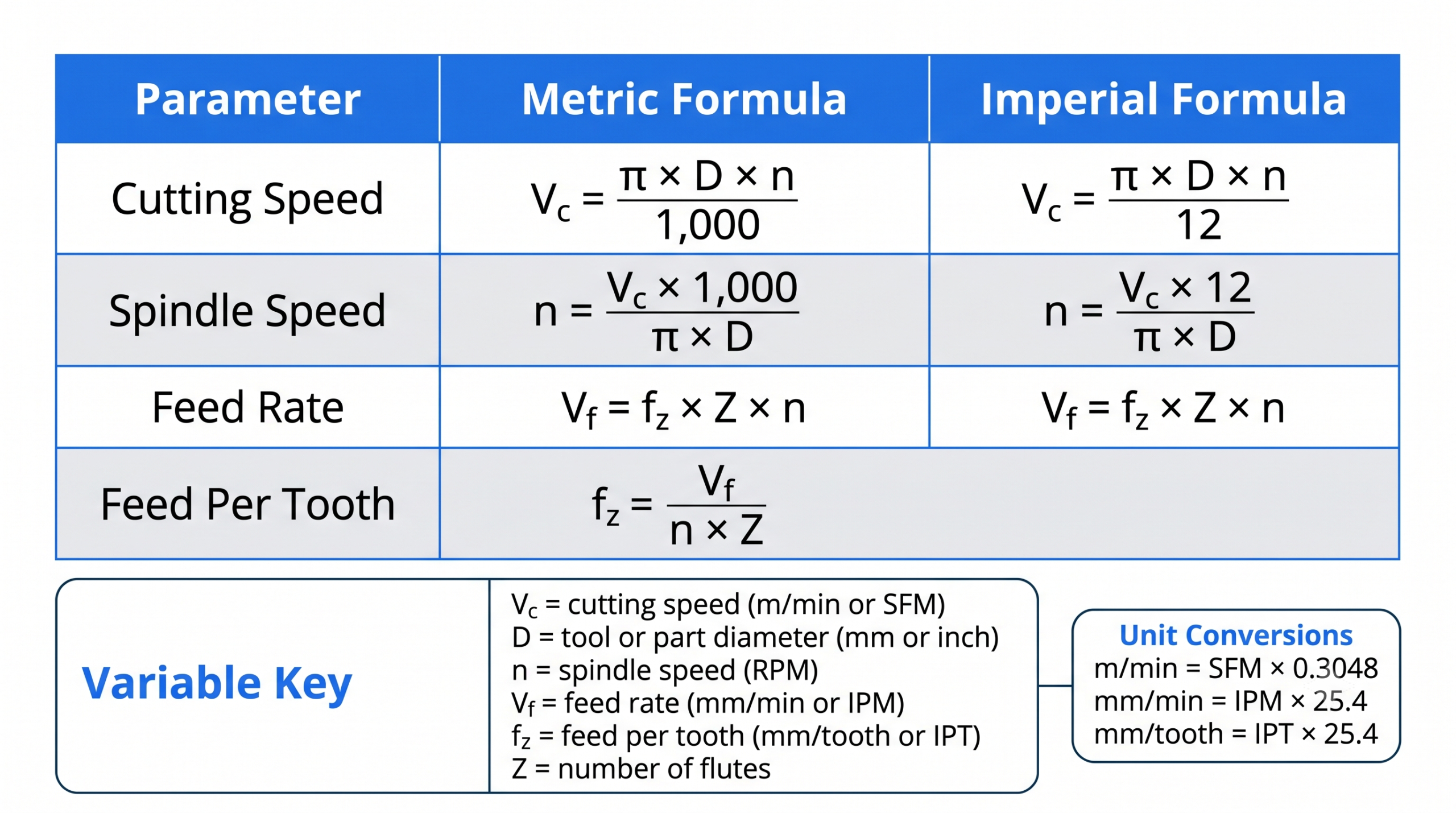
Effects of Cutting Speed and Feed Rate
Varying cutting speed and feed rate changes surface roughness, tool life, cutting temperature, material removal rate, power consumption, chip formation, vibration, dimensional accuracy and cutting force. Finding the optimal values means balancing productivity, machining cost and part quality.
Lower feed rates improve surface finish and hold tighter tolerances by reducing feed marks and cutting force. Lower cutting speeds reduce heat generation and extend tool life, though speeds set too far below the recommended range can cause built-up edge (BUE) formation, where workpiece material sticks to the cutting edge and deteriorates the surface.
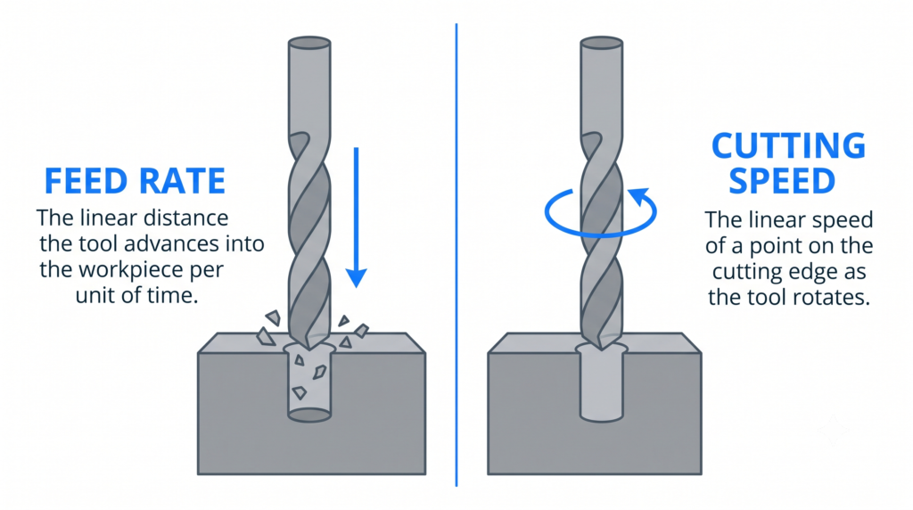
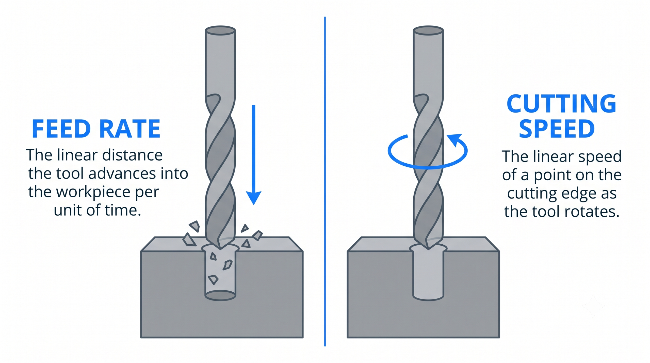
Lowering cutting speed and feed rate reduces vibration and tool wear at the cost of production efficiency. Increasing them boosts material removal rates but risks thermal damage, excessive forces, and surface roughness. Machinists typically increase speed within recommended ranges until reaching the threshold of tool wear or quality limits.
Cutting Speed vs Feed Rate Comparison
| Feature | Cutting speed | Feed rate |
| What it is | Relative velocity between tool and workpiece | Rate at which the tool advances along the workpiece |
| Primary deciding factor | Hardness of workpiece and tool material | Tool strength, desired surface finish and machine rigidity |
| Effect on productivity | Faster cycle times | Higher material removal rate |
| Primarily influences | Tool life and heat generation | Material removal rate and surface finish |
| Effect on surface finish | Higher speeds reduce BUE and improve finish | Lower feed rates reduce feed marks and improve finish |
| How it’s measured | m/min or SFM | mm/min, IPM, or feed per tooth/revolution |
| Excessively high values cause | Tool wear and thermal damage | High cutting force and tool breakage |
| Excessively low values cause | Poor efficiency, workpiece hardening from rubbing | Tool dulling, BUE formation, work hardening |
Parameter Extremes and Their Signatures
| Symptom on the part or tool | Likely cause | Corrective adjustment |
| Shiny, burnished flank wear | Cutting speed too low, tool rubbing | Increase cutting speed toward recommended range |
| Blue or discolored chips | Cutting speed too high, excess heat | Reduce cutting speed or increase coolant flow |
| Deep, visible feed marks | Feed rate too high for finish target | Reduce feed rate on finishing pass |
| Snapped tool at entry | Feed rate too high for chip evacuation | Reduce feed rate, verify pecking cycle on drilling |
| Built-up edge on cutting face | Speed or feed too low for material | Increase both toward manufacturer range |
Factors Affecting Cutting Speed
Four primary factors affect cutting speed: cutting tool material, workpiece hardness, expected tool life and depth of cut.
Cutting tool material
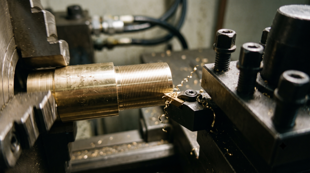
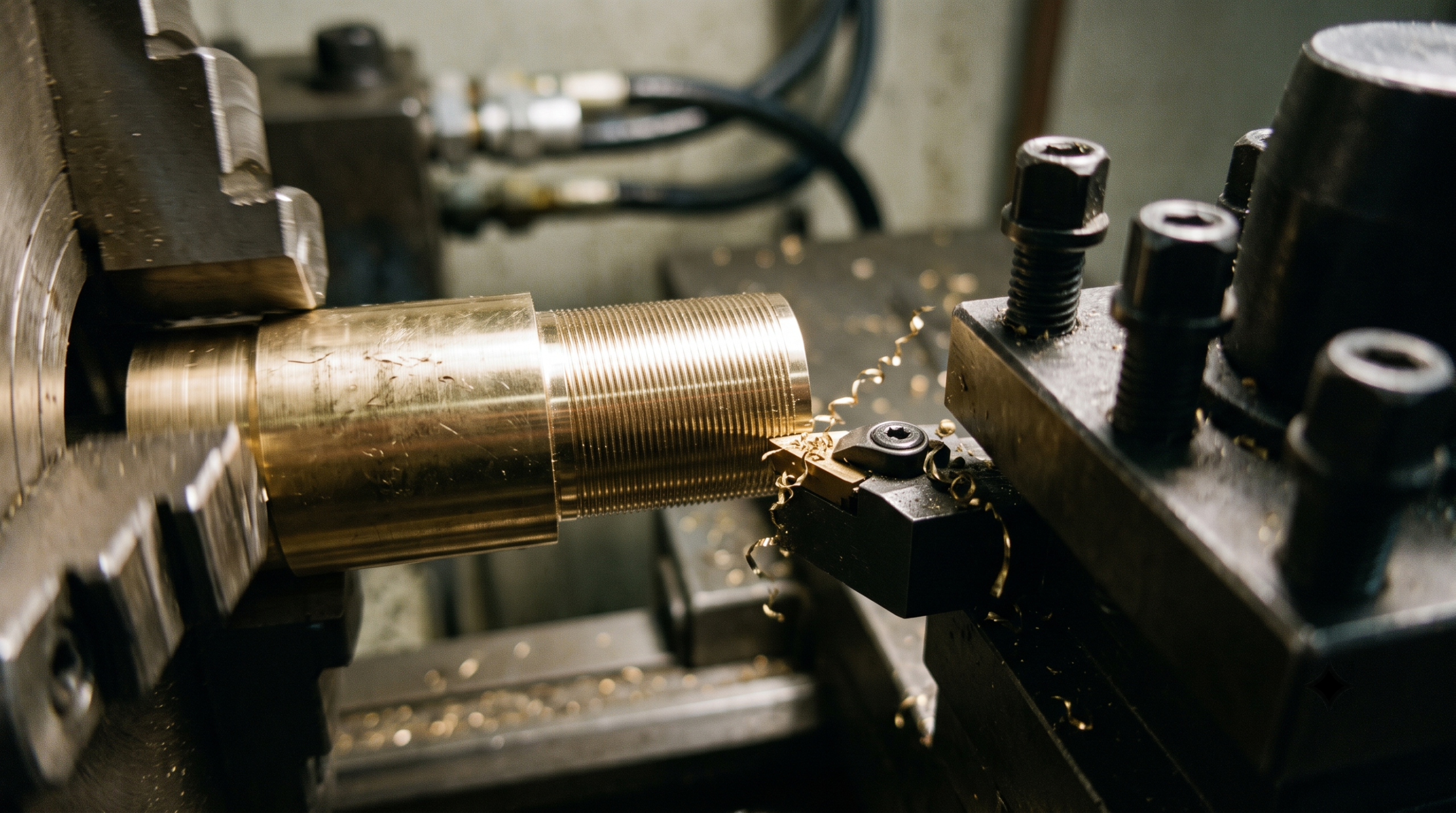
The cutting tool’s material strongly influences the allowable cutting speed, since different materials have different hardness, hot hardness, wear resistance and thermal stability. A material that holds its hardness at elevated temperatures can cut at higher speeds without rapid wear or failure.
| Tool material | Effect on cutting speed | Application |
| High-speed steel (HSS) | Limited to low speeds due to lower hot hardness (up to 30 m/min) | Low-volume, manual machining, drilling, tapping |
| Carbide | Higher hot hardness and wear resistance permit higher speeds (60 to 300 m/min) | General-purpose milling, turning and drilling |
| Polycrystalline diamond (PCD) | Superior hardness and wear resistance, extremely high speeds (200 to 1,200 m/min) | Non-ferrous materials: aluminum, graphite, composites |
| Cubic boron nitride (CBN) | Exceptional hot hardness and thermal stability (100 to 400 m/min) | Hardened ferrous materials and hardened alloys |
| Ceramic | High-temperature resistance up to 1,200 °C enables very high speeds (300 to 1,200 m/min) | High-speed finishing of superalloys |
Workpiece hardness
When the same tool material cuts workpieces of different hardness, cutting speed must be adjusted to prevent tool failure. Harder workpieces require slower speeds, and speed increases for softer materials. Mild steel machines comfortably at high cutting speeds, while hardened steel forces a sharp drop in speed, especially with conventional carbide tools.
Switching to a more wear-resistant tool, such as ceramic or CBN, recovers some of that lost speed and restores productivity. The right speed comes from comparing the effect on tool life, productivity, surface finish and economic feasibility.
Expected tool life
Cutting speed and tool life have an inverse relationship, expressed in Taylor’s tool life equation:
V × Tⁿ = C
| Symbol | Variable | Description |
| V | Cutting speed | Selected operating speed |
| T | Tool life | Time to tool failure at speed V |
| n | Tool life exponent | Depends on the tool-workpiece pairing |
| C | Constant | Fixed for a given tool-workpiece combination |
Even moderate increases in cutting speed significantly reduce tool life due to excess heat and wear. For instance, in one carbide tool/alloy steel pairing, raising the speed from 100 to 130 m/min (a 30% increase) slashed tool life from 150 minutes to just 52 minutes.
Machinists must balance these tradeoffs: lower speeds prioritize longer tool life for roughing or expensive tooling, while higher speeds boost productivity in mass production, provided the tool life remains economically viable.
Depth of cut
Depth of cut scales roughly linearly with cutting load. A larger depth of cut generates more heat and faster tool wear, so it typically pairs with a lower cutting speed. The tradeoff still favors productivity, since fewer passes are needed to reach final dimensions.
Depth of cut and feed rate together determine total cutting load, so a large depth of cut combined with a high feed rate requires a significant cutting speed reduction to avoid overheating and tool failure.
Factors Affecting Feed Rate
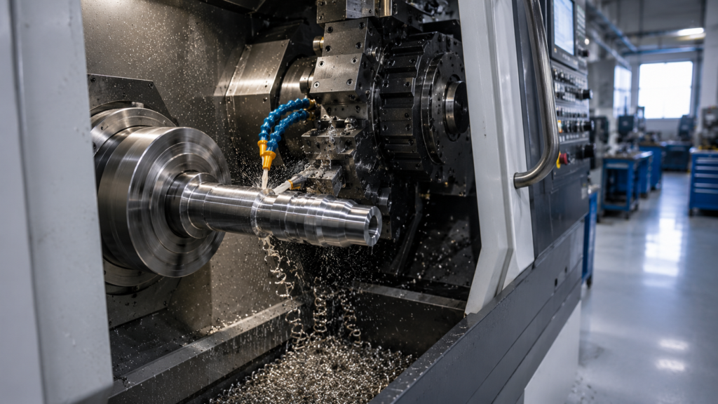
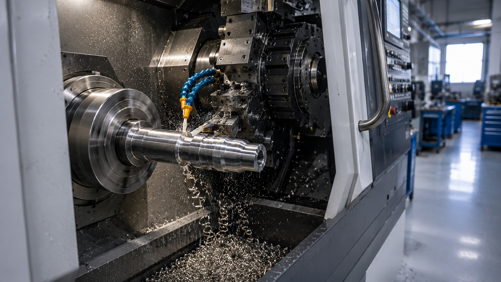
The feed rate is also highly variable, influenced by a variety of factors. Many of these factors are considered by tool manufacturers when defining the recommended feed rates for their tools. Some of these are:
- Tool and workpiece material
- Tool geometry
- Surface finish requirement
- Cut width
Tool and workpiece material
Harder workpieces generate higher cutting forces and require lower feed rates to protect the tool. Hardened steel runs at low feed rates, aluminum tolerates high feed rates because it is soft, and ductile materials sit in a moderate range to avoid built-up edge.
Tool geometry
Rake angle, nose radius, edge strength, flute design, helix angle, and relief angle all affect cutting forces and chip evacuation, and therefore the feed rate a given tool can sustain.
Surface finish requirement
A smoother target finish requires a lower feed rate. Higher feed rates increase surface roughness and leave deeper feed marks.
Cut width
Cut width, also called radial depth of cut or stepover in milling, defines how much of the tool engages the workpiece. Greater radial engagement raises cutting force, heat, and spindle load, so a higher cut width pairs with a lower feed rate to hold machine stability.
How Cutting Speed and Feed Rate Interact
Cutting speed and feed rate rely on similar factors and cannot be optimized independently, since together they set cutting force, heat generation, machine stability, chip formation and tool wear. Even when each parameter looks acceptable on its own, an aggressive combination can overload the tool or machine.
Speed and Feed Combinations
| Combination | Best suited for | Trade-off |
| High speed, high feed | Mass production, fast cycle times | High force and heat, needs hard tooling, lubrication and rigid workholding |
| High speed, low feed | Finishing passes, smooth surface, tight accuracy | Low feed risks tool rubbing and edge dulling |
| Low speed, high feed | Roughing tough materials, limited heat generation | Poor surface finish, higher cutting force |
| Low speed, low feed | Wear-resistant or delicate materials, chatter-prone setups | Low material removal rate, longer cycle time |
Optimizing Machining Rates
Maximizing speed and feed reduces cycle times but risks increased tool wear, heat, and costs. Machinists balance these trade-offs using these methods:
Optimization Methods
| Method | What it provides | Best used for |
| Manufacturer cutting data | Baseline ranges for speed, feed, chip load, depth of cut and coolant by tool and material | Initial parameter setup before any cut |
| CAM software recommendations | Suggested feed, speed, toolpath and depth of cut based on material and geometry, plus collision and cycle-time simulation | Programming complex parts and multi-tool jobs |
| Trial cuts | Validation of manufacturer and CAM data against real workholding, rigidity and coolant conditions | Confirming chip load, vibration and finish before production |
| Tool wear monitoring | Direct feedback on flank wear, crater wear, chipping and thermal cracking | Ongoing refinement during production runs |
Manufacturer cutting data comes from standardized charts based on tool material, geometry, workpiece material, coating and operation.
CAM software such as Mastercam, Fusion 360 and Esprit builds on this with simulation of tool engagement and cycle time.
Trial cuts catch what simulation misses, such as unstable workholding or inadequate rigidity, and any deviation is corrected by adjusting speed or feed.
Tool wear monitoring, including spindle load, vibration and acoustic sensors, shows directly whether current parameters are too aggressive.


DfM Guidance for Speed and Feed Parameters
Design decisions constrain the speed and feed window a machinist has to work with, and a few choices at the drawing stage keep that window as wide as possible.
| Design Factor | Process Constraint | Recommendation |
| Deep or small-diameter holes | Chip evacuation limits feed rate | Specify pilot holes or peck cycles rather than forcing a single deep pass |
| Tight surface finish callouts | Forces lower feed rate and longer cycle time | Reserve fine finish specs for functionally necessary surfaces only |
| Thin walls or unsupported features | Limits achievable depth of cut and cutting force | Add support ribs or increase wall thickness where function allows |
| Hard-to-machine materials (stainless, titanium) | Reduces safe cutting speed range | Flag material choice early so tooling and cycle time are budgeted correctly |
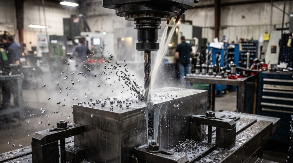
Engineers sizing hole diameters for tapped features can cross-check drill sizing against thread requirements with the thread and thread and tap drill size calculator before finalizing feed rate assumptions for drilling operations.
Dialing In Speed and Feed
Cutting speed and feed rate are not independent dials. Speed governs heat and tool wear, feed governs cutting force and surface finish, and both draw from the same mechanical budget. The combination that maximizes throughput is rarely the combination that protects the tool, so the right answer depends on manufacturer data, CAM simulation, trial cuts, and wear monitoring working together rather than any single number in isolation.
Related Topics
 2
2
2
2



Comment(0)