 Europe
  Türkiye


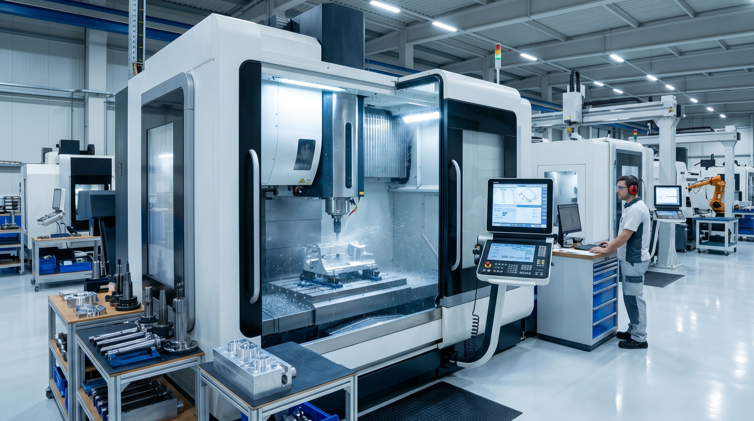
The high degree of control achieved through automation is what sets CNC apart from other manufacturing technologies. This automation makes it highly price-competitive for both one-off custom prototypes and low-to-medium volume production runs.
What is CNC Machining?
CNC machining is a subtractive manufacturing process where computer-controlled machine tools remove material from a solid block, also known as a blank or workpiece, to produce a finished part.
The cutting paths, speeds and tool changes are all driven by a program, enabling high repeatability. Modern CNC systems can run largely unattended, with the operator’s role limited to setup, programming and quality checks.

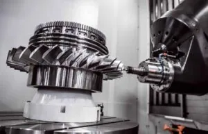
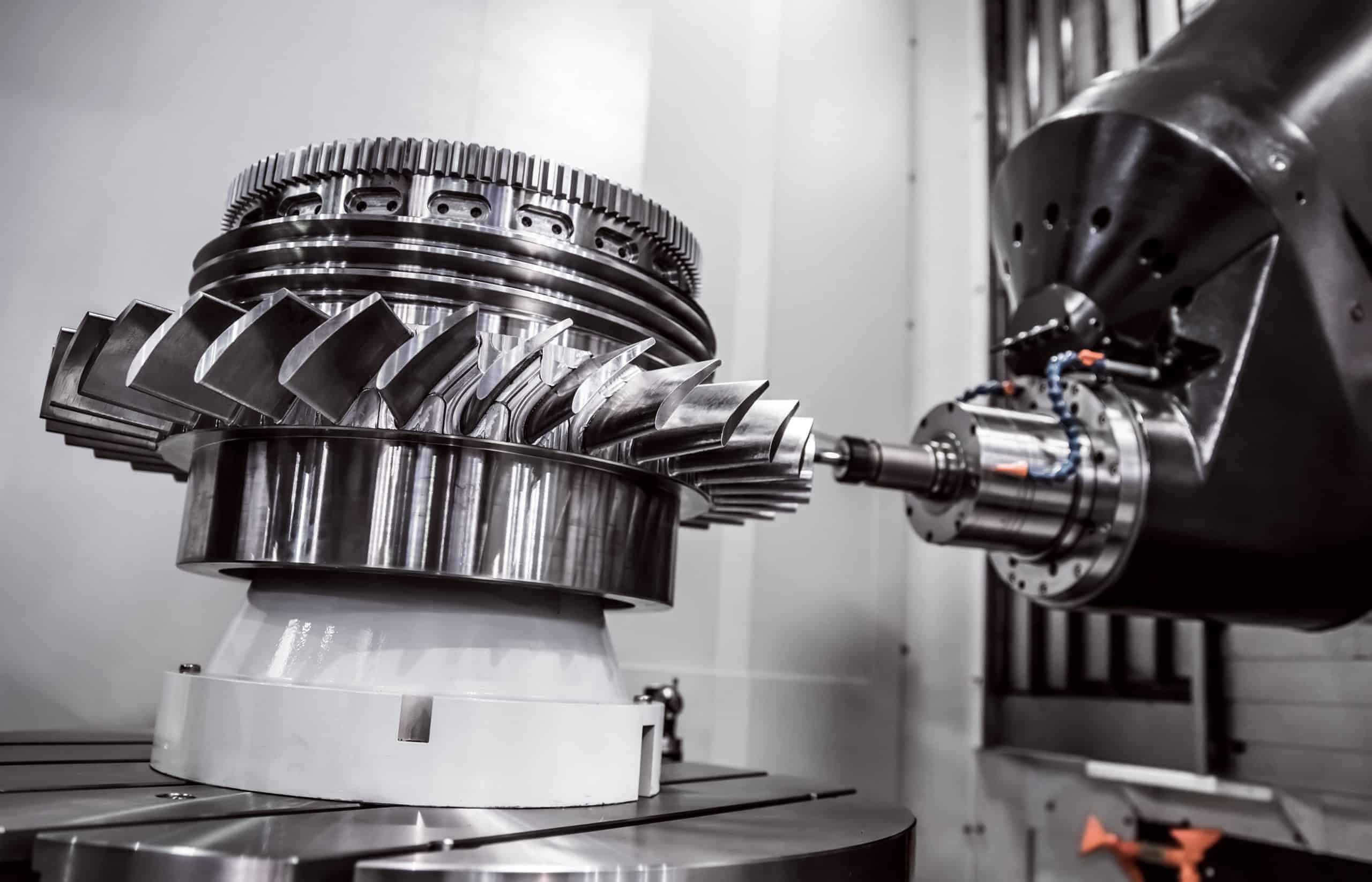
Multi-axis machines can produce complex geometries like turbine rotors, pump impellers, and free-form surfaces in a single setup that would have required multiple machines and manual repositioning in the past.
What is CNC (Computer Numerical Control)?
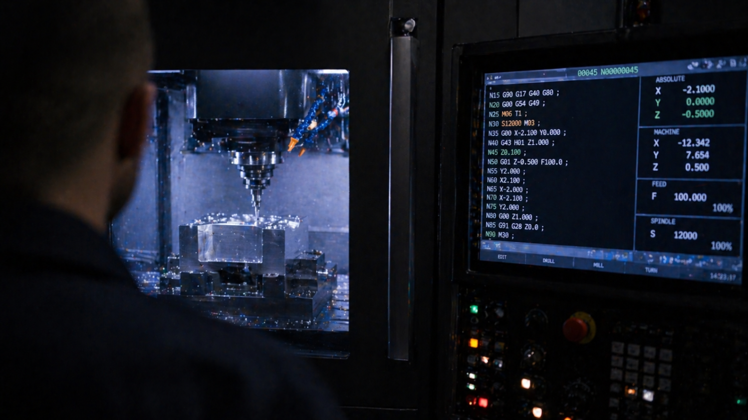
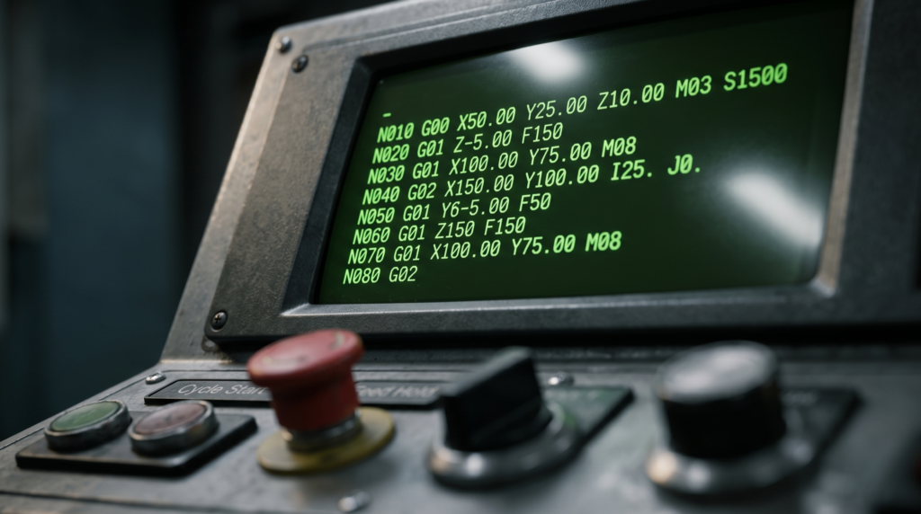
CNC stands for computer numerical control. It is an automated system that manipulates the tool and workpiece using G-code, the foundational language used to guide and command the machine. G-code specifies all operations, including spindle speed, feed rate, and auxiliary functions.

How Does a CNC Machine Work?
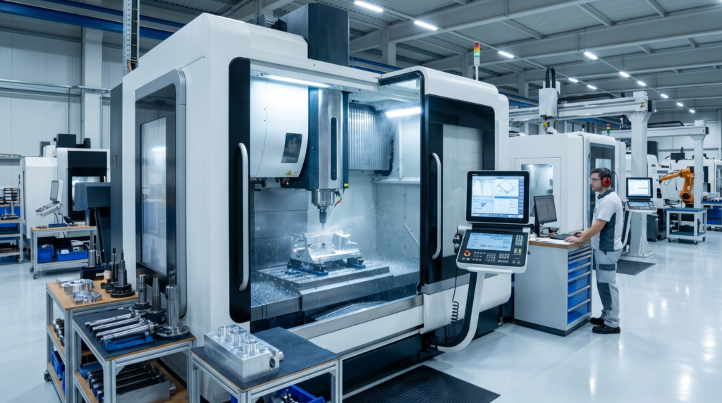
At its core, a CNC machine consists of a maneuverable tool or platform that follows pre-programmed commands. Modern machines use closed-loop control to ensure accuracy, speed, safety, and consistency.
The workflow follows a strict five-step cycle:
- CAD (Computer-Aided Design): The part begins as a 3D CAD model accompanied by a technical drawing that includes all specifications and tolerances.
- CAM (Computer-Aided Manufacturing): The 3D model is translated into toolpaths.
- G-Code Generation: The CAM software outputs the exact alphanumeric G-code required to machine the part.
- MCU (Machine Control Unit): The code is fed to the machine’s control unit.
- Execution: Instructions are implemented using direct-drive stepper or servo motors.
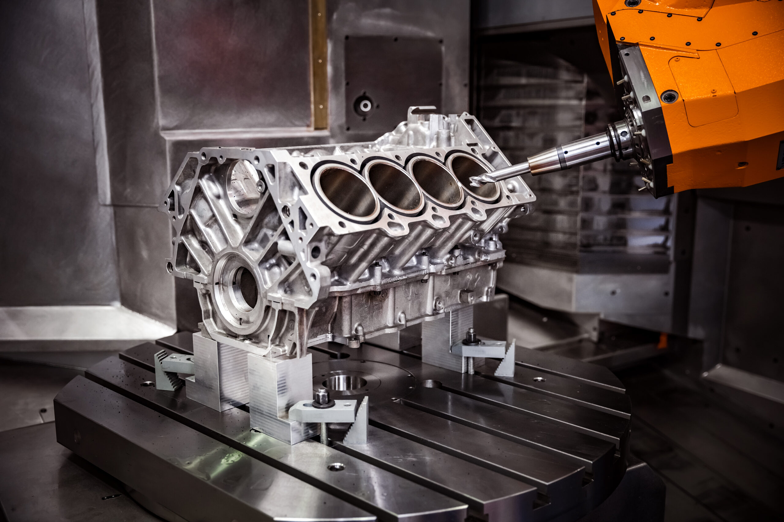
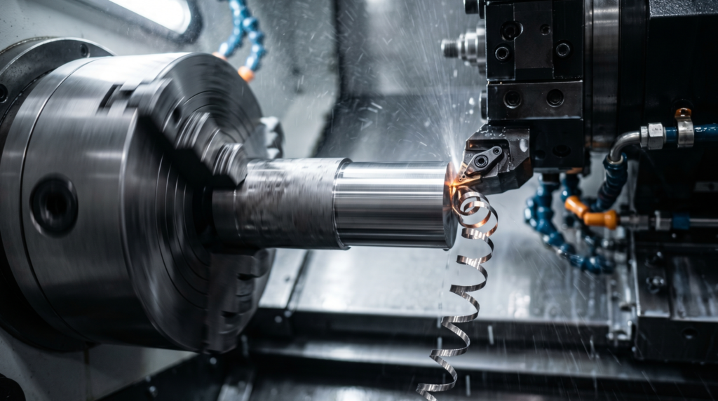
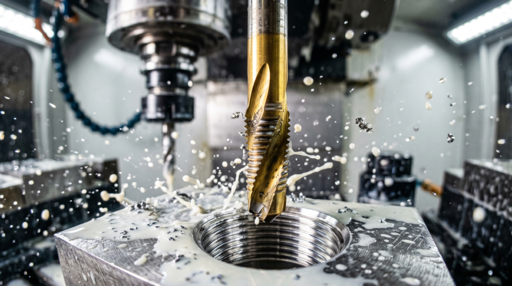
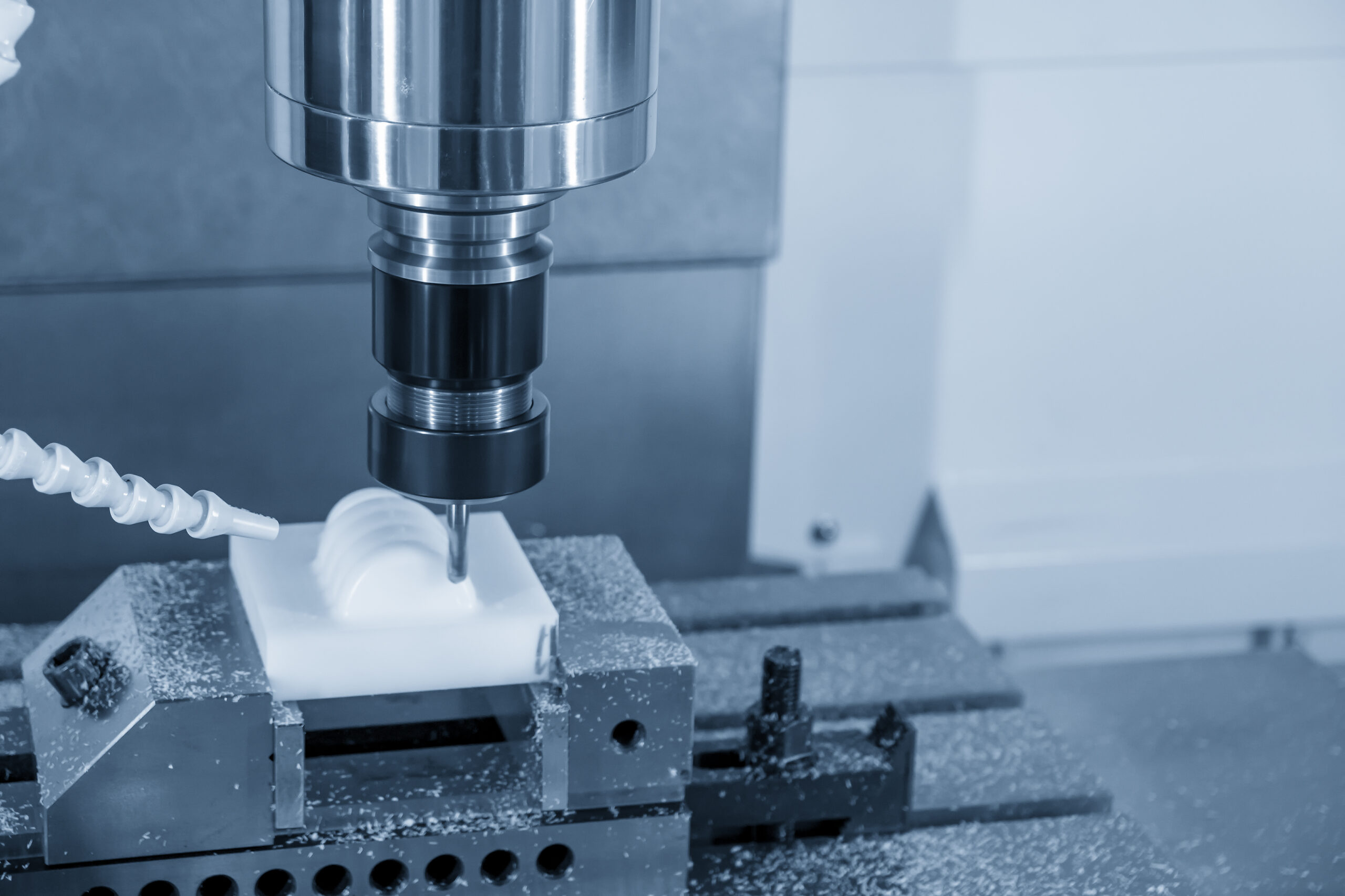
During execution, cutting fluids (high-pressure coolant) are directed into the cutting zone. This thorough chip evacuation reduces heat accumulation, avoids clogging, increases tool life, and enables greater feed rates.
CNC Milling
CNC milling is a subset of CNC machining services.
CNC milling is a high-precision, versatile, and reliable subtractive process capable of machining a wide range of materials, including metals, wood, plastics, stone, and ceramics.
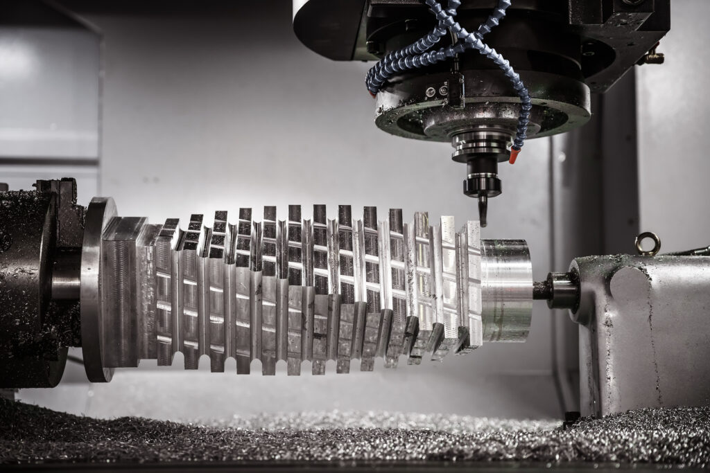
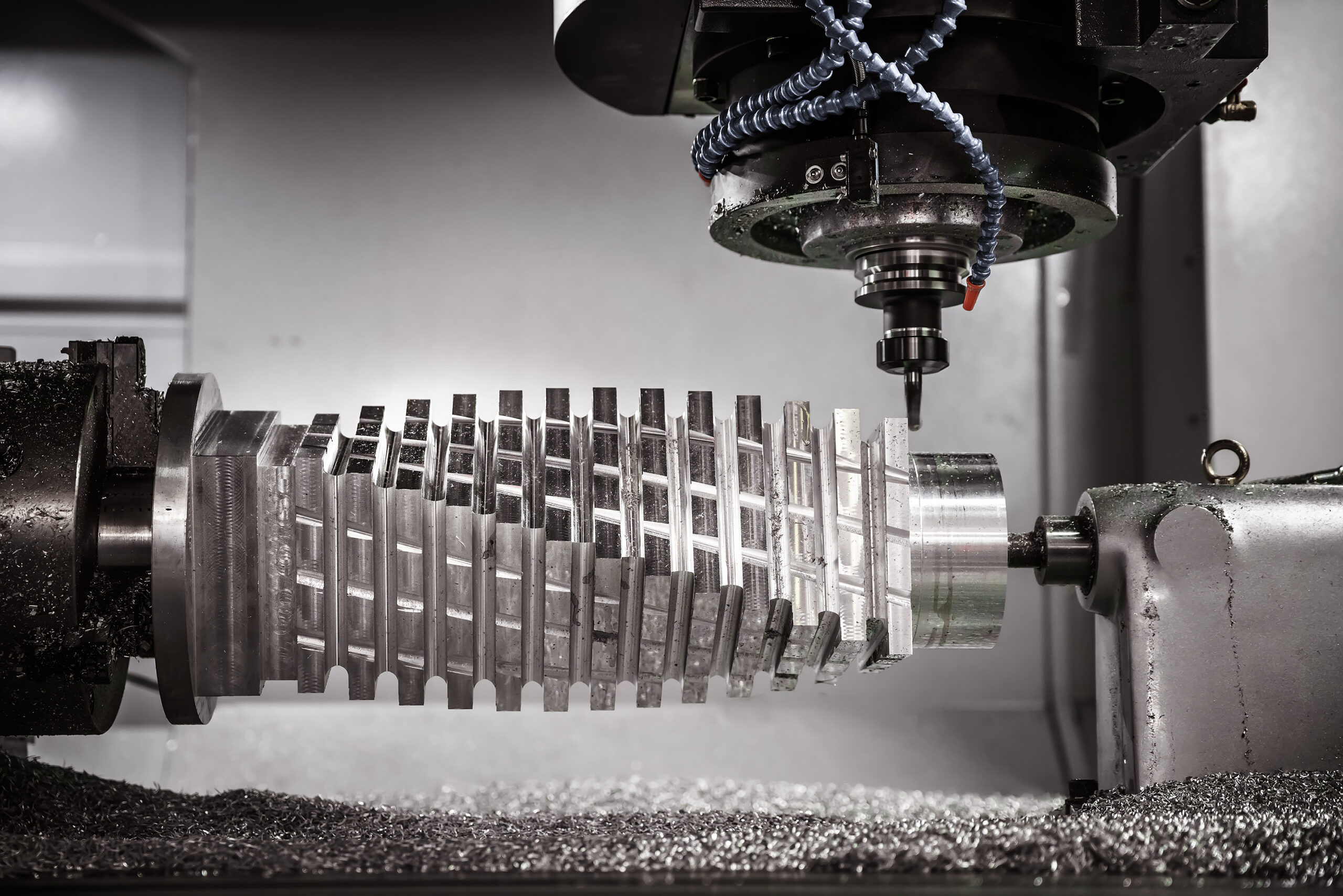
The workstation primarily consists of a worktable where the workpiece is secured, and a spindle head that drives a high-speed, multi-toothed rotating cutter. It is particularly valuable for machining tough metals like titanium and Inconel, making it an extensively used technology in the aerospace, automotive, medical, and energy sectors.
By combining different cutting strategies, engineers can produce highly complex parts. Common operations include:
- Pocketing
- Chamfering
- Boring
- Slotting
- Facing
Axis Classification
The capability of a milling machine is heavily defined by its number of axes. Transitioning from a standard 3-axis to an advanced multi-axis system drastically changes what geometries are possible.
| Machine Capability | Tool Movement & Degrees of Freedom | Best Manufacturing Use Cases |
| 3-Axis Milling | Tool moves along X, Y, and Z axes. | Most common method for 2D/2.5D parts, panels, and enclosures. Lowest cost and easiest setup. Limitation: Restricted tool access. |
| 4-Axis Milling | Adds a single rotational axis (usually A-axis). | Ideal for drilling angled holes and creating helical features (gears, medical implants) without manual repositioning. |
| 5-Axis Milling | Adds two rotational axes to the standard XYZ movements. | Required for tracing continuous, complex curves (impellers, aerospace rotors). Often used in a “3+2” setup to machine 5 sides of a part in one setup. |
| 6-Axis Milling | Adds three rotational axes to XYZ. | Exceptionally rare. Maintains perfect consistency across severe compound curves, but 5-axis usually suffices for most complex jobs. |
Types of CNC Milling Machines
Depending on the orientation of the tool spindle, CNC milling machines are divided into Vertical Machining Centers (VMC) and Horizontal Machining Centers (HMC). Each serves a distinct manufacturing purpose.
VMC vs. HMC Quick Reference
| Feature | Vertical Machining Center (VMC) | Horizontal Machining Center (HMC) |
| Spindle Orientation | Vertical (Top-down) | Horizontal (Side-facing) |
| Primary Use Case | All-purpose, highly versatile shop floor operations. | Specialized, high-volume production of tough materials. |
| Cost & Footprint | Lower initial cost; requires less floor space. | Up to 3x higher cost; requires a massive footprint. |
| Setup & Fixturing | Easier to program; requires less complex fixturing. | Longer setup times; high tooling costs. |
| Throughput & Automation | Requires manual operator intervention to reposition parts. | Machines multiple sides without repositioning; smooth automation integration. |
| Chip Evacuation | Relies on forced coolant to clear chips. | Excellent natural, gravity-based chip flow. |
(Note: HMCs are available as 3-, 4-, and 5-axis systems, though 4-axis is considered the industry standard).

Common Milling Operations Quick Reference
Milling is capable of performing a complete set of operations to take a product from a raw material block to its final form. Some key CNC milling operations include:
| Milling Operation | Technical Description | Best Application |
| Face Milling | Creates flat surfaces perpendicular to the axis of the tool. It needs a large tool diameter. | Ideal for creating smooth, level surfaces from raw stock as an initial operation, or as a final operation to achieve a smooth finish and optimized surface roughness. |
| End Milling | Cuts deep either along the periphery or in the body of the workpiece using edges along the sides and the tip of the tool. | Best for vertical walls, deep, narrow features, and 3D shapes such as pockets, slots, and various profiles. |
| Peripheral (Plain) Milling | The cutting tool’s orientation is horizontal with the cutting edge along its circumference. | Meant for removing a large amount of material quickly and creating large, flat, parallel surfaces efficiently. |
| Angular Milling | The cutting edge meets the workpiece at an angle (like 45°, 60°, 90°) or uses double-edged cutters. | Creates flat angular surfaces like V-grooves in a single approach. |
| Form Milling | Refers to the use of custom-shaped cutters to carve complex profiles in a single pass without multiple tool changes. | Used for convex/concave surfaces, mould cavities, intricate gears, ergonomic shapes, and threads, reducing overall cycle times while maintaining high accuracy and repeatability. |
(Apart from these, CNC milling can also perform operations such as drilling, boring, reaming, thread milling, gear milling, and more).
CNC Turning
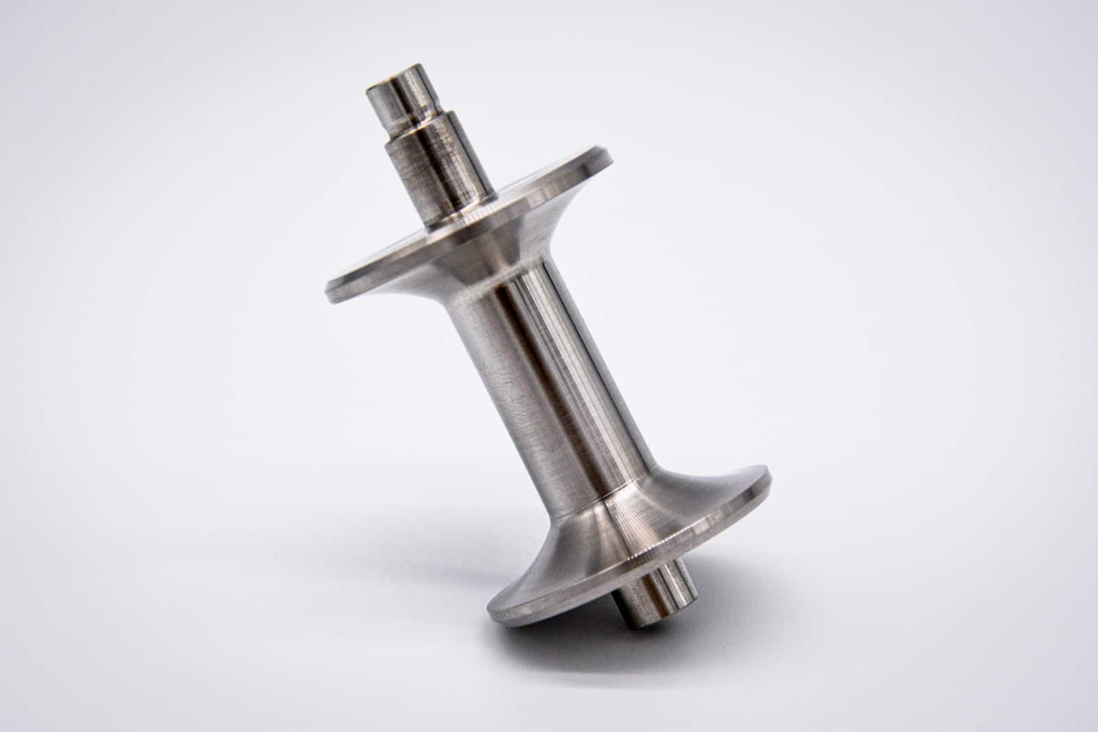
CNC turning is a process where the workpiece is mounted on a rotating chuck (power chuck) and rotated against a stationary single-point tool to machine the workpiece. Because CNC lathes produce radially symmetrical parts, they are ideal for cylindrical and conical components.
Modern CNC turning systems, also known as CNC turning centers, can feature “live tooling”. These centers house additional tools to execute limited milling, drilling, slotting and tapping operations without transferring it to a second machine. The addition of sub-spindles can further reduce or eliminate the need for secondary operations or mid-process workpiece reorientation.

CNC turning also uses G-code and can make fast, precise cuts considerably reducing the time required compared to a manual lathe. The most common CNC turning setup has two axes (X and Z). Newer CNC turning machines often have three or even five axes.
Types of CNC Turning Machines
CNC lathes come in many different configurations. Some have two tool turrets, some two spindles, and some even integrate milling and grinding in the same setup. Seemingly similar machines can vary in horsepower, stock size and tool holding mechanisms. Thus, there are various ways in which we can classify CNC turning machines.
Aspects such as turret orientation (vertical and horizontal), precision (swiss-style) and multi-axis configurations (2, 3, 4, 5+ axes) are popular when categorising lathe configurations:
| Lathe Configuration | Key Characteristics & Use Cases |
| Horizontal Turret Lathe (HTL) | Represents the majority of CNC turning machines. Features high accuracy and repeatability, maintaining tight CNC machining tolerances at the micron-level over large production runs. The simplest two-axis setups machine simple parts fast and reliably. |
| Vertical Turret Lathe (VTL) | Consists of a vertical turret. Best used for heavier components, as gravity helps stabilize the part rather than working against it. |
| Multi-Axes CNC Lathe | Classified by independent, controllable axes (2, 3, 4, 5, and 6-axis systems). Simultaneous movement offers more freedom to produce intricate parts in one setup. |
| Swiss-Type CNC Lathe | Specific to making small components with high-level precision. Excellent for high-volume production of complex parts with quick turnaround times. |
Common Turning Operations
CNC turning, while limited to rotationally symmetric parts, can still perform a myriad of operations to take parts from raw stock to a finished product in a single session. Let us look at some of these popular operations:
| Turning Operation | Execution & Tool Movement | Purpose & Application |
| Turning (Straight and Taper) | In straight turning, the tool moves parallel to the axis of the workpiece. In taper turning, the tool moves at an angle to the workpiece’s axis. | Creates straight cylindrical shapes or tapered conical outer surfaces on circular parts. |
| Facing | The tool’s movement is perpendicular to the axis of rotation. | Creates a flat surface at the end of the workpiece. Useful for bringing the part length to required dimensions before giving the end a smooth finish. |
| Drilling & Boring | Creates a precise, centered, axial hole on the end face of the workpiece. The holes are concentric and square to the workpiece’s face. | Drilled holes may be enlarged later to reach the required diameter in a subsequent operation known as boring. |
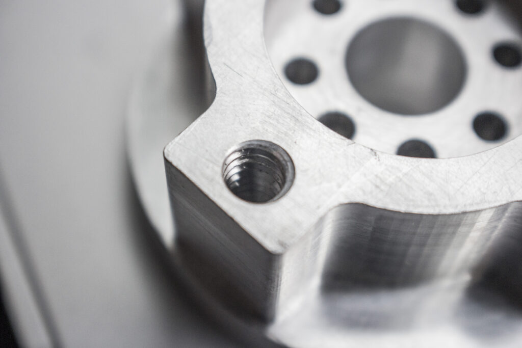
| Tapping & Threading | Tools cut specific helical grooves into the material. | Both operations create threads on a workpiece but differ in location: Tapping creates internal threads whereas threading is used for external threads. |
| Knurling | A cold-forming operation that presses hardened rollers against a metal surface at low speed and high feed. | Creates a texture on a metal surface to improve grip (e.g., gym barbells) and/or for aesthetic appeal. Requires sufficient lubrication to control heat buildup. |
CNC Mill-Turning
CNC machines with both milling and turning capabilities are known as CNC mill-turning or CNC turn-milling machining centers. These machining centers are more versatile than either CNC turning or CNC milling as they combine the two processes into one. Note that they are not the same as CNC turning centers with live tooling.
CNC mill-turning centers are true multi-tasking machines designed equally for turning and milling. They have features like a full Y-axis standard, dual spindles, advanced C-axis control, and multiple turrets. They also come in four-axis and five-axis alternatives. As a result, they have advantages such as better rigidity, milling performance and axis control making them more suitable for complex profiles.
CNC Mill-Turning Operations
Common operations in CNC mill-turning are the same as those seen in CNC milling and CNC turning machines. However, the unique configuration of CNC turn-mills enables engineers to complete complex operations in one setup. Also, they can perform advanced operations that are not possible with either standard CNC milling or CNC turning machines:
| Mill-Turn Operation | Technical Execution | Engineering Benefit & Application |
| Synchronised Pinch Machining | Two tools engage the part on opposite sides simultaneously. | Cancels out cutting forces. Prevents long, slender shafts from deflecting or breaking under pressure. |
| Y-Axis Off-Center Machining | Utilizes the Y-axis to mill features parallel to, but offset from, the centerline. | Highly accurate positioning for keyways, flats, and off-center holes around a cylinder’s circumference. |
| B-Axis Angular Milling | The milling spindle rotates to cut at any angle while the workpiece turns. | Machines tapered holes or angled pockets without requiring custom, complex fixtures. |
| Back-Side Machining | The part is automatically handed off from the main spindle to the sub-spindle. | Allows both the front and back face of a part to be machined without manual operator flipping. |
| Polygon Turning | Exact ratio synchronization between the workpiece rotation and milling cutter rotation. | Creates hexagonal shafts, square bolt heads, and wrench flats without requiring secondary broaching operations. |
CNC Grinding
CNC grinding machines also exist as standalone machines. They use abrasive wheels to remove material with extreme precision and create ultra-smooth surface finishes within an accuracy of a few microns. The smoother finishes also promote uniform wear and reduced friction, extending part life and efficiency in applications.
These specialized grinders reduce human error and deliver highly repeatable results required in precision industries such as aerospace, automotive and medical to meet tight CNC machining tolerances. CNC grinding machines offer greater productivity through multi-axis control, real-time adjustments and automated operations.
Types of CNC Grinding Machines & Operations
While all grinding machines perform the same function of precisely removing material, there still exists a variety of CNC grinding machines based on factors such as the type of surface they grind (internal vs. external), workholding method (center vs. centerless), and surface profile (flat vs. round).
| Grinding Method | Target Geometry | Technical Execution & Best Use Case |
| Surface Grinding | Flat, planar surfaces | Smooths and levels flat profiles. Can achieve extreme accuracies up to ±0.002 mm (0.00008 in). |
| Cylindrical Grinding | External and internal cylinders | Holds the part between chucks and rotates both the part and the grinding wheel in opposite directions for high-speed material removal. |
| Centerless Grinding | Pins, rods, and long shafts | Grinds cylindrical workpieces without clamping them in a chuck. Ideal for high-volume, continuous production. |
| Tool & Cutter Grinding | Cutting tool flutes and edges | Specialized process used strictly for the fabrication and resharpening of CNC cutting tools. |
CNC Drilling
While a drilling operation can be integrated into CNC milling and turning systems, it can also exist as a standalone CNC drilling machine. This is especially useful for products that require operations like drilling, tapping, reaming and countersinking in mass production environments.
Sheet metal parts in automotive and related sectors often employ standalone CNC drilling machines as this is fast and more efficient when we need a large number of holes with minimal complexity.
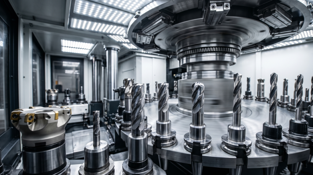
Tooling
Tooling refers to cutting implements, holders and workholding accessories used in CNC systems to hold and cut the raw materials into finished parts. They come in many types, depending on the type of CNC machine, and are suited to specific needs to create different features on the parts.
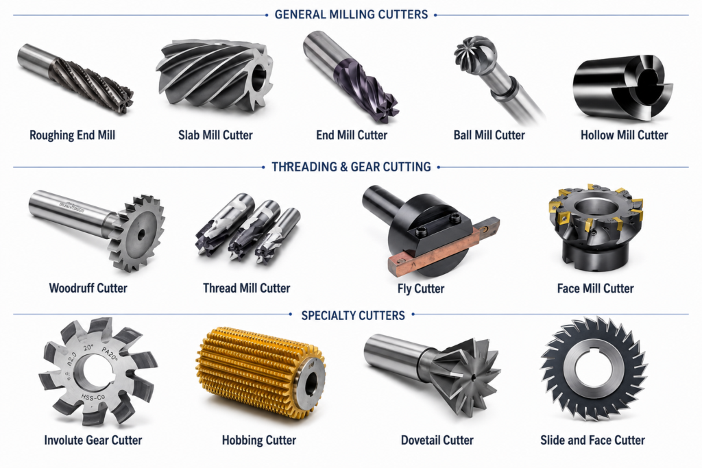

CNC Milling Tools
- End Mill: An end mill is the most common type of tooling and can typically cut in 3 directions. They come in various styles such as flat, corner radius, roughing, ball and taper to name a few. They are characterised by the number of flutes, helix angles, base material and coating material.
- Face Mill: A face mill is designed to cut across a large surface area, i.e. facing. Its cutting edges are typically on the edge of the tool and the teeth are usually carbide inserts.
- Thread Mill: A thread mill is designed to create threads. It works by rotation around the shank in a helical pattern to cut in the thread shape.
- Slotting Cutter: These types of cutters are used to create t-slots along the length of a part. The tool must enter and exit from an open side of the material due to its geometry.
Lathe Tools
- Turning Inserts/Tools: Used to cut the outer diameter of the part. Available as solid tooling ground to shape, or more commonly as replaceable carbide inserts mounted in a tool holder.
- Boring Bars: Long, slender tools that reach inside a drilled hole to enlarge it to a precise diameter and finish. Also used for internal grooving and threading.
- Parting Tools: Narrow blade-like tools used to cut off the finished part from the bar stock as a final operation.
- Drills: Used to create axial holes in the end face of the workpiece. The holes are typically enlarged afterward by boring or reaming to reach final tolerances.
Tooling Material
The different tool types can be subdivided by their base materials. The materials typically used for tooling are listed below:
| Tooling Material | Characteristics & Performance |
| High Carbon Steel | These are the cheapest type of machine tool but do not have a long tool life. They also lose their hardness at around 200 °C. |
| High-Speed Steel (HSS) | These are more common than carbon steel tools as they have a longer tool life and only lose their hardness at 600 °C, meaning they can cut at higher speeds. |
| Carbide Inserts | Cemented carbide tools are harder than HSS but are less tough and can fracture if not handled correctly. Uncoated carbide can withstand temperatures of up to 900 °C whereas coated grades (TiAlN, etc.) can tolerate even higher temperatures. |
| Ceramics | These cutting tools are extremely hard and are usually reserved for cutting hard materials like hardened steels or cast iron at very high temperatures. There are two common variants namely alumina and silicon nitride. |
| Cubic Boron Nitride (CBN) | These tools are ideal for hardened steels and superalloys and have excellent abrasion and thermal resistance. |

Manufacturing Capabilities
CNC machining is a versatile process that can cater to different manufacturing setups efficiently. It is excellent for prototyping and low-to-medium volume production. If certain conditions are fulfilled, CNC machining can also do well at high-volume production.
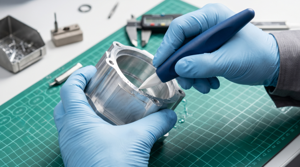
Prototyping
CNC machining is widely used for prototyping because the prototype is made from the actual production material with real mechanical properties, accurate dimensions, and a good surface finish. This makes it suitable for functional testing, not just fit checks.
Also, machining is very flexible, making it available for producing a wide range of geometries. 3D printing can be a better and cheaper option when the geometry involves internal channels or complex profiles that would be impractical to machine, or when material properties are less critical.
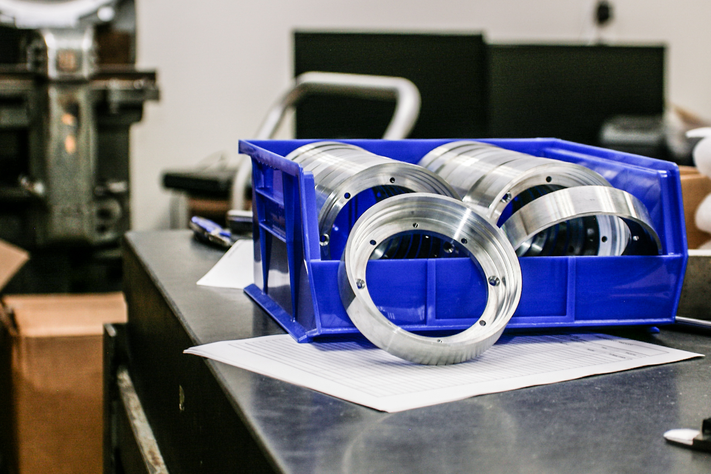
Low-Volume Production
The most important aspects to consider when selecting a manufacturing technology for low-volume production (10-1000 units) are lower initial tooling costs, higher design flexibility, and fast turnaround times. CNC machining does not require custom-made dies which lowers initial tooling costs. It also provides fast turnaround times and higher design flexibility through programmable automation.
However, CNC machining may not be the best option if the geometry is very complex, setup costs are high, or there is excessive material waste (think about the boundary box of your part, all besides the final shape is waste). In such cases, it is more prudent to consider alternatives like 3D printing and casting.
High-Volume Production
When we shift to high volume production (>1000 units), the priority changes to a fine balance between quality consistency, unit cost, and production speed. CNC usually does not make a great contender for these requirements due to longer process durations and higher per-part cost. Other aspects like complex internal features, excessive material waste, and very high volumes further reduce CNC’s competitiveness.
Extremely simple designs are also better served by simpler and faster manufacturing processes like casting, stamping and injection moulding, especially if the raw materials are also cheap. The only scenarios where CNC machining provides a better cost-benefit ratio in high volume production is if there are tight tolerances, hard raw materials, frequent design changes, and a mix of different products (different sizes).
Pros and Cons of CNC Machining
The scenarios above highlight CNC machining’s suitability for different production volumes. This suitability comes down to the advantages and disadvantages of CNC. Having a good grasp of that will enable better decision-making regarding manufacturing method choices, and whether CNC should be considered or not.
Pros of CNC Machining
The fact that CNC machining plays a central role in manufacturing is a direct consequence of the following advantages it brings to the table:
- Extreme precision and tight tolerances: Standard CNC machining can routinely achieve tolerances up to ±0.005 in (±0.127 mm), while precision applications may reach ±0.0005 in (±0.0127 mm) using CNC machining tolerances. Specialized ultra-precision machining processes can achieve tolerances in the micron range under tightly controlled conditions.
- Complex geometries: The advanced 4-axis and 5-axis systems are capable of producing highly complex geometries like turbine blades, impellers, and organic profiles with remarkable accuracy.
- Vast material choice: CNC machining works with many metals, plastics and composites. It is particularly useful for machining tough metals like titanium and Inconel which are difficult to machine using conventional methods. Some popular materials for CNC machining are aluminum, brass, stainless steel, PEEK and ABS.
- High repeatability: Automated machining eliminates human error and associated variance in the finished products. Once a program is set, the produced parts are dimensionally consistent.
- Highly productive: A fully automated CNC machining system can work continuously with minimal operator intervention. CNC systems are run in a lights-out setup to reliably produce a high number of parts in a short span.
- High quality final surface: CNC machining can achieve excellent surface finish in a single pass reducing the need for post-processing operations.

Cons of CNC Machining
Also, there are some limitations that need to be taken into account when deciding whether CNC is truly the best option for production:
- High initial investment: A CNC machine is expensive equipment. The cost of purchase for a standard 5-axis CNC machine that machines tough materials can often run into hundreds of thousands of dollars. Additionally, there’s the cost of maintenance involving items like software, tooling, maintenance and skilled personnel.
- Need for skilled operators: Modern CNC machines need highly skilled operators to write, execute and monitor CNC programs. An incompetent CNC machinist can make costly mistakes like tool breakage, machine damage and scrap parts.
- Part size limitation: CNC machining size limitations are determined by the working envelope of a CNC system. Very large parts cannot be produced on standard machines and would need specialized “large format” CNC machines.
- Material wastage: On account of CNC machining being a subtractive manufacturing process, some amount of material wastage is inevitable. However, for parts that require extensive material removal, alternate options like casting and additive manufacturing would have less material wastage.
- Design geometry restrictions: Some features such as enclosed internal channels and cavities can be difficult or impractical to produce using conventional CNC machining because the cutting tool must have physical access to the machining area. Sharp internal corners cannot be achieved either due to the round cross-section of the tool. There will always be an internal radius, albeit it could be made smaller.
- Not suitable for large production runs: CNC becomes ineffective at high-volume production. Alternatives like injection moulding and casting provide faster production and lower material wastage for large batches.
CNC Machining Materials
CNC machining supports a very wide variety of materials – metals, nonmetals and composites. Each category includes materials with widely varying properties. In this section, let us review some of the most popular materials under different categories when it comes to CNC machining.

Metals
While many metals work great with CNC machining, those with better machinability, excellent mechanical properties, corrosion resistance, easy availability and lower raw material cost offer greater value. Due to these reasons, the following metals are often best suited for use with CNC machining:
| Metal Type | Machining Characteristics & Applications |
| Aluminum | CNC machining is the go-to method for aluminum parts for reasons such as high machinability, lower cost and a better strength-to-weight ratio. Aluminum and its alloys are often the default materials for CNC machining for general-purpose applications as well as rapid prototyping. |
| Steel / Stainless Steel | Mild steel and stainless steel (304, 316) are often used to fabricate structural parts via CNC machining. The primary reasons for this are their high strength, long lifespan, wear resistance and reliability. |
| Titanium | Titanium has a tendency to work harden and cause rapid tool wear. CNC machining mitigates this by optimising cutting parameters, enhancing heat dissipation and maintaining sharp tools. These steps ensure that the titanium cuts cleanly rather than smearing. |
| Brass | CNC machining works great for brass given that it is easy to machine. It is ideal for low-friction applications and electrical components. |
| Copper / Silver | Copper and silver are also suitable CNC machining materials where good electrical and thermal conductivity is a requirement. |
(Other metals frequently machined by CNC include bronze and superalloys).

Non-Metals
CNC can excel at machining non-metals as they’re softer than metals. Machines can use faster speeds, higher feeds and achieve a superior surface finish. The tools also last longer due to reduced wear.
Wood
Woods such as hardwood, softwood and plywood are machined using CNC systems to create furniture components, architectural millwork, complex cabinetry and 3D-carved items.
Plastics
CNC machining is popularly used to create high precision parts from plastic materials.

The process is highly effective and affordable and is typically used for prototyping, functional testing and low-to-medium volume production.
| Plastic Material | Machining Characteristics & Material Properties | Typical CNC Applications |
| ABS | Affordable, impact-resistant, and highly machinable. | Electronic enclosures, rapid prototyping, and structural components. |
| Acrylic / PMMA | Rigid, brittle, and optically clear; requires sharp tools to avoid chipping. | Light pipes, transparent display lenses, and fluidic devices. |
| Nylon 6 / PA 6 | Strong and highly wear-resistant; absorbs moisture, which can affect tight tolerances. | Gears, bearings, wear pads, and heavy-duty rollers. |
| PC (Polycarbonate) | Extremely tough with high impact strength; can be vapor-polished for near-optical clarity. | Fluidic manifolds, transparent protective covers, and impact-resistant housings. |
| PEEK | High-performance thermoplastic; exceptional thermal, chemical, and mechanical stability. | Aerospace components, medical implants, and high-temperature valves. |
| PEEK glass-filled | Highly rigid and abrasive to cutting tools; offers superior structural strength at high temperatures. | High-stress electrical insulators and structural aerospace brackets. |
| POM / Delrin acetal | The most machinable plastic; dimensionally stable with naturally low friction. | Precision gears, bushings, sliding mechanisms, and custom fixtures. |
| Polypropylene (PP) | Excellent chemical resistance and fatigue strength; soft and prone to melting if feeds/speeds are incorrect. | Chemical tanks, medical device components, and living hinges. |
| PTFE / Teflon | Ultimate low-friction surface and chemical resistance; very soft, making tight tolerances difficult to hold. | Gaskets, chemical-resistant seals, and electrical insulators. |
| UHMW PE | Extremely tough with incredible abrasion resistance; deforms easily under heavy clamping pressure. | Conveyor guide rails, chute linings, and industrial wear strips. |
Foam
Foam is also an excellent raw material for CNC machining. It is generally used to create detailed models and rapid prototyping parts. Popular foams used with CNC machining are HDU, EPS, PU, EVA and polyethylene.
Composites
Composite materials combine two or more materials, typically reinforcing fibres and a matrix material, to create a high strength material for special applications. CNC-based composite parts are often seen in sectors such as aerospace and automotive where a high strength-to-weight ratio is a precondition.
Composite materials are abrasive, brittle and layered. CNC machining uses specific techniques like hardened cutting tools, high speed operation and strict chip control to machine popular composites like carbon fibre reinforced polymer (CFRP), glass fibre reinforced polymer (GFRP), aramid fibre reinforced polymer (AFRP) and metal matrix/ceramic composites.
CNC Tolerances
Tolerances in CNC machining play a very important role. General-purpose CNC machines can typically meet tolerances of 0.005 to 0.01 inches (0.125 mm to 0.25 mm). However, specialized equipment can achieve up to 0.00008 inches (0.002 mm) of resolution through a combination of high-rigidity structures, climate control, sub-micron linear encoders, vibration isolation, and advanced tool monitoring. Such ultra-precision is common in aerospace and medical components.

To make use of these capabilities, design for CNC machining extensively uses tolerance systems like GD&T, a universal design language used by engineers and machinists to convey design intent clearly and avoid errors and rework. GD&T ensures a well-fit assembly especially for complex, high-accuracy and interchangeable parts. Competent use of GD&T helps define permissible variation in form, location, and orientation of a part’s features.
The correct tolerance limit for a part depends on the part’s functional requirement, material properties, the chosen CNC process, and the balance between cost and precision.
Three levels of tolerances are generally seen in CNC machining:
| Tolerance Level | Typical Range | Application & Cost Impact |
| Standard | ±0.005 in (±0.125 mm) | The baseline for most non-critical parts. Fulfills functional needs without inflating manufacturing or inspection costs. |
| Tight | ±0.001 in (±0.025 mm) | Necessary for critical fits like high-speed rotating assemblies, sealing grooves, and bearing bores. Cost can increase up to 5x. |
| High-Precision | Up to 0.000004 in (0.1 µm) | Used for ultra-precision optics and satellite mirrors. Requires strict climate control, grinding, and lapping. Typical examples include telescope mirrors, laser optics, and satellite imaging mirrors. These processes are highly sensitive to temperature changes and often utilize grinding or lapping to achieve such precise results. |
Finishing & Post-Processing
Surface finishing refers to the condition of a part’s surface. It is a broad term that encompasses several aspects of a surface, such as its roughness, appearance, texture, and coating. It may also refer to a finishing process that alters the shape, dimensions and look of a machined surface to meet desired specifications.
Common methods to achieve the various finishes for CNC machined parts are mechanical finishing, chemical/electrochemical finishing and coating.
Surface Roughness
The quality of surface roughness is measured by what is called the “average surface roughness” (Ra). It measures the average deviation of the surface profile from the centerline. A smaller value represents a smoother surface.
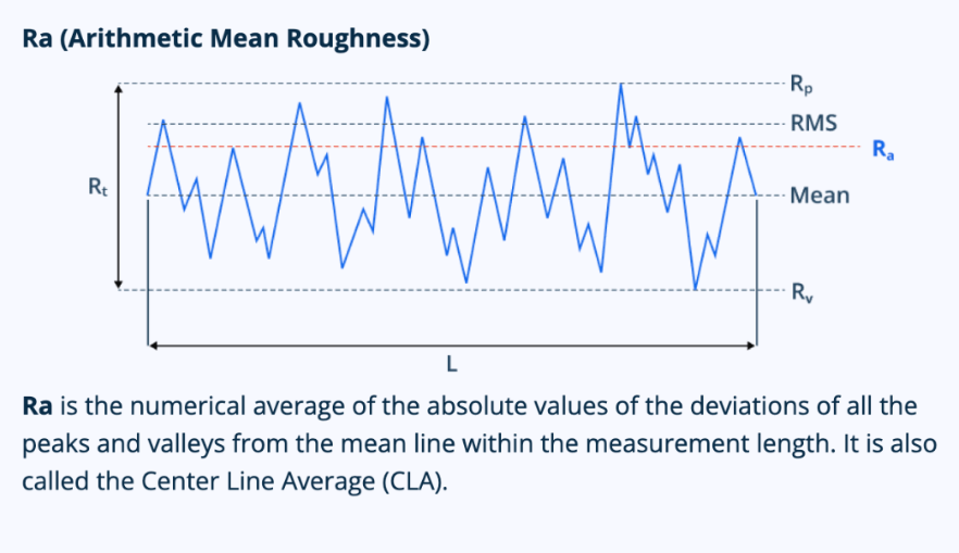
Four common values of surface roughness are generally seen in the industry. These are 3.2 µm (125 µin), 1.6 µm ( 63 µin), 0.8 µm (31.5 µin) and 0.4 µm (15.75 µin). As we go from a rougher to a smoother Ra value, the cost and time involved with part production increases.
Roughness as machined refers to the standard roughness of parts as they exit the CNC machining process. The Ra value of these parts is typically 3.2 µm (125 µin), and the parts still contain cut marks from contact with the cutting tools. We can reduce the Ra value to 1.6 µm, 0.8 µm or 0.4 µm with extra finishing passes.
The advantages of as-machined finish are part consistency, tighter tolerances, and no extra costs. The disadvantages include visible tool marks, reduced corrosion resistance and wear resistance. These types of parts are recommended for structural or tightly-toleranced parts where the appearance is not a prime concern.
Heat Treatment Options
Many CNC machined parts are heat-treated before putting them into service. Some common heat treatment processes for these parts include:
| Process | Technical Execution & Application |
| Quenching (Hardening) | Heats the material to a high temperature followed by rapid cooling in air, oil or water to appreciably improve hardness for tool steels and gears. |
| Case Hardening | Only hardens the outer shell of a part to create a wear-resistant outer layer while the inner core remains ductile and tough. |
| Tempering | Heats the material to a temperature below lower critical temperature, soaking for a few hours followed by cooling in air. Reverses brittleness, internal stresses and recovery of lost toughness from the quenching process. |
| Annealing | Heats the material to a specific temperature and cooling it in the furnace to relieve internal stresses and restore ductility. |
| Normalising | Heats the material to a specific temperature but cooling in air to improve final part strength. |
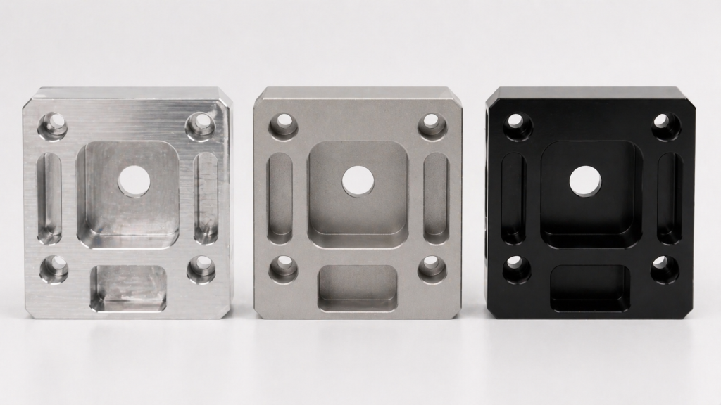
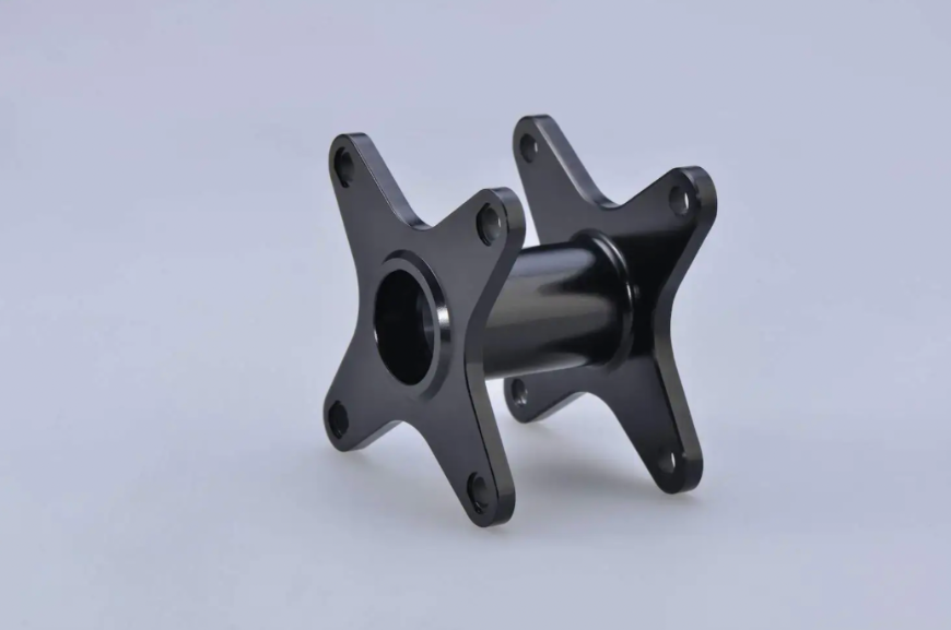
Coating
Coating is often performed on CNC machined parts to improve properties such as corrosion resistance, wear resistance, appearance, surface finish, and increase durability.
Popular methods include:
| Coating Method | Technical Process | Key Benefits & Applications |
| Anodising | Electrochemical reaction that converts the outer metal surface into a durable, anodic oxide finish. | Creates a thin, hard, protective layer. Primarily used for aluminum and titanium parts. |
| Electroplating | Uses an electrical current to deposit a thin layer of a different metal (e.g., nickel, chrome, gold). | Imparts specific properties like high corrosion resistance, electrical conductivity, or a premium cosmetic appearance. |
| Powder Coating | Applies a dry, free-flowing, finely ground thermoset powder that is then cured under heat. | Creates a thick, highly durable protective layer. Available in over a thousand custom color shades. |


5 Design Rules to Keep in Mind
As we’ve already covered, machining is an extremely capable process that can produce very precise components allowing for a lot of flexibility in design. Making use of all these possibilities can end up very costly, though. So it’s best to be aware of the pitfalls that can drive up the costs unnecessarily.
Design for a CNC Machine
Design principles for CNC machining have to consider the capabilities and limitations of these machines. For instance, internal sharp corners, very thin walls, complex internal structures and curved holes are difficult or impractical to produce with standard CNC machines. Tall features, deep cavities and extremely small features should be minimised because they require long, delicate tools prone to vibration and deflection. Even commonplace features such as decorative fillets and chamfers should be avoided, unless functionally necessary, to control costs. Designers should take advantage of CNC machining for parts that need complex 5-axis geometries, micron-level tolerances, precise mating surfaces, design flexibility, accurate concentricity, and high-quality surface finishes.
Do Not Overtolerance
Tolerance all critical features but do not make them tighter than necessary. In the absence of instructions, standard tolerance of ±0.005 in (±0.125 mm) will be held.
Keep Aesthetics to a Minimum
Focusing on aesthetics is one of the fastest ways to inflate the costs of CNC machined parts. This includes excessive numbering/lettering. Use deeper engraving only if necessary. Both of these can be carried out more efficiently as post-processing tasks. Use standard surface finish as your default.
Design for Fewer Setups
Ideally, part features should be designed so they can be machined from a single tool access direction. This minimises the need for multiple setups, reorientation and refixturing which significantly increase machining time, complexity and dimensional misalignment risk. If designers cannot limit machining orientation in this way, manufacturers may be forced to use multi-axis CNC machines, unnecessarily increasing manufacturing complexity and cost.
Use Standard Hole and Thread Sizes
Avoid custom tooling by using standardised drill and tap sizes. Also limit thread depth.
The Value and Future of CNC Manufacturing
CNC machining is still a highly effective, modern technology capable of producing precise, high-performance parts.
While CNC may not be the most economical option for high-volume production, it remains a top choice in the manufacturing industry for prototyping, low-to-medium volume production and high-performance engineering needs.

Comment(0)