 Europe
  Türkiye
  United Kingdom
  Global


 0
0
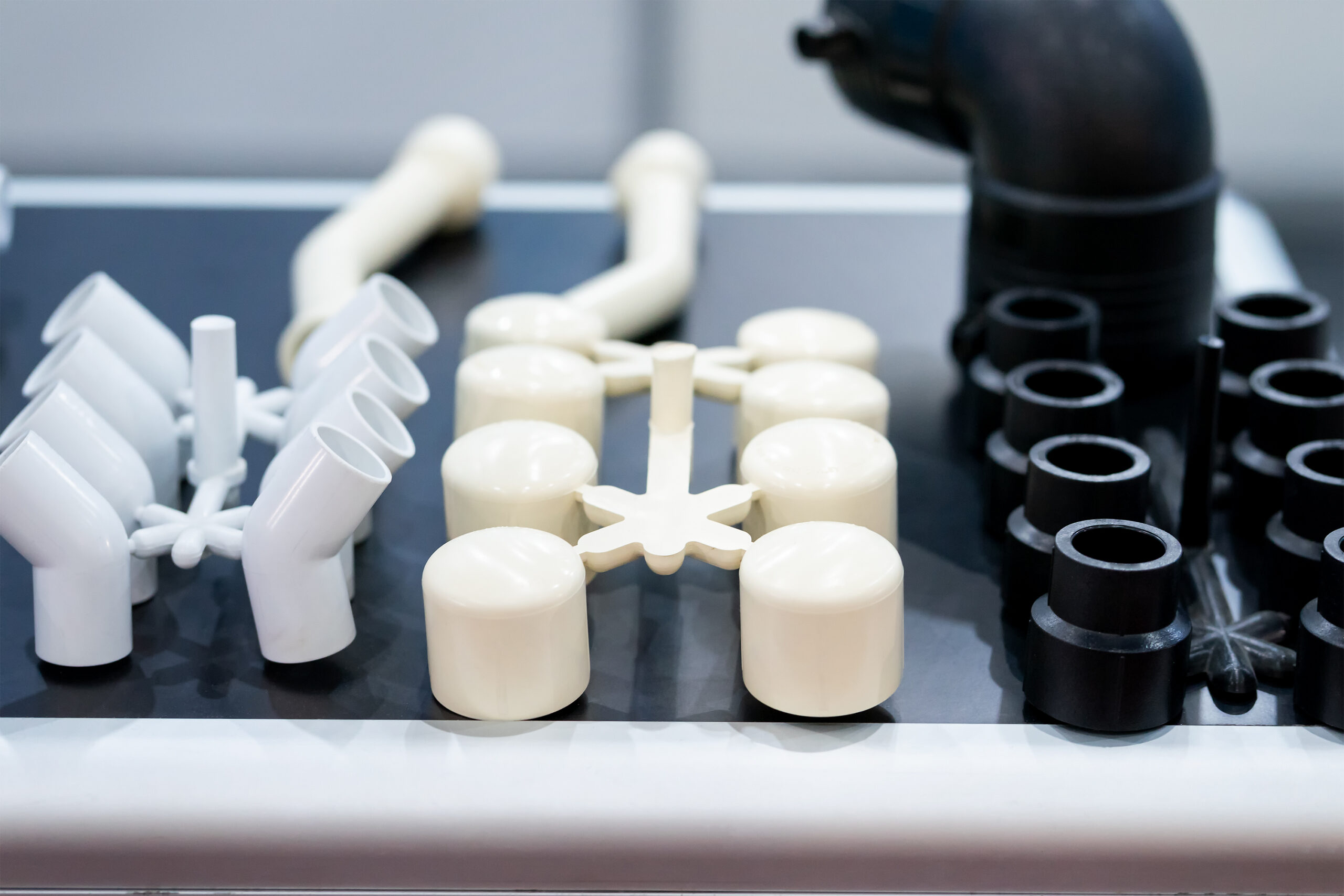
While high-performance plastics unlock new capabilities in lightweighting, durability, and biocompatibility, they introduce non-obvious moldability tradeoffs that can derail part production.
Unlike commodity plastics designed for high-volume parts with modest mechanical or thermal demands, high-performance plastics require careful selection, molding, and validation for function-critical applications. Engineers must evaluate them not only for strength or resistance, but also for moldability, thermal behavior, and interaction with the molding environment.
Comparison of Key High-Performance Plastics for Injection Molding
The table below groups leading high-performance plastics used in injection molding according to their mechanical properties, chemical resistance, and molding difficulty.
| Material | Temp Resistance | Chem Resistance | Strength (σT) | Flowability (MFR) | Modulus (E) | Flame Retardancy | Molding Complexity | Use When… |
| PEEK | ★★★★★ (HDT 160 °C; Tg 143 °C) | ★★★★★ | ★★★★★ (σy ≈ 95 MPa) | ★★☆☆☆ (MFR ≈ 3 g/10min @400 °C) | ★★★★★ (E ≈ 3.8 GPa) | ★★★★★ (UL 94 V-0) | ★★★★★ (Tm 343 °C) | High strength, high temp, chemical resistance (e.g. aerospace, pumps) |
| PAI | ★★★★★ (HDT >270 °C) | ★★★★☆ | ★★★★★ (σy ≈ 120 MPa) | ★★☆☆☆ (MFR ≈ 4 g/10min @370 °C) | ★★★★★ (E ≈ 5.5 GPa) | ★★★★★ (UL 94 V-0) | ★★★★★ (Tm ≈ 305 °C) | Extreme thermal + mechanical loads (e.g. seals, bearings) |
| LCP | ★★★★☆ (HDT ≈ 230–240 °C) | ★★★★☆ | ★★★★☆ (σy ≈ 90 MPa) | ★★★★★ (MFR ≈ 12–20 g/10min) | ★★★☆☆ (E ≈ 2.2 GPa) | ★★★★☆ (UL 94 V-0) | ★★★★☆ (Tm ≈ 280–300 °C) | Miniaturized, thin-wall precision parts (e.g. RF connectors) |
| PEI | ★★★★☆ (Tg 217 °C) | ★★★★☆ | ★★★★★ (σy ≈ 110 MPa) | ★★★☆☆ (MFR ≈ 10 g/10min @370 °C) | ★★★★☆ (E ≈ 3.2 GPa) | ★★★★★ (UL 94 V-0) | ★★★★☆ (Amorphous; no Tm) | Medical/electronic housings, stable at heat + humidity |
| PSU | ★★★☆☆ (HDT ≈ 174 °C) | ★★★★☆ | ★★★★☆ (σy ≈ 70 MPa) | ★★★☆☆ (MFR ≈ 15 g/10min) | ★★★☆☆ (E ≈ 2.4 GPa) | ★★★☆☆ (UL 94 V-1) | ★★★★☆ (Amorphous) | Transparent, steam-resistant devices (e.g. medical, labware) |
| PPS | ★★★★☆ (HDT ≈ 220 °C) | ★★★★★ | ★★★★☆ (σy ≈ 85 MPa) | ★★★☆☆ (MFR ≈ 15 g/10min @315 °C) | ★★★★☆ (E ≈ 3.4 GPa) | ★★★★★ (UL 94 V-0) | ★★★☆☆ (Tm ≈ 285 °C) | High rigidity + chemical exposure (e.g. sensors, battery packs) |
| PA (High-Perf) | ★★★☆☆ (HDT 120–150 °C) | ★★★☆☆ | ★★★☆☆ (σy ≈ 80 MPa) | ★★★★☆ (MFR ≈ 20–30 g/10min) | ★★★★☆ (E ≈ 2.8–4 GPa) | ★★★☆☆ (UL 94 HB/V-2) | ★★★☆☆ (Semi-crystalline) | Cost-effective strength (e.g. gear housings, mounts) |
| POM | ★★★☆☆ (HDT ≈ 110 °C) | ★★★☆☆ | ★★★★★ (σy ≈ 65–75 MPa) | ★★★★☆ (MFR ≈ 12–25 g/10min) | ★★★★☆ (E ≈ 2.7 GPa) | ★★☆☆☆ (UL 94 HB) | ★★☆☆☆ (Tm ≈ 175 °C) | Low-friction, precision parts (e.g. bushings, slides) |
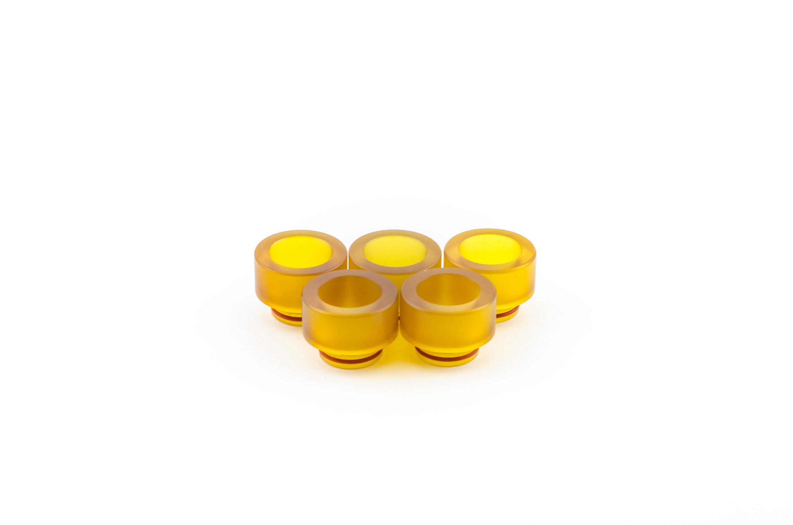
PEEK (Polyether Ether Ketone)
PEEK withstands continuous use up to 250 °C and resists aggressive chemicals like jet fuels, sterilization agents, and automotive fluids—making it ideal for aerospace brackets, medical implants, and under-the-hood components. Its high melt temperature and low flowability create risks of voids and warping, especially in thick or abrupt geometries. Managing uniform cooling and internal stresses is essential for dimensional accuracy.
Design Tips for PEEK:
- Maintain a uniform wall thickness of at least 2 mm to reduce void formation and warping.
- Use corner radii of 0.5 mm or greater to minimize stress concentrations.
- Avoid sharp transitions and sudden changes in wall thickness to promote consistent flow and cooling.
- Design parts with symmetrical geometries to ensure even shrinkage and dimensional stability.
PAI (Polyamide-imide)
Polyamide-imide excels in environments requiring resistance to extreme heat, chemicals, and mechanical loads, making it suitable for bearing cages, seals, and electrical insulators. Its molding is complicated by low flowability and significant internal stress buildup, which can cause incomplete filling and cracking. It can withstand continuous use temperatures above 250 °C (typically HDT >270 °C).
Proper gate design and wall thickness control are vital to overcoming these challenges. Furthermore, sharp corners and asymmetrical geometries can exacerbate stress concentrations and deformation after molding.
Design Tips for PAI:
- Limit wall thickness to between 2 and 3 mm to control internal stresses.
- Employ wide gates (≥1 mm) positioned near thicker features to facilitate better material flow and complete filling.
- Incorporate corner radii of at least 1 mm to reduce the risk of cracks.
- Maintain symmetrical part designs and avoid sharp transitions to prevent warpage.
- Reinforce thin sections with ribs when close to inserts.
PEI (Ultem® – Polyetherimide)
PEI offers a high UL 94 V-0 flame retardancy rating and outstanding dimensional stability, even in humid environments. With a melt temperature of approximately 340 °C, it is often chosen for high-temperature electrical connectors, aerospace sensor housings, and medical device enclosures. Due to its hygroscopic nature, poor drying can result in splay, bubbles, or internal stress.
Thin-walled designs benefit from uniform wall thickness and features like flow leaders to ensure consistent filling. Designers should also allow for slight dimensional expansion in assemblies to accommodate long-term moisture absorption.

Design Tips for PEI:
- Design uniform wall thicknesses ranging from 1.5 to 3 mm to avoid short shots and surface burns.
- Use flow leaders to guide material into ribs and deep cavities effectively.
- Apply fillets of 0.5 mm or more at corners to reduce stresses.
- Include 0.1 to 0.2 mm clearance in tight fits to accommodate moisture absorption.
- Position gates near thick or cored sections to ensure even filling without overheating.
- Avoid thin isolated features and sharp corners that could cause stress concentration.

LCP (Liquid Crystal Polymer)
LCPs offer exceptional flow characteristics and very low warpage, which make them ideal for ultra-thin and intricate parts such as microelectronic connectors and precision electrical components. Their unique molecular alignment enables precise molding even with wall thicknesses below 1 mm. However, rapid solidification at the flow front can lead to defects like short shots and weld lines if gating and flow paths are not optimized. LCP grades typically offer heat deflection temperatures in the range of 230–240 °C.
Design Tips for LCP:
- Maintain uniform wall thickness under 1 mm to ensure consistent filling.
- Keep flow lengths shorter than 150 mm to avoid incomplete fills.
- Use multiple gates positioned near the thickest zones to minimize weld lines.
- Design rounded transitions to promote smooth flow and packing.
- Avoid long, unbalanced cavities to reduce internal stress buildup.
PSU (Polysulfone)
PSU is prized for its transparency, dimensional stability, and heat resistance up to approximately 174 °C (HDT), making it suitable for medical devices and components exposed to hot water and steam. It is sensitive to moisture and prone to warpage if not carefully designed.
Thick walls increase internal stresses and can distort optical clarity, while sharp corners and abrupt thickness changes worsen these effects.
Design Tips for PSU:
- Limit wall thickness to below 3.5 mm to reduce warpage and stress.
- Use corner radii of at least 0.75 mm to lower stress concentration.
- Avoid sharp geometric transitions to improve flow and surface finish.
- Design thin, well-vented ribs to prevent splay and trapped air.
- Optimize parting lines and venting to preserve optical quality.
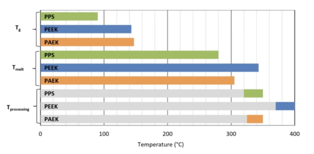
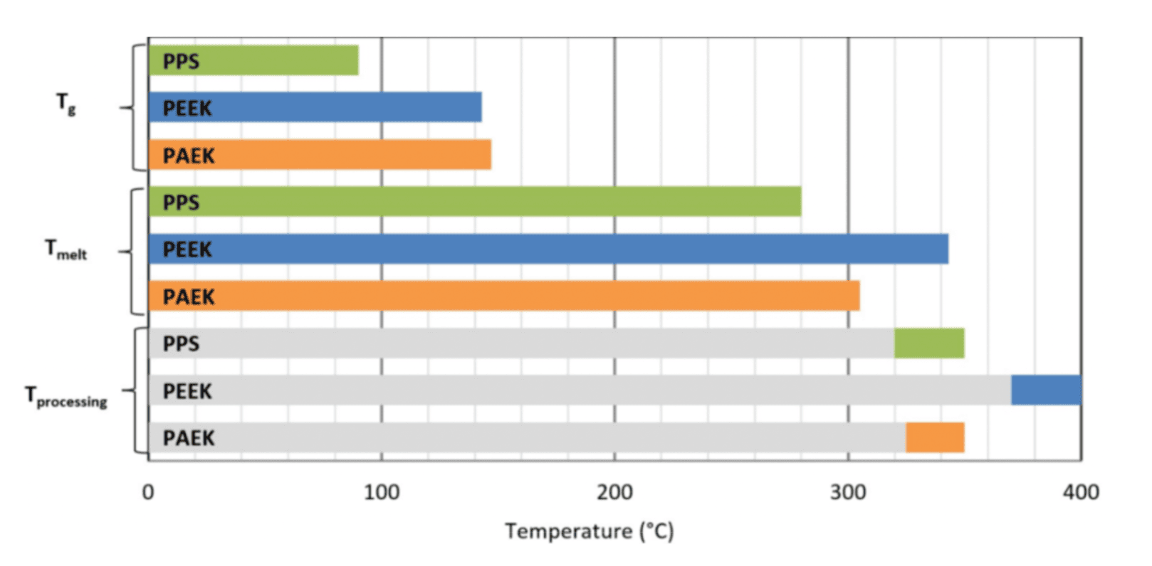
PPS (Polyphenylene Sulfide)
PPS is a chemically resistant and flame-retardant thermoplastic known for dimensional stability. Its rapid crystallization during molding requires careful control of cooling rates to avoid localized shrinkage differences and warpage. It maintains strength and shape up to approximately 200–220 °C.
Thick sections can lead to uneven stresses, so maintaining wall thickness under 4 mm is key. Symmetry in design and gradual transitions between features help minimize distortion. Reinforcing ribs provide strength without adding problematic bulk.
Design Tips for PPS:
- Keep wall thickness under 4 mm to prevent shrinkage variation.
- Use symmetrical part designs to maintain uniform cooling.
- Replace thick walls with ribs to increase strength without warpage.
- Smooth transitions between features reduce stress concentration and flow issues.
- Avoid sharp corners that can disrupt material flow.
PA (Polyamide – Nylon – High Performance Grades)
High-performance nylons such as PA6T, PA9T, and glass-filled PA66 deliver superior mechanical strength, thermal resistance, and chemical durability. They are widely used in automotive engine parts, sensor housings, and connector shells within electronics. These grades typically remain dimensionally stable up to 120–150 °C, depending on reinforcement and formulation.
Compared to standard PA6 or PA66, these advanced grades maintain stability above 120 °C and offer improved dimensional control. However, moisture absorption and uneven shrinkage remain key concerns.
Design Tips for High-Performance PA (PA6T, PA9T, Glass-Filled PA66):
- Use uniform wall thickness between 2 and 3 mm to balance mechanical strength and minimize internal stresses.
- Apply larger corner radii of ≥ 0.75 mm to effectively reduce stress concentrations and improve flow in reinforced materials.
- Incorporate well-vented, slender ribs with a thickness ratio of about 0.5 to 0.6 of the nominal wall to strengthen parts without creating sink marks or warpage.
- Position gates to ensure balanced filling and optimized fiber orientation, especially critical for glass-filled grades to avoid warpage and anisotropic shrinkage.
- Design gradual thickness transitions to reduce differential shrinkage and internal stresses common in semi-crystalline reinforced nylons.
- Avoid abrupt geometric changes and isolated thin sections to prevent weak spots and incomplete fills.
- Consider draft angles of 1–2° or higher on sidewalls for easier ejection of high-performance nylon parts.
POM (Polyoxymethylene – Acetal)

Although not traditionally classified alongside ultra-high-performance plastics like PEEK or PAI, POM stands out for its exceptional dimensional stability, machinability, and low friction characteristics. POM is ideal for precision mechanical assemblies, gears, and fluid system components requiring tight tolerances and wear resistance. It can operate reliably in environments up to 100–120 °C.
Though it has lower thermal and chemical resistance than ultra-high-performance plastics, its ease of flow and low moisture uptake allow for consistent molding without major adjustments.
Design Tips for POM:
- Keep wall thickness uniform and under 3 mm to avoid sink marks.
- Use smooth, gradual transitions between ribs, bosses, and flat surfaces to reduce internal stress.
- Apply corner radii of at least 0.5 mm for improved flow and reduced stress.
- Design balanced flow paths to minimize warpage and ensure consistent part quality.
- Avoid abrupt thickness changes that could cause flow hesitation or shrinkage variation.
General Design Tips for Reliable Molding of High-Performance Plastics
High-performance plastics have narrow processing windows that directly affect part geometry and tool design. Designers who apply these tips early in CAD reduce mold rework, warpage, and performance inconsistencies across part runs.
Minimize Internal Stress & Warpage
- Use uniform wall thickness (±10%) across the part; avoid abrupt transitions.
- Include generous internal corner radii (≥0.5 mm) to reduce shear buildup.
- Balance wall distribution with symmetrical features and coring.
Enable Complete and Controlled Fill
- Choose gate types based on material: fan/tab gates for fiber-filled, pin gates for LCP.
- Position gates near thicker cross-sections and align with primary flow directions.
- Reduce flow length for low-viscosity or fast-freezing materials (e.g., LCP, PPS).
Control Shrinkage & Dimensional Drift
- Account for shrink ranges per material: PA (0.7–1.5%), POM (up to 2.0%).
- Design ribs instead of thick walls for stiffness and mass control.
- Add expansion tolerance for hygroscopic plastics (e.g., PA, PEI).
Ensure Surface & Assembly Compatibility
- Avoid high-gloss finishes for abrasive materials (PEEK, PAI).
- Use moderate textures (VDI 27–33) for durability and consistent release.
Best Practices and Process Adjustments
While the following settings are basic for all high-performance polymers, they become even more critical for low-flow grades such as PAI and PPS.
- Gate placement should be close to core features (within 50 mm) for stiff or filled materials.
- Strategic venting (15–30 µm) at last-fill points eliminates voids and burn marks.
- Balance insert locations to reduce asymmetric shrinkage, especially for PEEK and PAI.
- When designing two-shot or overmolding processes (e.g., soft elastomer over rigid PEEK), verify thermal expansion compatibility and optimize bond interfaces (textured inserts or interlocking features).
- Anneal PAI and PEEK parts at 200°C for 2 hours after molding to relieve internal stresses.
Designing with Confidence for High-Performance Plastics
Every high-performance part starts with the right design mindset, clear material limits, thoughtful geometry, and manufacturing-aware decisions. High-performance plastics reward precision—and penalize oversight.
Have you experienced any challenges when working with high performance plastics? Share your toughest molding challenges or best design solutions in the Xometry Pro Community. Collaborate with peers and enhance your expertise in injection molding high-performance plastics.


Comment(0)