

 Europe
  Türkiye
  United Kingdom
  Global








 Login with my Xometry account
 ISO 2768 General Tolerances Calculator
Instantly compute tolerance bands, verify measured parts, and assess DfM cost impact.
Lengths, diameters, steps - the most common drawing dimension.
Standard CNC milling & turning. Best balance of precision and manufacturing cost. The correct default for the vast majority of machined features.
Enter nominal drawing dimension in mm.
Compare an actual measured dimension against the computed limits.
Measured-value check isn't available for angular dimensions - degree tolerances can't be compared against millimetre limits.
Controls straightness, flatness, and circular run-out on features with no explicit form tolerance. Independent from the f/m/c/v class above - a full title-block callout combines both, e.g. ISO 2768-mK.
This value is outside the defined ISO 2768 range for this dimension type. No tolerance applies.
±0.30 mm
mm - nominal 50 mm, class m
50.300
49.700
Tolerance Zone Preview
| Nominal Range (mm) | f - Fine | m - Medium | c - Coarse | v - V. Coarse |
|---|---|---|---|---|
| 0.5 – 3 | ±0.05 | ±0.1 | ±0.2 | — |
| >3 – 6 | ±0.05 | ±0.1 | ±0.3 | ±0.5 |
| >6 – 30 | ±0.1 | ±0.2 | ±0.5 | ±1 |
| >30 – 120 | ±0.15 | ±0.3 | ±0.8 | ±1.5 |
| >120 – 400 | ±0.2 | ±0.5 | ±1.2 | ±2.5 |
| >400 – 1000 | ±0.3 | ±0.8 | ±2 | ±4 |
| >1000 – 2000 | ±0.5 | ±1.2 | ±3 | ±6 |
| >2000 – 4000 | — | ±2 | ±4 | ±8 |
What is ISO 2768 and When Do You Need It?
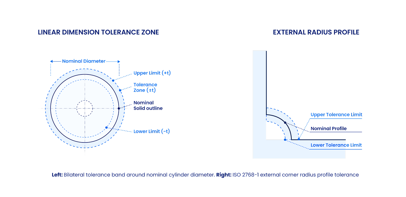
ISO 2768 defines general tolerances for linear dimensions, external radii, chamfer heights, and angular dimensions on engineering drawings — specifically for features where no individual tolerance is explicitly stated. It simplifies drawings by letting a single title-block notation (e.g. ISO 2768-m cover every non-critical dimension, eliminating the need to annotate every feature individually.

Part 1: Dimensions
Controls linear lengths, diameters, radii, and angles. Four classes: f, m, c, v. No datum references required.

Part 2: Geometry
Controls form tolerances — flatness, straightness, circularity, run-out. Three classes: H, K, L. Separate from Part 1.

When to Override
Critical interfaces — bearing seats, press fits, sealing surfaces — must have explicit tolerances stated directly on the drawing face.
Frequently Asked Questions
What is the difference between ISO 2768-1 and ISO 2768-2?

ISO 2768-1 covers general tolerances for linear and angular dimensions on features where no explicit tolerance is shown: lengths, radii, chamfer heights, and angles. It defines four accuracy classes (f, m, c, v) and requires no datum references.
ISO 2768-2 is a separate standard governing geometric form tolerances — straightness, flatness, circularity, cylindricity, and run-out — using three classes (H, K, L). Both are commonly referenced together in a drawing title block, for example ISO 2768-mK, to provide full coverage for both dimensions and form. The two parts control completely different error types and are independently specified.
| Standard | Controls | Classes | Datum Required |
|---|---|---|---|
| ISO 2768-1 | Linear dims, radii, chamfers, angles | f, m, c, v | No |
| ISO 2768-2 | Flatness, straightness, circularity, run-out | H, K, L | Yes (for position) |
Which tolerance class should I specify for a standard CNC machined feature?
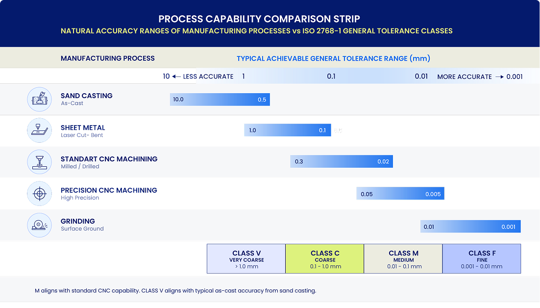
Class m (Medium) is the correct default for the vast majority of CNC milling and turning features. It reflects the natural accuracy envelope of modern 3-axis machine tools under standard production conditions, without requiring special fixturing, temperature control, or inspection routines.
| Class | Name | Suitable Process | Cost vs. Class m | Default for |
|---|---|---|---|---|
| f | Fine | Precision CNC | +30–60% | Critical mating surfaces only |
| m | Medium | Standard CNC milling/turning | Baseline | General machined features |
| c | Coarse | Sheet metal, basic fabrication | -20–40% | Non-critical holes, flanges, bends |
| v | Very Coarse | Sand casting, forging, flame cut | -40–60% | Cast and forged structural profiles |
Specifying class f for non-critical features adds cycle time, tooling qualification overhead, and inspection cost without functional benefit. For cost-sensitive parts, cross-reference tolerance selection against the DfM ebook on Xometry Pro before finalising the drawing.
Why do angular tolerances tighten as the leg length decreases?
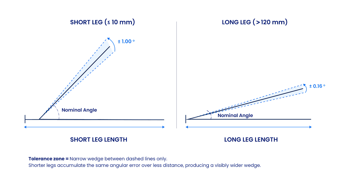
This follows from basic trigonometry. The linear positional error at the end of an angle leg equals the leg length multiplied by the sine of the angular deviation. A short leg amplifies angular error into a large linear consequence at the measured surface. A long leg geometrically dilutes the same angular error.
ISO 2768-1 compensates by assigning tighter degree tolerances to shorter legs, keeping the maximum linear consequence of any angular variation within a consistent practical band.
| Shortest Leg (mm) | Class m Angular Tolerance | Equivalent Linear Error at Leg End (class m) |
|---|---|---|
| Up to 10 | ±1° | ±0.17 mm at 10 mm |
| >10 to 50 | ±0°30′ | ±0.44 mm at 50 mm |
| >50 to 120 | ±0°20′ | ±0.70 mm at 120 mm |
| >120 to 400 | ±0°10′ | ±1.16 mm at 400 mm |
| >400 | ±0°5′ | Same order at large scale |
This design produces roughly consistent linear consequence regardless of leg length, which is the practical intent of the standard.
What should I do when ISO 2768 tolerances are too loose for a critical feature?
Declare an explicit tolerance directly on the drawing for that specific feature. ISO 2768 is a catch-all baseline — it is overridden entirely by any feature-level annotation. Three main tools apply depending on the requirement:
| Requirement | Tolerancing Approach | Example Notation |
|---|---|---|
| Precision bore/shaft fit (clearance, transition, interference) | ISO 286 limits and fits | H7/g6, K7, p6 |
| Dimensional coordinate tolerance | Bilateral explicit | ±0.010 mm |
| Positional or form accuracy | GD&T with datum | ⌀0.02 (M) A B |
| Surface interface (seal groove, bearing seat) | ISO 286 + surface finish | N7, Ra 0.8 |
How does ISO 2768 relate to GD&T (Geometric Dimensioning and Tolerancing)?
ISO 2768-1 controls size and angular dimensions. GD&T (per ISO 1101 or ASME Y14.5) controls form, orientation, location, and run-out — the geometric relationship between features. They are complementary, not competing.
ISO 2768-2 provides a simplified substitute for GD&T form tolerances when the full datum reference framework of ISO 1101 is not warranted. Most industrial parts use a combination: ISO 2768-m(K) in the title block as the general baseline, with GD&T callouts added only on features where geometric accuracy is functionally critical.
The key rule: any explicit ISO 1101 / GD&T callout on a feature overrides the ISO 2768-2 general form tolerance for that feature, just as an explicit size tolerance overrides ISO 2768-1.
Can I use ISO 2768 tolerances to verify a part on the shop floor?
Yes. The QA Inspection mode in this calculator automates the check. Enter the nominal dimension, select the drawing class, enable QA mode, and enter the measured value. The tool returns PASS or FAIL with the deviation from the nearest limit.
Manual calculation procedure if checking without the tool:
- Identify nominal dimension and ISO 2768 class from the drawing title block
- Determine dimension type (linear, radius, angular)
- Read ± tolerance from the standard table for the correct nominal range
- Upper limit = nominal + tolerance, Lower limit = nominal – tolerance
- Part passes if measured value falls between the two limits
What is the difference between ISO 2768 and ISO 286?
Both are dimensional tolerancing standards but they apply at different levels of the same drawing and control different things.
| Property | ISO 2768-1 | ISO 286-1 |
|---|---|---|
| Applied via | Title block callout | Feature annotation (e.g., 25H7) |
| Controls | All unspecified dimensions | Specific bore/shaft fit precision |
| Tolerance type | Bilateral ±band | Unilateral upper + lower deviations |
| Datum required | No | No (size); Yes (when position GD&T added) |
| Overrides the other | Never — is the baseline | Yes, always overrides ISO 2768 on that feature |
| Typical use | General milled features | Bearing seats, press fits, sliding clearances |
Use ISO 2768 as the drawing baseline. Apply ISO 286 notation on any feature where fit precision directly affects assembly performance.
Ready to manufacture to these tolerances?
Upload your CAD file for an instant quote from Xometry's vetted manufacturing network across Europe.
