 Europe
  Türkiye

Selective Laser Sintering (SLS) is a powder-based 3D printing technology that enables the production of complex, high-strength parts without the need for support structures. This makes it a preferred choice for functional prototypes and end-use applications. SLS can achieve excellent mechanical properties, particularly when using materials like PA 12, PA 11, or reinforced composites (e.g. PA 12 glass-filled).
Compared to other 3D printing technologies like FDM, SLS offers superior design freedom, better surface quality, and isotropic mechanical properties. Additionally, because multiple parts can be nested within the build chamber, SLS is well-suited for batch production. However, designing for SLS requires careful consideration to avoid issues such as warping, trapped powder, or weak structures.
1. Maintain Proper Wall Thickness
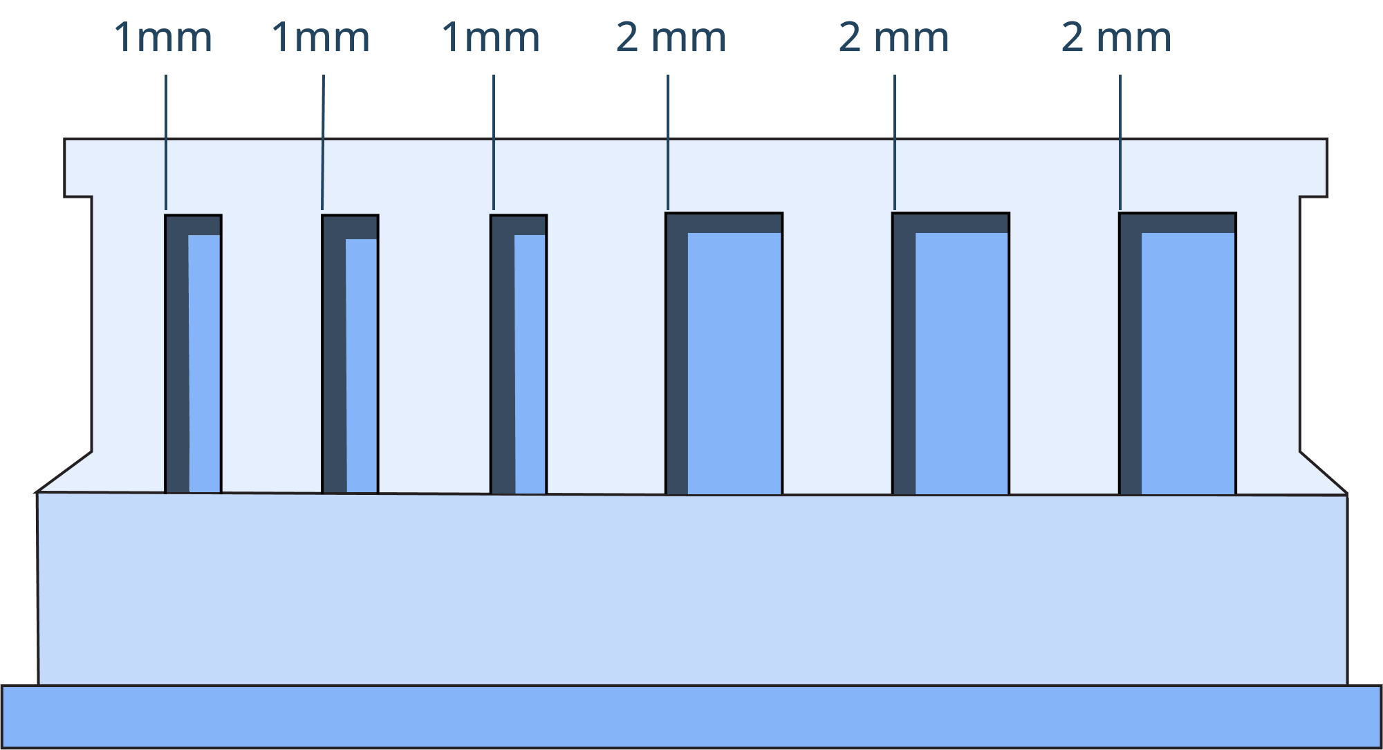
Wall thickness plays a crucial role in the structural integrity, accuracy, and manufacturability of SLS parts. If walls are too thin, they may warp, crack, or become brittle due to insufficient material support and the thermal stress of the sintering process.
Walls thinner than 0.5 mm are particularly problematic, as they tend to over-thicken due to the heat from the laser, leading to unintended dimensional inaccuracies. Thin sections can also be fragile during post-processing, such as bead blasting.
On the other hand, excessively thick walls can retain heat for too long, leading to internal stresses, warping, and shrinkage. This can result in parts with poor dimensional accuracy or surface defects. Thick sections may also increase material costs and extend cooling times, affecting overall production efficiency.
Rule of Thumb:
- Design walls at least 0.5 mm (PA 12) – 2.0 mm thick (), depending on the material.
- Walls as thin as 0.6 mm are possible if a support structure is provided, but for reliable and repeatable results, 1.5 mm is preferred.
- In most cases, walls do not need to exceed 5 mm, as thicker sections can lead to heat buildup and warping.
- Maintain consistent wall thickness to prevent warping.
- Add ribs or fillets for extra strength in thin areas.
2. Design for Effective Powder Removal
Since SLS prints without support structures, excess unsintered powder remains inside hollow parts, internal channels, and cavities. If not properly removed, this trapped powder can add unnecessary weight, affect mechanical performance, and complicate post-processing. Residual powder inside a part can also interfere with moving assemblies or functional features, making it essential to design for efficient powder evacuation.
To reduce weight and material use, parts can be designed hollow rather than solid. However, for these hollow structures, escape holes must be included to allow the removal of residual powder. Without sufficient openings, powder may become compacted inside, making it difficult—if not impossible—to clear out completely.

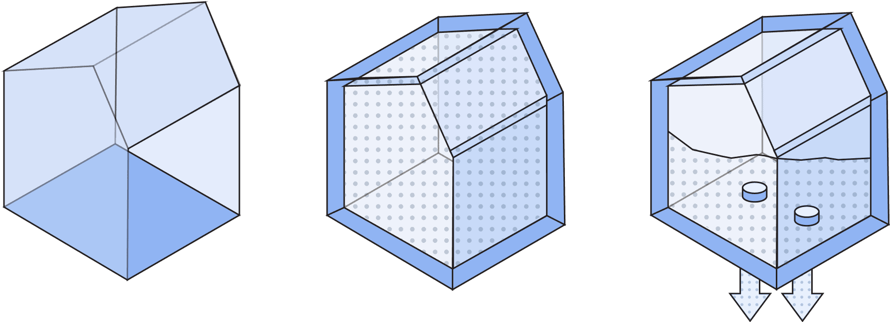
Additionally, sufficiently large escape holes enable post-processing techniques like media tumbling to smooth the interior surfaces of hollow parts.
Rule of Thumb:
- Minimum escape hole diameter: 3.5 mm. The larger, the better!
- Place multiple escape holes near edges or opposite sides for effective powder removal.
- Ensure smooth internal passages to prevent powder buildup.
3. Optimize Hole and Channel Geometry
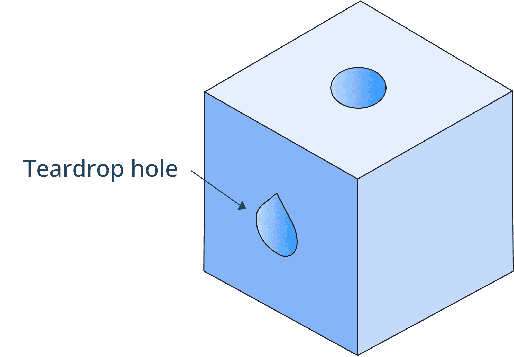
SLS enables the creation of complex internal channels and holes, but improper design can lead to shrinkage, distortion, or blockages. Round holes may shrink during sintering, and poorly oriented channels can trap powder or lose accuracy.
The shrinkage rate for SLS is as high as 3% to 4%, which is comparatively higher than the alternatives. To compensate for this, it is recommended to design holes to standard drill sizes so they can be mechanically reamed or opened if needed for better accuracy.
If you need to integrate a connection point for components within a channel (e.g., an air intake), design an aerodynamic support structure in the shape of streamlined droplets. This minimizes airflow obstruction while ensuring sufficient strength for secure attachment.

Rule of Thumb:
- Minimum hole diameter: 1.5 mm.
- Use tear-drop or diamond-shaped holes instead of circular ones.
- Orient holes vertically where possible for better accuracy.
4. Ensure Proper Clearance for Mating Parts
Moving or interlocking parts require precise spacing to function correctly. If clearances are too tight, parts may fuse together during sintering, making them non-functional.
Conversely, too much clearance can result in loose assemblies that don’t fit properly, reducing mechanical stability.
One of the advantages of SLS is that it can print mating and moving parts in a single build, eliminating the need for separate prints and manual assembly. This allows for the production of fully functional assemblies in one manufacturing cycle. However, to ensure that printed assemblies do not become one solid part, proper clearance is essential to allow the thorough removal of excess powder.

Rule of Thumb:
- Clearance for mating parts: 0.7 mm minimum.
- Press-fit features: 0.5 mm clearance for tight fits.
- Articulated or linked parts: 0.6 mm gap to avoid sticking.
5. Avoid Large Overhangs and Unsupported Spans
While SLS does not require support structures, excessively long overhangs or unsupported spans may sag, deform, or develop rough finishes due to the effects of gravity and residual heat.
To improve print quality and maintain dimensional accuracy, designs should prioritize self-supporting geometries with gradual transitions rather than abrupt overhangs. Features such as arches, domes, or angled surfaces (typically 45° or less from the build platform) can help distribute stress more effectively and reduce the risk of sagging.

Rule of Thumb:
- Keep overhang angles below 45° for best results.
- Design self-supporting geometries like chamfers and fillets. Use angles of 30° or less and add fillets or chamfers on corners.
- Limit unsupported bridge spans to 2 mm to maintain structural soundness and surface quality.
6. Use the Right Feature Sizes for Small Details
Fine details like embossed text, logos, and surface textures may become blurred or unreadable if they are too small. Ensuring proper feature size improves visibility and maintains sharp details after printing.
During the SLS process, details can be engraved or embossed directly onto the part with a minimum depth or height of 1 mm. This depth is particularly important for post-processing, as engraving or embossing less than 1 mm may wear off during media tumbling or other finishing treatments. Text can also be printed directly onto SLS parts, but for optimal readability, letters should be at least 2 mm in height.
Additionally, adding a small draft angle to text can further enhance durability, ensuring that delicate features—such as the dot on a lowercase “i”—withstand post-processing and handling.
Rule of Thumb:
- Embossed text height (font size) or engraved depth: 1 mm.
- Minimum font size for readability: 2 mm.
- Use Sans-serif fonts for better readability.
7. Reinforce Long, Thin Features
Slender, unsupported features like pins, thin walls, and delicate details can break easily or warp under thermal stress. The combination of high printing temperatures and cooling shrinkage can cause these features to weaken, bend, or become fragile, especially during post-processing or handling. Reinforcing these elements improves durability and structural stability.
Rule of Thumb:
- Minimum pin diameter: 0.8 mm (preferably 1 mm or more).
- Add supports like ribs or gussets to reinforce thin features and connect them to the main body.
- Avoid tall, narrow structures without additional bracing.
- Use gradual transitions rather than abrupt changes in cross-section.
- Orient parts optimally in the build chamber, like printing long, thin features parallel to the build platform rather than standing upright.
8. Consider Shrinkage and Dimensional Accuracy
SLS parts may experience minor shrinkage during cooling, which can impact precision and tolerances. This is due to the thermal nature of the sintering process, where material contracts as it cools. Designing with expected dimensional changes in mind helps prevent inaccuracies and ensures a better final fit, especially for parts that require assembly.
If you’re printing parts yourself, keep in mind that achievable dimensional accuracy depends on the printer and part size. SLS is capable of high precision, typically up to ±0.3% of feature dimensions, with a minimum of ±0.3 mm. However, tolerances should be limited to areas where they are truly necessary, such as mating surfaces or functional interfaces. Applying excessive tolerances throughout the design increases printing effort and costs without adding practical benefits.
If you’re having your parts produced with Xometry, shrinkage and dimensional accuracy are handled by our manufacturing partners as part of the printing process.
Rule of Thumb:
- Dimensional tolerance: ±0.3 mm
- Account for expected shrinkage in CAD models (typically 3–4%)
- Avoid sharp edges to reduce thermal stress and ensure stronger parts.
SLS Technology Specifications Reference Guide
The table below provides a quick summary of SLS 3D design specifications at Xometry for various part features. These are all vital to consider during the design phase for high-quality prints.
| Specifications | Details |
| Maximum build volume | 700 x 380 x 580 mm. Recommended: 320 x 320 x 580 mm |
| Minimum feature thickness | 0.50 mm |
| Suggested minimum wall thickness | 0.50 mm (supported), 0.60 mm (unsupported) |
| Layer Thickness | 0.10 – 1.50 mm. ~0.1 mm and for water-tight parts 1.5 mm, when wall thickness is higher |
| General tolerance | ±0.3% (± 0.3 mm) |
Additionally, sufficiently large escape holes enable post-processing techniques like media tumbling to smooth the interior surfaces of hollow parts.
Get Your Designed Parts 3D-Printed at Xometry
SLS is an invaluable technology for creating complex and high-quality parts. By understanding and predicting the potential challenges during the design, processing, and post-processing phases, you can significantly enhance the success of your SLS designs.
When designing for manufacturability, consider factors such as wall thickness and other intricate details. Address all potential causes of defects at the design phase to avoid warping, cracking, and weak points on the printed parts. Additionally, optimize your designs to eliminate material wastage and choose the most appropriate material for the application. This ensures the SLS printed parts are strong, durable, and functional.
If you’re ready to take your SLS designs to the next level, explore Xometry’s expert SLS 3D printing services and start your 3D printing project today!

Comment(0)