 Europe
  Türkiye


What is CNC Machining Surface Roughness
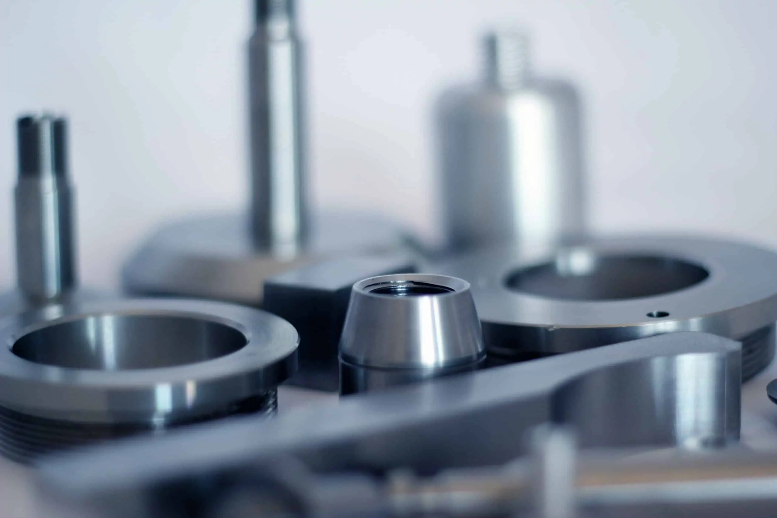
CNC machining surface roughness measures the imperfections or texture on the surface of a machined part. Think of it as the bumps and grooves you’d see under a microscope — it’s all about the tiny details you can’t see with the naked eye. Even after processes such as blasting, polishing, or other applied surface finishes, some degree of roughness may remain. These surface irregularities are an inherent result of CNC machining, a subtractive manufacturing process in which material is removed from workpieces using cutting tools. The cuts left by these tools form irregularities, often invisible to the naked eye.
Surface roughness is critical in determining the performance of CNC machined parts, as it directly influences key parameters such as the friction coefficient, noise level, wear and tear, heat generation, and adhesiveness. If you’ve ever wondered why some components fit together perfectly while others don’t — it’s all down to tolerance and roughness. These factors are vital in selecting the most appropriate surface roughness level for specific applications, making it an essential consideration for engineers and manufacturers.
Surface roughness is not always undesirable. It’s not all about making things as smooth as possible. In some CNC machined parts, specific roughness levels are required as part of product manufacturing guidelines. For example, certain machined parts may rely on rougher surfaces to enhance adhesion or performance under specific conditions. Manufacturers may need to refine surface irregularities to meet the intended purpose of the machined part, highlighting the importance of carefully evaluating and specifying surface roughness levels in the production process.
Common CNC Machining Surface Roughness Levels
Let’s break this down into real-world applications. The table below outlines common CNC machining surface roughness levels, their recommended applications, and the impact on machining time and cost.
| Surface Roughness Type | Recommended Applications | CNC Machining Time | Price Impact |
| 3.2 μm Ra | Suitable for parts subjected to stress, loads, and vibrations. Common in brackets, automotive engine covers, general tooling fixtures, and machine chassis. | Less time is required since there are no additional manufacturing processes. | Baseline finish for parts; no extra costs |
| 1.6 μm Ra | Ideal for slow-moving surfaces with light loads, such as hydraulic piston rods, slow-speed gearboxes, precision fasteners, and electronic housing. | It requires controlled conditions, which add to production time. | Increases costs by ±2.5%. More complex parts will have higher costs. |
| 0.8 μm Ra | Best for high-stress applications or surfaces with occasional motion, such as hydraulic valve components and electronic housings. | Produced under highly controlled conditions, increasing production time. | Adds ±5% to production costs. More complex parts will have higher costs. |
| 0.4 μm Ra | Recommended for high-speed or high-stress components such as pneumatic cylinder rods, optical components, and precision injection moulds. | Requires polishing and advanced processes, taking the most time. | Adds ±11-15% to production costs. More complex parts will have higher costs. |

How Post-Processing Operations Impact the Surface Roughness of Machined Parts
Post-processing techniques, such as bead blasting, electropolishing, anodising, plating, and powder coating, can affect the surface roughness and overall dimensions of the component. The post-processing technique also affects the surface finish of the manufactured component. For a matte or grainy finish, bead blasting is preferred, and a glossy, smooth finish can be achieved through vapour smoothing or electropolishing. Choosing the right technique ensures components meet industry standards and performance requirements.
How is Surface Roughness Measured?
Every CNC machined part leaving the production line has a specific Ra value and other indicators assigned to it. These are measured with advanced methods that leave no room for error. Some of the most commonly used techniques include the following:
- Contact Profilometers: Uses a diamond stylus that slides on the surface of the machined part, and its deflections are recorded.
- Non-Contact Profilometers: Uses different techniques to measure surface roughness without physical contact with the machined component. Common techniques include digital holography, laser triangulation, confocal microscopy, and optical profilometry.
- Atomic Force Microscopy (AFM): A highly advanced technology that is ideal for measuring surface roughness of smooth surfaces. It employs probes to accurately scan the surfaces of machined parts and provides nanometer-level accuracy.
- 3D Scanning: Creates surface topography maps, and is one of the most advanced surface roughness measuring techniques.

CNC Machining Surface Roughness Indicators
Roughness indicators help determine the suitability of parts for specific applications based on their functional and aesthetic requirements. Below is an overview of key surface roughness indicators.
Ra (Average Roughness)
Ra is calculated as the arithmetic mean of the absolute deviations of the surface profile from the mean line over the evaluation length. It essentially averages the height differences between peaks and valleys, ignoring their sign, to provide a single roughness value.


- Rp (Maximum Profile Peak Height): The height of the tallest peak from the mean line.
- Rv (Maximum Profile Valley Depth): The depth of the deepest valley from the mean line.
- L: Evaluation length
Significance: Ra is the most widely used parameter as it provides a general indication of overall surface texture without being overly influenced by extreme peaks or valleys
Applications: Suitable for general-purpose parts where moderate smoothness is acceptable.
Rz (Average Maximum Height)
Rz is the average of the maximum peak-to-valley heights within five equal sampling lengths:


- From the highest peak to the lowest valley
- From the second highest peak to the second lowest valley
- etc. until the fifth’s biggest distance
Significance: Offers a more detailed representation of surface texture by focusing on extreme variations.
Applications: Critical for sealing surfaces or applications where peaks and valleys impact performance.
Rt (Total Roughness)
Rt is the total vertical distance between the highest peak and lowest valley within the evaluation length.
Significance: Useful for overall quality control to ensure no extreme deviations exist
RMS (Root Mean Square Roughness)
RMS is the root mean square average of height deviations from the mean line.
Significance: Gives more weight to larger deviations, making it ideal for precision engineering and optical applications.
Comparison of Indicator Applications
| Indicator | Usage Frequency | Focus | Sensitivity to Outliers | Use Case |
| Ra | Most commonly used worldwide | Average deviation of surface heights from the mean line | Low | General-purpose applications; widely used for machining, casting, and grinding processes. |
| Rz | Second most commonly used after Ra | Average of maximum peak-to-valley heights across sampling lengths | Moderate | Critical interfaces like sealing surfaces, load-bearing parts, and wear-prone components. |
| RMS | Less common but used in precision applications | Root mean square of height deviations from the mean line | Moderate to High | Precision engineering, optics, and applications where larger deviations must be emphasized. |
| Rt | Least commonly used | Total height difference between the highest peak and the lowest valley over the evaluation length | High | Detecting extreme surface defects; useful for quality control in critical applications. |
Since Ra and Rz are the most commonly used indicators, the following sections of this article review these measurement systems.
N – Roughness Grade Numbers (DIN ISO 1302)
Speaking about Ra it is important to mention DIN ISO 1302 standard and N (Roughness Grade Numbers). It is a standardized system used to classify surface roughness in engineering and manufacturing. These grades, ranging from N1 (finest) to N12 (roughest), correspond to specific maximum Ra values and are commonly used on technical drawings to specify surface finish requirements.
Connection between Ra, Rz and N
- Ra – N: As mentioned above, N1-N12 values directly represent specific Ra values.
- Ra – Rz: not directly convertible since they measure different surface characteristics. However:
- Statistical analysis allows us to define a possible range of Rz values for each Ra.
- For any given Ra, there is a range of potential Rz values, and vice versa.
- As surface roughness increases, the range of Rz values becomes less precise.
The chart below illustrates this:
- A surface with an Ra of 3.2 µm can have an Rz roughness between 11.5 and 34.7 µm.
- A surface with an Ra of 50 µm may have an Rz roughness between 156.2 and 272.6 µm.


Surface Roughness Grades
The table below outlines N1–N12 values, their corresponding Ra values, and the statistical range of Rz values for each Ra. For added convenience, you can also use our online surface roughness conversion tool.
| Roughness Grade | Ra (µm) Metric Units |
Metrics Rz (µm) Metric Units |
Ra (µin) Imperial Units |
Rz(µin) Imperial Units |
| N12 | 50 | 156.245-272.644 | 2000 | 6249.8-10905.7 |
| N11 | 25 | 156.2-272.6 | 1000 | 3235.1-6484.6 |
| N10 | 12.5 | 80.9-162.1 | 500 | 1674.6-3855.8 |
| N9 | 8.3 | 21.8-57.7 | 250 | 873.4-2306.4 |
| N8 | 3.2 | 11.5-34.7 | 125 | 458.9-1387.7 |
| N7 | 1.6 | 5.9-20.6 | 63 | 237.6-825.1 |
| N6 | 0.8 | 3.1-12.3 | 32 | 123.0-490.6 |
| N5 | 0.4 | 1.6-7.3 | 16 | 63.7-291.7 |
| N4 | 0.2 | 0.8-4.3 | 8 | 32.9-173.5 |
| N3 | 0.1 | 0.4-2.6 | 4 | 17.1-103.1 |
| N2 | 0.05 | 0.2-1.5 | 2 | 8.8-61.3 |
| N1 | 0.025 | 0.1-0.9 | 1 | 4.6-36.5 |
Roughness Grades Achievable and not Achievable with CNC Machining
The table below provides an overview of the manufacturing methods used to achieve each roughness grade, with the most common surfaces achievable through CNC machining highlighted in blue.
How To Choose the Most Suitable CNC Machining Surface Roughness
Selecting the most appropriate CNC machining surface roughness is crucial for ensuring optimal performance, cost-efficiency, and suitability for the intended application. Several factors must be carefully evaluated to make the best choice, ranging from the component’s functionality to its material properties and design complexity. Below are the key considerations to guide your decision-making process:
- Functionality and Purpose
- Consider the specific function of the CNC machined parts, as surface roughness directly impacts performance.
- For components like pneumatic cylinder rods and optical parts, smooth surfaces are essential (e.g., 0.4 μm Ra).
- Refer to the comparison chart for recommended Ra values tailored to various applications.
- Cost and Lead Time
- Smoother surfaces require longer machining times and increase production costs.
- For non-critical components, a surface roughness of 3.2 μm Ra can save time and reduce expenses.
- Aesthetics
- Consumer-facing products benefit from smooth, glossy finishes that convey higher quality.
- Hidden parts, such as suspension system components, may not require aesthetic finishes, reducing production demands.
- Material Properties
- The achievable surface roughness depends on the material.
- Aluminium can achieve Ra values between 0.1 µm and 1 µm, while materials like steel may have higher limits.
- Part Geometry
- Complex designs with intricate geometries require more time and advanced equipment to achieve lower Ra values.
- For tight budgets and deadlines, consider rougher surface finishes to balance cost and feasibility.
Ordering CNC Machined Parts
Understanding surface roughness is key to ensuring your components perform as needed. Whether you’re working on precision gears for aerospace or durable engine covers for vehicles, the right roughness level directly impacts quality and functionality. With this knowledge, you can make informed decisions and optimize your next project.
Xometry offers CNC machining solutions tailored to your specific requirements. Whether you need smooth finishes or complex geometries, our engineers are ready to assist. Upload your CAD files and get an instant quote.
Ra – Rz – N Surface Roughness Conversion Tool
Do you have a Ra, Rz or N roughness value and need to get its equivalent in other units? Use our free tool for that.


Comment(0)