 Europe
  Türkiye
  United Kingdom
  Global


 0
0

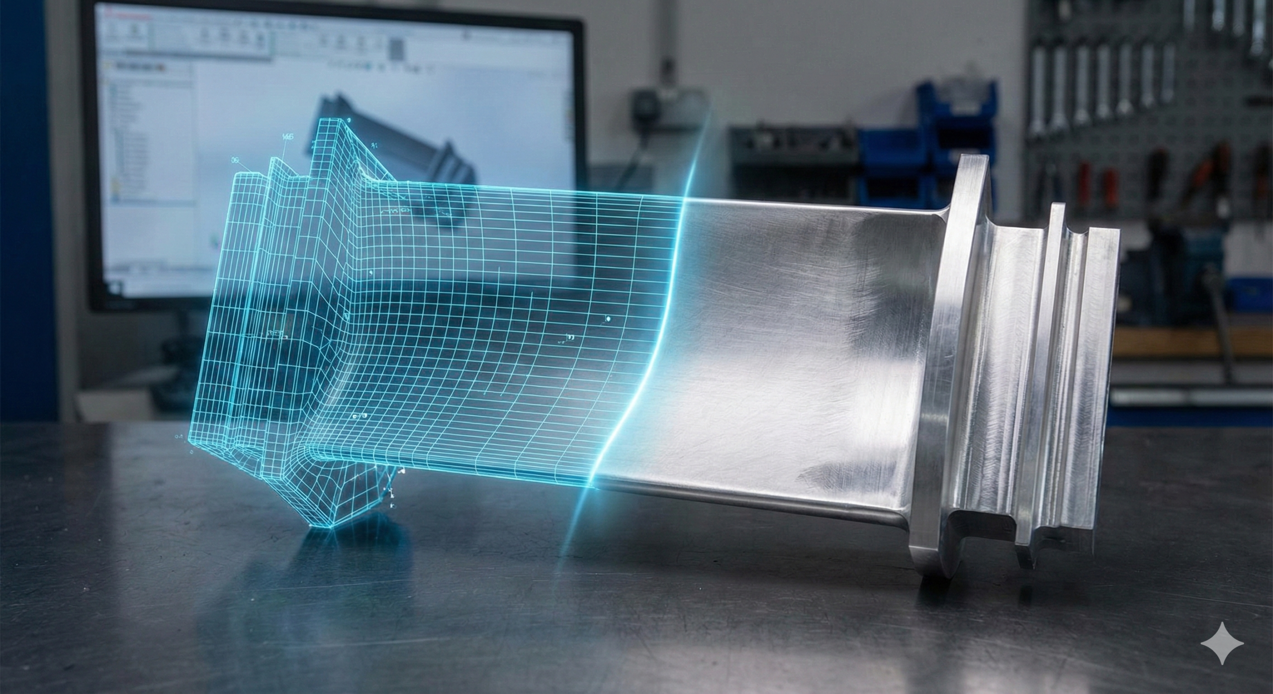
By applying best practices in design, mould engineering, and process control, these defects are largely predictable and avoidable. This article identifies common injection moulding defects, examines their underlying reasons, and offers practical solutions to help you achieve consistently high-quality moulded parts.
Quick-Reference Defect Comparison Table
The table below summarises the various injection moulding defect types and highlights their causes and possible design solution or prevention methods. More details are provided in the next section.
| Injection Moulding Defect | Causes | Quick Design Tips |
| Flash: Thin plastic seepage along parting lines or ejectors | Overly tight radii near parting lines, inconsistent wall thickness, parting line in high-stress area, excess pressure, sharp corners, tool wear | • Place parting lines on low-visibility surfaces
• Avoid sharp corners near mold splits • Maintain even wall thickness |
| Short Shots: Incomplete fill; missing or thin sections | Thin walls, sharp transitions, complex flow paths, low pressure | • Keep walls > 0.8 mm
• Avoid sharp turns • Select low-viscosity resins |
| Gate Vestige: Visible residue at gate after moulding | Oversized gate, poor trimming, bad placement | • Use tunnel or sub-gates
• Place gates on hidden surfaces • Confirm trimming during DFM |
| Improper Parting Line Placement: Parting line crosses critical or visible areas | Poor mould alignment, unplanned geometry | • Place parting lines on natural edges
• Avoid logos or snap-fits • Validate early in DFM |
| Bubbles and Void: Internal or surface air pockets | Poor venting, moisture, uneven cooling | • Maintain even wall thickness
• Avoid thick-to-thin transitions • Add ribs or venting channels |
| Flow Lines: Wavy streaks or lines on surface | Low speed/temperature, abrupt geometry | • Use smooth transitions and fillets
• Round off corners • Gate into thicker areas |
| Burn Marks: Dark or yellow marks near flow ends from trapped gases | High speed, poor venting, hot melt | • Add vent holes or ejector pins
• Reduce injection speed • Avoid dead-end flow paths |
| Sink Marks: Visible as depressions or surface dimples from uneven cooling | Improper mould design
Thick areas, low packing, poor cooling |
• Select appropriate materials like ABS, PC or PMMA
• Keep wall thickness uniform • Follow rib-to-wall ratio (≤60%) • Core thick zones |
| Surface Delamination: Peeling of the upper layer of the moulded part, which exposes layers beneath. | Incompatible materials, contamination | • Use single-material parts
• Confirm overmold compatibility |
| Weld Lines (Knit Lines): Visible seams where melt fronts meet | Interrupted flow, low temp, poor venting | • Avoid sharp obstructions
• Add ribs near welds • Optimize gate placement |
| Warping: Distortion from uneven cooling or shrinkage | Varying wall thickness, poor material choice | • Use uniform walls
• Avoid large flat surfaces • Add ribs for support |
| Jetting: Snake-like lines from high-speed flow | Small gates, low mould temp, high speed | • Use fan or overlap gates
• Avoid sharp inlet transitions |
| Vacuum Voids: Hidden internal voids from trapped air | Thick sections, trapped gas, low pressure | • Core thick areas
• Add cutouts |
| Discolouration: Unwanted colour variation on part surface | Resin degradation, contamination | • Specify color codes
• Avoid complex color transitions • Use heat-stable pigments |
| Splay Marks (Silver Streaking): Silvery streaks from moisture or contamination | Wet resin, high shear, poor drying | • Avoid sharp corners at gate |
Injection Moulding Defects Caused By Mould Design
Defects rooted in mould design usually emerge from improper initial tooling or inadequate mould maintenance. These often require extensive, costly, and time-consuming corrections, including significant mould modifications or complete retooling. Addressing mould-related issues through comprehensive Design for Manufacturing (DfM) analyses during the early design stage prevents costly production interruptions.
The primary mould design-related defects include:
- Short Shots
- Flash
- Bubbles and Voids
- Gate Vestige
- Improper Parting Line Placement
#1 Short Shots
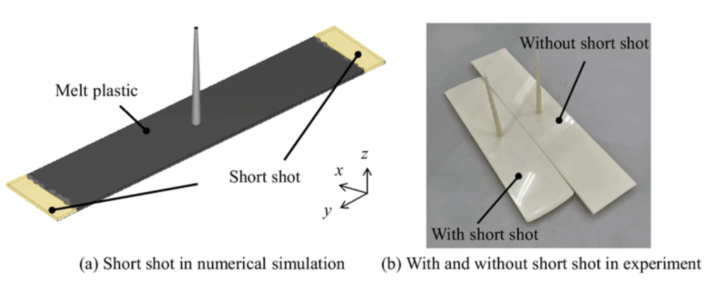
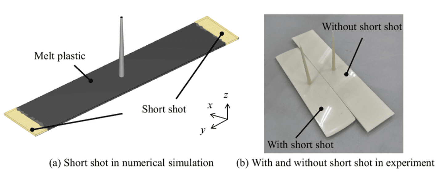
Short shots occur when the mould cavity isn’t fully filled, leaving incomplete sections or missing features. This typically affects thin-walled or distant areas and results in scrapped parts.
Root Causes: Thin or narrow sections, abrupt transitions, long flow paths, poor gate placement, low injection pressure, rapid cooling.
Design Fixes:
- Keep wall thickness consistent and ≥0.8 mm unless your resin supports thinner walls.
- Use radii and smooth transitions instead of sharp corners to maintain flow.
- Avoid long, narrow paths—add flow leaders or adjust gate placement to reduce travel distance.
- Simulate flow with MouldFlow or equivalent tools during design validation.
- Design ribs and bosses with proper fill ratios; rib thickness should be ~60% of adjacent wall thickness.
#2 Flash
Flash forms when plastic seeps into mould gaps, creating thin fins along parting lines, ejector pins, or gates.
It’s often cosmetic but may require post-processing or lead to tolerance issues if excessive.
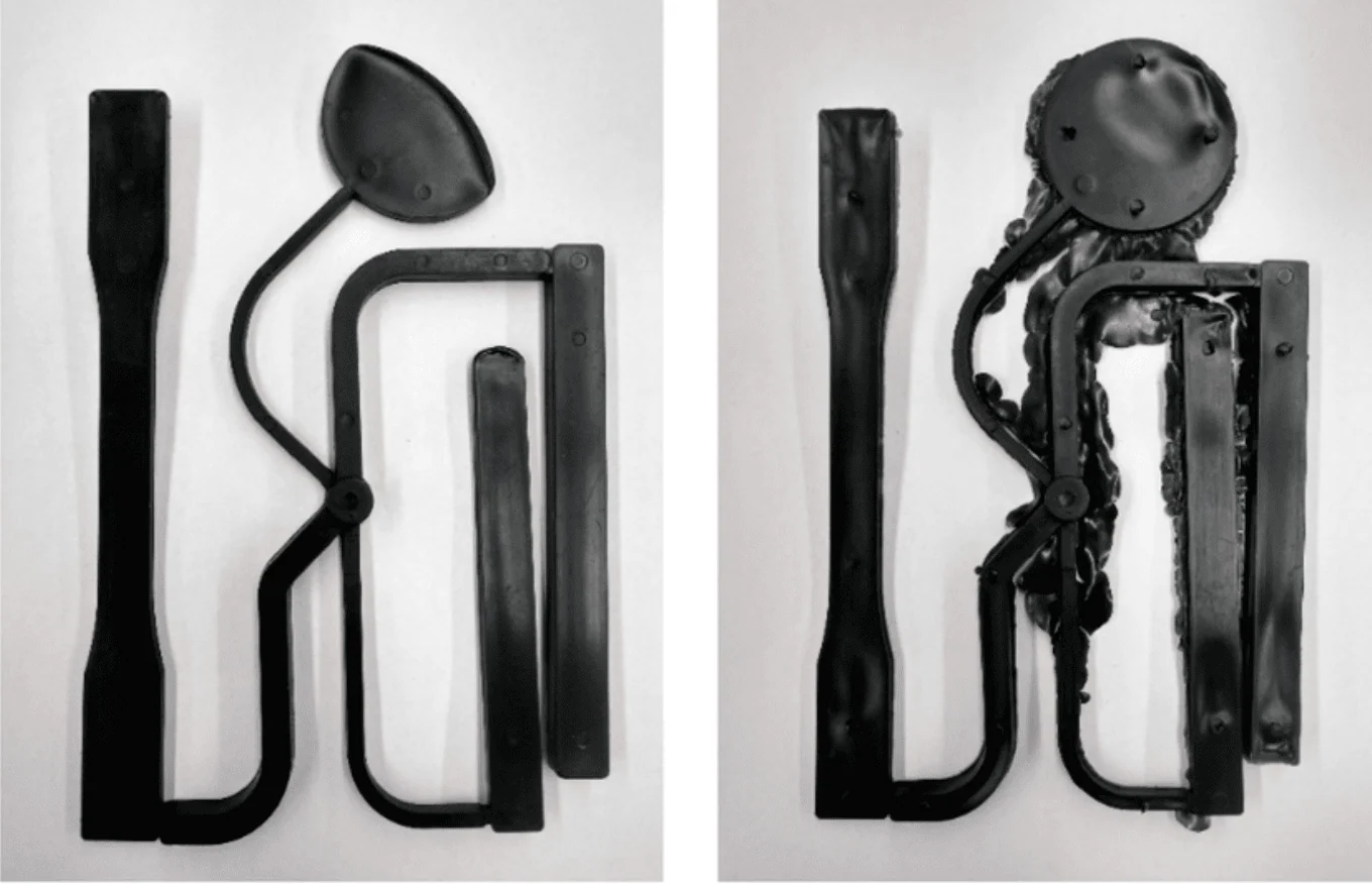
Root Causes: Excessive injection pressure, poor mould fit, worn tooling, sharp transitions at shut-offs, overly complex parting geometry, tolerance stacking.
Design Fixes:
- Place parting lines away from sharp corners and cosmetic zones.
- Apply consistent draft angles to avoid tight or mismatched shut-offs.
- Keep wall transitions near parting lines gradual to avoid local pressure buildup.
- Validate parting line placement early with a DFM review.
- Confirm that injection pressure and clamp force won’t exceed mould tolerances—simulate if needed.
#3 Improper Parting Line Placement
A parting line is where two mould halves (core and cavity) meet. Incorrect parting line placement can create visible seams or flash, especially if it crosses functional or cosmetic features. It can lead to poor fit, extra finishing, or aesthetic defects.
Root Causes: Incomplete DFM analysis, mismatched mould alignment, overlooked geometry transitions.
Design Fixes:
- Plan parting lines early—before locking aesthetic or functional geometry.
- Avoid placing parting lines over logos, snap-fits, sealing surfaces, or alignment features.
- Align parting lines with sharp edges, ribs, or recesses to naturally hide them.
- Use symmetrical parting lines where possible to balance ejection forces.
- Validate placement in DFM review and confirm mould opening direction.
#4 Bubbles and Voids
These appear as visible bubbles or hidden voids and reduce strength, cause dimensional errors, or leave surface blemishes. They’re often due to trapped air or uneven cooling. It can weaken structural integrity, compromise dimensional accuracy, and affect final appearance.
Root Causes: Moisture in resin, poor venting, sudden thickness changes, inconsistent wall design, high-shrinkage materials.
Design Fixes:
- Maintain consistent wall thickness—limit variation to ±10%.
- Avoid abrupt thick-to-thin transitions; taper gradually to ensure uniform flow and cooling.
- Add ribs to replace solid masses and promote even packing.
- Use venting features in deep or enclosed areas.
- Choose materials with low shrinkage for thick geometries (e.g., use ABS over HDPE).
- Simulate filling and cooling behavior to detect and eliminate air-trap zones.
#5 Gate Vestige
Gate vestige is a visible mark or protrusion where the plastic was injected. While minor, it can affect aesthetics or function in tight-fitting assemblies.
Root Causes: Oversized gates, poor gate placement, manual trimming, exposed gate on cosmetic surfaces.
Design Fixes:
- Place gates on non-cosmetic or hidden surfaces—inner walls, underside flanges, or recessed areas.
- Use tunnel or submarine gates for automatic vestige removal.
- Plan trimming method and location during the DFM stage.
- Integrate flat or ribbed features near gates to visually mask vestige.
- Specify surface finish or gloss level around the gate to reduce visibility.
Injection Moulding Defects Caused By Process
Process-related defects commonly result from improper control or incorrect settings within the moulding cycle. Variables such as injection pressure, injection speed, mould/resin temperatures, cooling rates, and material conditions significantly influence these defects. Unlike mould design issues, process-related problems often can be mitigated through adjustments in machine settings—without extensive mould modifications.
Typical process-related defects include:
- Flow Lines
- Burn Marks
- Warping
- Vacuum Voids
- Sink Marks
- Weld Lines (Knit Lines)
- Jetting
- Discolouration
- Surface Delamination
- Splay Marks (Silver Streaking)
By clearly differentiating mould design-related defects from process-related defects, engineers can effectively pinpoint root causes, streamline troubleshooting, and consistently achieve optimal injection moulding quality.
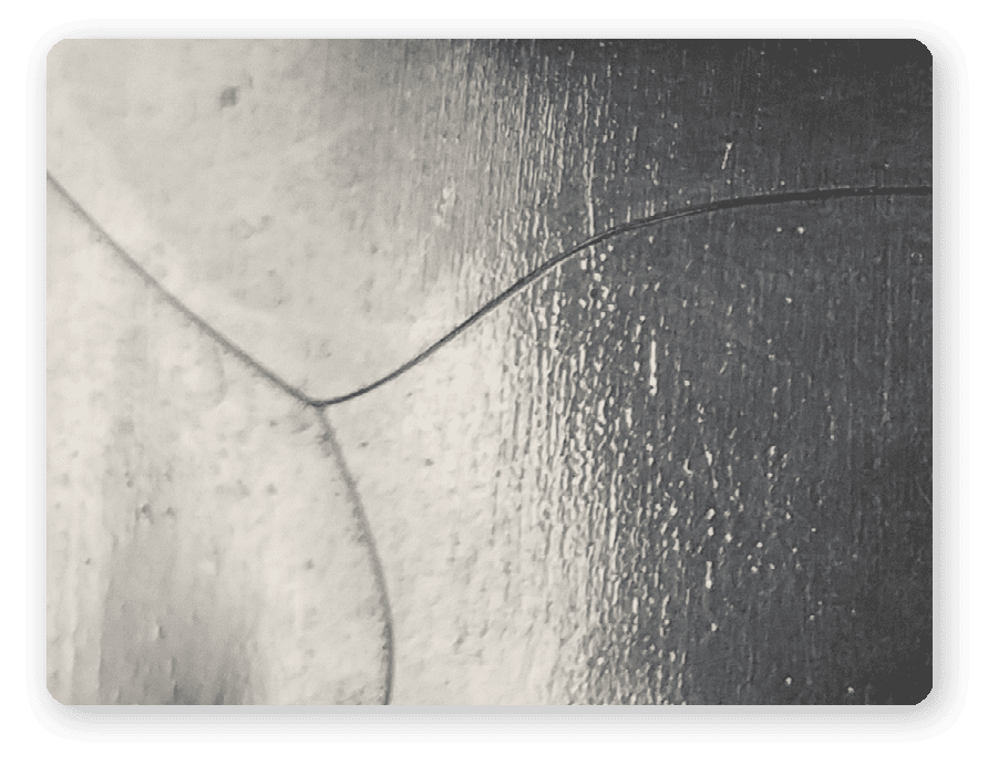
#6 Flow Lines
Flow lines appear as streaks or wavy patterns on the surface of moulded parts. These visual defects often show up near gates, corners, or holes where the molten plastic changes direction or slows down. While processing conditions are often the primary cause, design flaws can make flow lines worse or more likely to occur.
Design Fixes:
- Keep wall thickness uniform to support stable flow and reduce velocity fluctuations.
- Use gradual transitions between thick and thin sections to avoid directional turbulence.
- Avoid abrupt geometry changes; round off corners with fillets at least equal to wall thickness.
- Position gates strategically in thicker sections to maintain temperature and flow consistency.
- Avoid thin sections far from the gate—they cool faster and are prone to visible flow fronts.
Things To Keep in Mind During Manufacturing:
- Improper venting may trap air and disrupt smooth filling.
- Inadequate mould temperature or low injection speed causes premature cooling.
- Poor gate placement or size leads to inconsistent material flow.
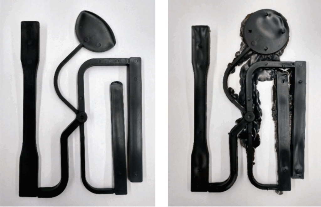
#7 Burn Marks
Burn marks are process-related injection moulding defects that appear as yellowish, brown, rusty, or black discolouration on the surface of moulded parts—often near the end of the flow path or around air traps. While primarily considered aesthetic flaws, in more severe cases, they may indicate localised overheating that leads to polymer degradation and even structural weakness in the affected areas.
Design Fixes:
- Trapped air due to poor venting: Improve venting channels or add air escape vents to allow gases to exit the mould cavity safely before resin arrival.
- Excessive injection speed or pressure: Reduce injection speed and pressure slightly to prevent rapid compression of air pockets that leads to overheating and ignition.
- Excessive melt or mould temperature: Lower the melt temperature or optimise cycle time to avoid polymer degradation near air traps.
- Contaminants or degraded material in the mould: Clean mould surfaces and avoid using degraded resin to prevent burnt residues that mimic burn marks.
- Improper runner or gate design: Redesign runners and gates to ensure smooth resin flow and reduce the chance of air entrapment in dead zones.
Things To Keep in Mind During Manufacturing:
If burn marks consistently appear in the same area of a part, consider relocating the gate or modifying the flow path to avoid trapping air in that region—this simple design adjustment can significantly reduce thermal buildup and eliminate burn-related discolouration.
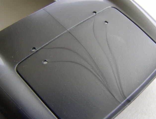
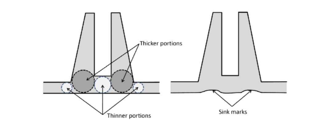
#8 Sink Marks
Sink marks are small depressions or dimples that form on the surface of a part, typically in thicker areas or near ribs and bosses. These defects occur when the outer surface of the part cools and solidifies faster than the interior, which continues to shrink and pulls the surface inward.

Design Fixes:
- Minimise wall thickness in thick areas to promote even cooling.
- Apply proper design rules for ribs and bosses: rib thickness should be no more than 50–70% of the adjoining wall.
- Avoid stacking thick features (e.g., bosses on top of ribs) unless absolutely necessary.
- Use coring techniques to remove excess material in thick sections without compromising strength.
- Collaborate with your manufacturer to optimise gate placement and ensure sufficient packing pressure in key regions.
- Choose materials like ABS, polycarbonate (PC), PMMA (acrylic)
Things To Keep in Mind During Manufacturing:
- Inadequate cooling time or uneven mould temperature can lead to internal shrinkage.
- Excessive material thickness in local areas traps heat, causing delayed solidification.
- Low injection pressure or packing pressure reduces the ability to compensate for shrinkage.
- Semi-crystalline plastics (like PA, POM, PP) tend to shrink more and are more prone to sink marks.
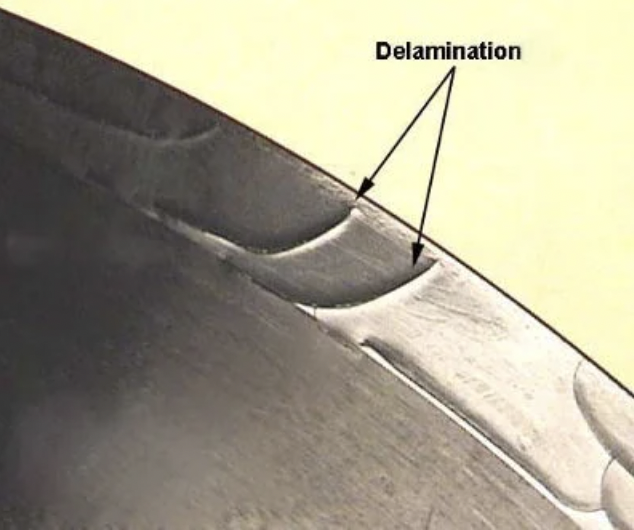
#9 Surface Delamination
Surface delamination appears as peeling or flaky surfaces caused by contamination or incompatible materials that prevent proper adhesion between plastic layers.
Design Fixes:
- Avoid combining incompatible resins or overmoulding dissimilar materials.
- Use single-material designs unless overmoulding is proven compatible.
- Minimise the use of release agents that can interfere with bonding.
- Confirm material compatibility with your supplier before prototyping.
Things To Keep in Mind During Manufacturing:
- Dry hygroscopic materials thoroughly.
- Purge machines between material changes.
- Keep hoppers, nozzles, and barrels clean to prevent contamination.
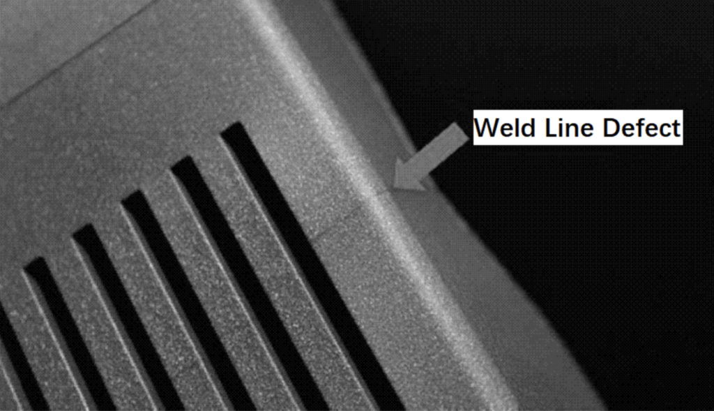
#10 Weld Lines (Knit Lines)
Weld lines (or knit lines) appear where two melt fronts meet but don’t fully bond, leaving behind visible seams or structural weaknesses.
This defect is especially common in parts with complex geometries, multiple gates, or features that interrupt the flow of plastic (e.g., holes, bosses, or ribs).

Design Fixes:
- Minimise the number of flow fronts by simplifying geometry and reducing obstructions.
- Place gates to direct flow so that convergence occurs away from high-stress zones.
- Use ribs or bosses near weld lines to improve mechanical strength.
- Avoid holes, inserts, or abrupt geometry changes that split flow unnecessarily.
Things To Keep in Mind During Manufacturing:
- Increase mould and melt temperatures to improve flow front bonding.
- Adjust injection speed to delay solidification at convergence zones.
Improve venting around potential weld line locations.
#11 Warping
Warping refers to visible bending, twisting, or bowing of the moulded part. It happens when different sections of the part cool and shrink unevenly, resulting in internal stresses that distort its shape.

Design Fixes:
- Use uniform wall thickness throughout your design to ensure consistent cooling.
- Avoid large, flat surfaces without ribs or curvature—they’re more prone to deformation.
- Add structural supports such as ribs to reduce warpage while keeping the part lightweight.
- Choose low-shrinkage materials like filled resins for better dimensional stability.
- Reduce sharp transitions between thick and thin walls to avoid differential cooling rates.
Things To Keep in Mind During Manufacturing:
- Balance cooling channels across the mould.
- Use temperature-controlled mould circuits to reduce cooling rate differences.
- Lower mould temperatures and increase packing pressure where applicable.
#12 Jetting
Jetting creates snake-like surface defects caused by high-speed melt streams entering the cavity and cooling before they fuse with surrounding material.
This defect not only affects the aesthetics of the moulded part but can also create localised areas of weakness due to incomplete bonding between the layers of material.
Design Fixes:
- Use overlap or fan gates to reduce flow velocity at entry.
- Choose smoother transitions between wall sections and avoid sharp corners.
- Use gradual fillets at inlets and reduce wall thickness jumps.
- Lower initial fill rates during the prototype phase to assess flow behavior.
Things To Keep in Mind During Manufacturing:
- Decrease injection speed at the start of the cycle.
- Increase mould temperature to allow better fusion.
- Optimise gate dimensions to reduce direct impingement.
#13 Vacuum Voids
Vacuum voids are internal air pockets within the part. While not always visible, they can weaken structural integrity.
Design Fixes:
- Avoid thick, solid cross-sections. Use hollowed-out shapes where possible.
- Add coring features or internal channels to reduce bulk material.
- Plan for venting where air entrapment is likely.
- If internal voids are critical, request micro-CT or sample-cut inspection.
Things To Keep in Mind During Manufacturing:
- Improve mould venting and use gas-assist injection if needed.
- Adjust packing pressure and holding time to eliminate trapped air.
- Use slower injection speeds to allow air escape.
#14 Discolouration
Discolouration is any unwanted colour variation on the moulded part, often due to resin degradation, contamination, or inconsistent colouring agents.
Design Fixes:
- Use stable, well-tested colourants with high thermal resistance.
- Avoid designing parts that require frequent colour transitions.
- Clearly specify RAL or Pantone codes and masterbatch ratios in documentation.
- Limit complex multi-material zones where colour control is critical.
Things To Keep in Mind During Manufacturing:
- Maintain proper barrel temperature profiles.
- Clean the screw and barrel between different colour batches.
- Use proper dosing equipment for colourants or masterbatch.
#15 Splay Marks (Silver Streaking)
Splay marks are silvery streaks on the surface, typically near gates. They result from moisture, contamination, or excessive shear in the resin.
Design Recommendations:
- Avoid abrupt transitions or sharp corners near gates.
- Add venting space around the gate area to allow moisture release.
- Choose materials with low moisture absorption or include drying protocols in sourcing.
Things To Keep in Mind During Manufacturing:
- Pre-dry hygroscopic materials like PA, PC, and ABS.
- Reduce injection speed to minimise shear.
- Clean hopper and dryer filters regularly.
#16: Contamination
Contamination occurs when foreign substances embedded in the molten material during processing. These defects often appear as dark spots, streaks, or unexpected inclusions on the part surface—and in some cases, they affect the part’s strength or dimensional stability.
Contaminants typically enter the process through poor material handling, improper tooling and equipment maintenance, or wear-related debris.
Design Fixes:
- Avoid unnecessary material changes and colour switches unless required.
- Limit deep ribs or narrow features where contaminants can become trapped or accumulate.
- Add draft angles to internal features for better flow and material flushing.
- Specify consistent resins across part families to reduce cleaning cycles and purge times.
- Use internal quality checks (e.g. material batch traceability) in designs requiring tight tolerances or visual precision.
Things To Keep in Mind During Manufacturing:
- Schedule regular machine maintenance to detect and fix tooling wear.
- Maintain a clean, oil-free production environment to reduce airborne contamination risk.
- Clean hoppers, barrels, and screw assemblies regularly to prevent buildup.
- Store resins in sealed, dry containers to prevent airborne dust and moisture exposure.
- Purge thoroughly between different resins or colourants to prevent cross-contamination.
Injection Moulding Defects by Severity and Cost Impact
| Defect Type | Structural Impact | Cosmetic Impact | Production Risk | Typical Cost Increase |
| Short Shots | High | Medium | High | ↑↑ (part rejected) |
| Flash | Low | Medium | Low | → (trimming required) |
| Improper Parting Line Placement | Medium | Medium | Medium | ↑ (mould rework) |
| Bubbles & Voids | Medium | Medium | Medium | ↑ (mould/process changes) |
| Gate Vestige | Low | Medium | Low | → (finishing/gate changes) |
| Flow Lines | Low | High | Low | → (process adjustments) |
| Burn Marks | Medium | High | Medium | ↑ (process tuning) |
| Sink Marks | Medium | High | Medium | ↑ (tool redesign) |
| Delamination | High | Medium | High | ↑↑ |
| Weld Lines | Medium | Medium | Medium | → |
| Warping | High | High | High | ↑↑ (rework or scrap) |
| Jetting | Medium | High | Medium | ↑ |
| Vacuum Voids | High | Low | Medium | ↑ (tool redesign) |
| Discolouration | Low | High | Low | → |
| Splay Marks | Low | High | Low | → (drying/parameter fixes) |
Avoiding injection moulding defects isn’t just about technical precision and design—it’s also about working with a partner who anticipates problems before they happen.
Have you encountered injection moulding defects in your own projects?
Share your experience or insights with the Xometry Pro community. Your story might help another engineer design better, faster, and smarter.


Comment(0)