Stereolithography (SLA) is a resin-based 3D printing technology that uses a UV laser to selectively cure liquid photopolymer resin layer by layer. SLA stands out for its ability to produce parts with extremely fine details, smooth surfaces, and tight tolerances—often requiring little to no post-processing. It supports various materials, including general-purpose resins, high-temperature resins, and transparent options.
These properties make it ideal for prototyping, master patterns for molding, dental models, small mechanical components, and aesthetic design parts. However, SLA parts are generally less UV-stable than those made with thermoplastic-based processes.
1. Respect SLA Minimum Feature Sizes
While SLA 3D printing excels at fine details, extremely small features can still lead to issues during production. Thin pins may become fragile, narrow slots can be poorly defined, and small holes might seal shut due to resin accumulation during the printing process. These defects are often the result of pushing geometry below reliable limits.
Rule of Thumb:
- Keep a minimum reliable pin diameter of 1 mm.
- A minimum slot size of 0.5 mm is recommended, but the bigger, the better.
- Keep a minimum printable feature size of 0.2 mm.
2. Design with Appropriate Wall Thickness
Wall thickness is one of the most crucial factors in SLA 3D printing design. Too thin walls may make the parts fragile or possibly break during printing. On the other hand, too thick ones lead to material wastage and some defects such as warping.
Additionally, nonuniform walls cool at different rates, with thinner sections cooling faster than thicker ones. This means the walls should be correctly sized and thickness maintained uniformly throughout the profile to avoid cracking, warping, and other defects.
Unsupported walls, which are at a higher risk of warping or breaking off, should be thicker. They can also be designed with fillet bases to enhance their mechanical strength. Supported walls are less likely to warp, meaning they can be thinner, but there should be a limit.
Rule of Thumb:
- Keep the minimum recommended thickness of 0.6 mm for unsupported walls.
- Keep the minimum recommended thickness of 0.4 mm for supported walls.
3. Account for SLA Tolerances in Mating Parts
Although SLA 3D printing can achieve high precision, it is still crucial to mind tolerances when designing parts. Factor in tolerances and account for shrinkage during curing.
This is the only way to comply with tight tolerances and ensure parts function properly. Adequate clearance should be designed between mating parts to prevent them from fusing when being printed. This also aids in the seamless assembly of parts.
Rule of Thumb:
- Ensure minimum clearances of 0.5 mm between moving parts and assembly.
- Use 0.1 mm clearance to give a push or snug fit.
4. Hollow SLA Parts to Save Resin Safely
SLA can produce fully solid parts, but in many cases, hollowing the design helps reduce material usage and printing time. However, hollow sections must be designed carefully to maintain structural integrity and avoid common printing issues. Thin walls or fully enclosed cavities can trap uncured resin inside the part, leading to internal pressure imbalances that may cause cracks or even part failure. In addition, hollow or concave shapes printed face-up on the build platform can create a suction effect against the resin tank, which may cause the part to detach during printing.
To avoid these issues, always include drainage holes to let excess resin escape and minimize suction forces. For fully enclosed features like spheres or cavities, consider either filling the hollow or placing at least one drainage hole in each hollow section.
Rule of Thumb:
- Keep a minimum wall thickness of hollow sections of 2 mm.
- Drainage holes should be at least 3.5 mm in diameter.
- Include at least one drainage hole per hollow section.
5. Round Internal and External Corners
Sharp corners and edges on parts increase stress concentrations. This increases the chances of cracks forming and ultimate part failures. Rounding both internal and external corners distributes stress evenly through the structure. Make the radii as large as possible to encourage efficient stress distribution in SLA 3D printed parts.
Rule of Thumb:
- Aim for a minimum radius of about 0.5 mm for the corners.
- The radius of an internal corner should be at least half the thickness of the associated wall.
- The radius of the external corners should be at least 1.5 times the thickness of the associated walls.
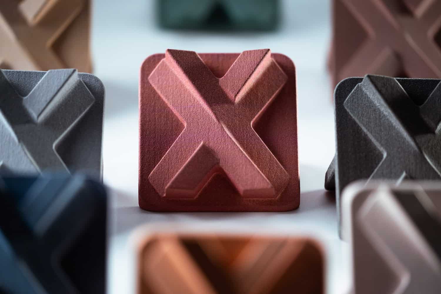
6. Add Clear Text and Markings
SLA is well-suited for adding small logos, labels, or functional text directly onto a part’s surface. Embossed or engraved text that’s too fine can lose contrast or become unreadable due to overcuring or resin bleed.
To ensure legibility, text should have enough depth or height to withstand minor surface smoothing while still remaining crisp and visible in the final part.
Rule of Thumb:
- Embossed features must be at least 0.5 mm in height and 0.4 mm wide.
- Engraved features require a minimum depth of 0.5 mm and a width of 0.5 mm.
- Minimum font size: 1 mm character height, but 2 mm or higher is recommended
7. Minimize and Strategically Place Supports
Support structures are discouraged in SLA design because they leave footprints on the parts.
However, there are instances when they are necessary, such as walls and overhangs. Support structures are easy to add since most slicing tools can detect their rightful positions.
Don’t add support structures unnecessarily. If it is necessary to print with support structures, follow the recommended minimum length and angle for such features. Going beyond the limits can cause the overhanging features to break off during peeling.
Rule of Thumb:
- Unsupported overhangs must not be more than 2 mm in length and must be at a minimum angle of 30°.
- Place supports under overhangs, bridges, and any features that may deform or lose shape due to lack of support during printing.
- Use smaller touchpoints for support to reduce marks on the finished part.
8. Orient Parts to Minimize Supports and Improve Finish
In SLA 3D printing, part orientation affects print success, mechanical strength, and the visibility of support marks. Well-oriented parts are easier to print, require fewer supports, and are less prone to failures like warping, suction issues, or weak adhesion. Orienting parts at an angle also helps resin flow off the surface more evenly and reduces the risk of cupping or internal stress buildup.
Rule of Thumb:
- Position parts to reduce overhangs that require support.
- Avoid large flat surfaces parallel to the build platform.
- Angle the part between 30°–45° to promote adhesion and reduce print stress
Avoid Cupping in SLA Design
A common issue specific to the inverted SLA printing process is cupping. This occurs when a hollow or concave feature—such as a recessed pocket or an enclosed cavity—faces downward toward the resin vat. As the part is peeled from the resin tank layer by layer, the cavity can trap air or uncured resin, creating a suction effect.
This pressure differential may lead to a blowout, where internal pressure causes a wall to rupture outward during printing. In severe cases, cupping can damage the part, the resin vat, or even cause resin spills inside the machine.
To reduce the risk:
- Avoid cup-like geometries with downward-facing openings.
- Add drainage holes to vent enclosed volumes.
- Reorient parts so that hollow or concave surfaces don’t face directly toward the vat.
SLA 3D Printing Specifications Reference Guide
The table below provides a quick summary of SLA 3D design specifications at Xometry for various part features. These are all vital to consider during the design phase for high-quality prints.
| Specifications | Details |
| Maximum build volume | Standard: 145 × 145 × 185 mm Industrial: 736 x 635 x 533 mm |
| Minimum feature thickness | 0.20 mm |
| Suggested minimum wall thickness | 0.4 mm (supported walls), 0.6 mm (unsupported walls) |
| Layer thickness | 20-100 microns (depending on the printer) |
| General tolerance | ±0.5% (±0.2 mm) (Standard) ±0.5% (±0.15 mm) (Industrial) |
Get Your High-Quality SLA 3D-Printed Parts at Xometry
Mastering SLA 3D printing opens up a world of possibilities for creating detailed, high-precision parts with smooth finishes. By adhering to the design tips in this guide, you can achieve exceptional results, ensuring that the printed parts are more functional, durable, reliable, and interchangeable. These tips are key to complying with high industry standards.
Are you ready to take your projects to the next level? Unlock the full potential of your ideas by partnering with Xometry for unparalleled quality and expertise in SLA 3D printing.
 Europe
  Türkiye
  United Kingdom
  Global

 Login with my Xometry account
  0
0










Comment(0)