 Europe
  Türkiye

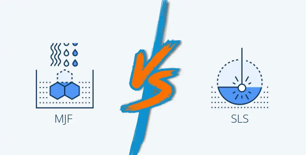
Fused Deposition Modeling (FDM) is one of the most cost-effective 3D printing technologies, making it a popular choice for prototyping, functional testing, and small-scale production. However, when higher quantities, better repeatability, or faster production speeds are required, industrial processes like SLS or MJF (using materials such as PA 12) are more suitable. While FDM is highly versatile, its printing speed is limited compared to these technologies, making it less ideal for large-scale serial production. Nonetheless, its affordability and material options make it a valuable solution for many applications.
1. Ensure Proper Wall Thickness
One of the most common mistakes in FDM 3D printing is using walls that are too thin or too thick. Overly thin walls warp and require the use of a support structure, which adds to the production cost. Also, designing parts with excessively thick walls requires more materials to produce. You want to keep the cost at a minimum by optimizing the design.
Rule of thumb:
- Design walls at least 0.75-1.00 mm thick, or three times the nozzle diameter.
- Use cross-hatch inner structures instead of solid walls to reduce material use and weight.
2. Optimize Overhangs and Bridges
FDM 3D printing builds parts layer by layer, meaning that each new layer must be adequately supported by the one below it. Overhangs and bridges—features that extend outward or span gaps without direct support—can sag, curl, or produce rough surfaces if not properly designed. This occurs because molten thermoplastic behaves like a semi-liquid when extruded, and without enough underlying material, gravity pulls it down before it fully solidifies.
To ensure high-quality prints and avoid defects, designers should minimize unsupported overhangs and bridges or use support structures strategically.
Rule of thumb:
- Overhangs exceeding the maximum overhang angle of 45° require support
- Bridges longer than 5 mm may need additional supports or design adjustments.
- Chamfer or round edges to improve overhang printability.
3. Minimize Warping with Proper Design
Warping is one of the most common defects in FDM 3D printing, occurring when the printed part cools unevenly, leading to material shrinkage and deformation. As thermoplastic cools, it contracts slightly, and if different areas cool at different rates, internal stresses build up, causing the part to lift off the print bed or distort. Warping is particularly problematic for large flat surfaces and materials with high thermal expansion, such as ABS.
Rule of thumb:
- Optimize material choice (e.g., PLA or PETG warps less than ABS).
- Avoid large, flat areas—add fillets or chamfers to reduce internal stress.
- Use brims, rafts, or skirts to improve bed adhesion.
4. Use Support Structures Wisely
Support structures are necessary for printing complex geometries, overhangs, and bridges, but poorly placed support material can be difficult to remove, leave surface imperfections, and increase print time. Instead of relying on excessive supports, optimizing part orientation and minimizing support material helps improve print quality and reduce the need for post-processing operations.
Rule of thumb:
- Orient parts to reduce the need for support.
- Use tree or soluble supports for easier removal.
- Place supports away from critical surfaces to minimize post-processing.
5. Orient Parts for Strength and Surface Quality
FDM parts are weakest along the Z-axis due to layer adhesion limitations. This means that parts tend to break along their printed layers when exposed to tensile or bending forces. Additionally, print orientation affects surface smoothness—visible layer lines are more pronounced on curved and angled surfaces.
Rule of thumb:
- Brittle features should always be parallel to the build platform.
- Orient holes vertically to reduce the need for support structures.
- Align curved or angled surfaces parallel to the build platform to minimize stair-stepping.
6. Proper Clearance for Mating Parts
Mating parts in FDM 3D printing require careful clearance design to ensure a proper fit without fusing together or being too loose.
Due to thermal expansion, layer variations, and printer tolerances, designing parts with exact nominal dimensions can lead to unexpected fit issues.

Rule of thumb:
- 0.5 mm clearance for an interference fit.
- 0.2–0.3 mm clearance for a sliding fit.
- Consider a similar orientation for the components to be printed as an assembly. Also, ensure the interfacing surface is perpendicular (vertical) to the build platform.
- Consider splitting intricate 3D models into several pieces to be printed one at a time when it is impossible to provide the minimum required clearance.
7. Design Columns, Pins, and Small Features with Printability in Mind
Small, thin features like columns and pins are often too fragile to survive the FDM printing process, especially if they fall below the printer’s resolution limits. They may snap during post-processing or fail mid-print due to insufficient support.
Choosing the right material properties, print orientation, and minimum feature sizes can help prevent these issues.
Rule of thumb:
- Design columns with a minimum diameter of 2–3 mm.
- Pins should be at least 1 mm in diameter and kept as short as possible.
- Use PLA or high-detail materials for small intricate features.
- Use support structures for minimum-sized features to improve stability.
8. Add Fillets and Chamfers to Reduce Stress Concentration
Sharp corners act as weak points in FDM-printed parts, creating areas of high-stress concentration where cracks can initiate. This is particularly critical in load-bearing components where failure could compromise performance.
Adding fillets (rounded corners) and chamfers (angled edges) distributes stress more evenly, reducing breakage and improving durability.
Rule of thumb:
- Ensure fillet radius matches wall thickness for consistent strength.
- Avoid fillets on the first few layers to prevent warping.
- Use chamfers instead of sharp edges to improve part strength and ease of removal.
- Add chamfers and fillets to overhang surfaces larger than 45° to eliminate the need for support.
9. Use Bosses and Ribs to Strengthen Parts Without Excess Material
Bosses (cylindrical protrusions) and ribs (thin vertical supports) enhance part strength without increasing material use. Bosses serve as mounting points and hubs for fasteners or connectors, while ribs provide additional structural support to reinforce weak sections. These features help improve durability while reducing overall weight and print time.
Rule of thumb:
- Bosses should match part thickness or be 0.5 mm smaller.
- Always use ribs to reinforce bosses for added strength.
10. Proper Sizing of Embossed and Engraved Text
Embossed and engraved text/logos can be difficult to read if designed too small. FDM printers lack the fine resolution of technologies like SLA, so text features should be large enough for clear reproduction.
Rule of thumb:
- Embossed text: 0.8 mm thickness, 0.5 mm height.
- Engraved text: 1.0 mm thickness, 0.5 mm depth.
- The text should be placed on the top surfaces of the part rather than vertical walls for better legibility.
- Use bold, sans-serif fonts like Arial, Century Gothic Bold, or Verdana for clarity.
FDM Technology Specifications Reference Guide
FDM 3D printing technology has its limitations, which depend on the printer’s capabilities. The following table summarizes key specifications you should always remember when designing 3D models for printability using this technology.
| Specification | Details |
| Maximum build volume | Up to 900 x 600 x 900 mm. Standard: 350 x 350 x 350 mm. Industrial: 900 x 600 x 900 mm |
| Minimum feature thickness | 1 mm |
| Suggested minimum wall thickness | 0.75 mm (supported), 1.00 mm (unsupported) |
| Layer Thickness | 0.25 – 0.33 mm |
| General tolerance | ±0.5% (±0.5 mm) |
Get Your Designed Parts 3D-Printed at Xometry
The quality of 3D-printed does not depend only on the design. You might consider all the best FDM design practices highlighted in this article but still end up with defective parts. This often happens during the printing process. If the material used is not up to the standards and the incorrect temperature settings are used, you can expect a compromise in quality.
Letting industry experts handle the printing process guarantees high-quality parts. By choosing Xometry, you benefit from a combination of expertise, advanced technology, and efficient processes, ensuring your designs are brought to life with the highest quality and precision. Our streamlined processes and competitive pricing help reduce material wastage and overall costs. Get an instant quote for our advanced FDM 3D printing service that ensures strong, durable parts customized to meet your specific requirements.

Comment(1)