 Europe
  Türkiye


Angularity is a geometric tolerance in Geometric Dimensioning and Tolerancing to control the orientation of one feature relative to another. It is one of the 14 standard GD&T tolerances defined in ASME Y14.5.
GD&T tolerances can be broadly categorized into five different groups: form, orientation, location, profile and runout. Angularity falls under the orientation group alongside parallelism and perpendicularity.
This article focuses on the angularity tolerance, covering its importance, applications, measurement methods and other pertinent topics.
What is Angularity?
Angularity is a geometric tolerance that controls the orientation of a feature (a surface, axis, or center plane) at a specified angle relative to a datum. Because an angular orientation cannot exist in isolation, angularity must always be defined relative to a reference feature (datum).
While parallelism and perpendicularity are used when features are oriented at exactly 0° or 90° to each other, angularity is used for all other acute and obtuse angles.
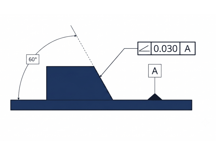
It is a common design mistake to confuse angularity with a standard angular dimension tolerance (e.g., ±2°). The angularity tolerance zone is not inherently angular. Instead, the target angle becomes a basic dimension (a theoretically exact angle), and the angularity callout creates a uniform tolerance zone around this basic angle. This zone indirectly controls the feature’s orientation by restricting where it can lie based on the datum.
Depending on the feature, angularity creates either a 3-dimensional tolerance zone comprising two parallel planes or a cylinder. It is commonly used to control a surface relative to a reference surface or axis, but it can also control an axis or a center plane. These variations are referred to as surface angularity, axis angularity, and center plane angularity.
In certain scenarios, angularity is used alongside position tolerance if the orientation requires tighter control than what the position tolerance alone provides. However, for most features of size (like holes), a position tolerance inherently controls both location and orientation relative to the datum reference frame.
Applications of Angularity
Angularity is applied across three feature categories, each with distinct functional goals and inspection approaches.
| Angularity Type | Controlled Feature | Typical Functional Requirement | Common Industrial Examples |
| Surface Angularity | Planar surface at a non-0°/90° angle to the datum | Consistent mating contact, sealing, or load transfer across an inclined face | Dovetail slide bevels, valve seat faces, wedge clamping surfaces, chamfer mating flanges |
| Axis Angularity | Derived median line of a cylindrical feature of size (hole, pin, shaft) | Angular alignment of a bore or pin axis to ensure correct mating with a corresponding feature on an assembly | Angled oil passages in engine blocks, inclined dowel pin bores, hydraulic manifold ports, medical implant screw channels |
| Center Plane Angularity | Derived median plane of a rectangular feature of size (slot, tab, key) | Angular tracking of a slot or tab median plane to prevent binding or misalignment under load | Angled keyways, tilted mounting flanges, inclined bracket slots, tapered fixture pads |
Angularity Tolerance Zone
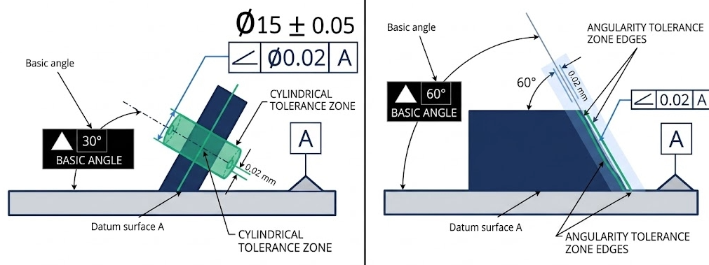
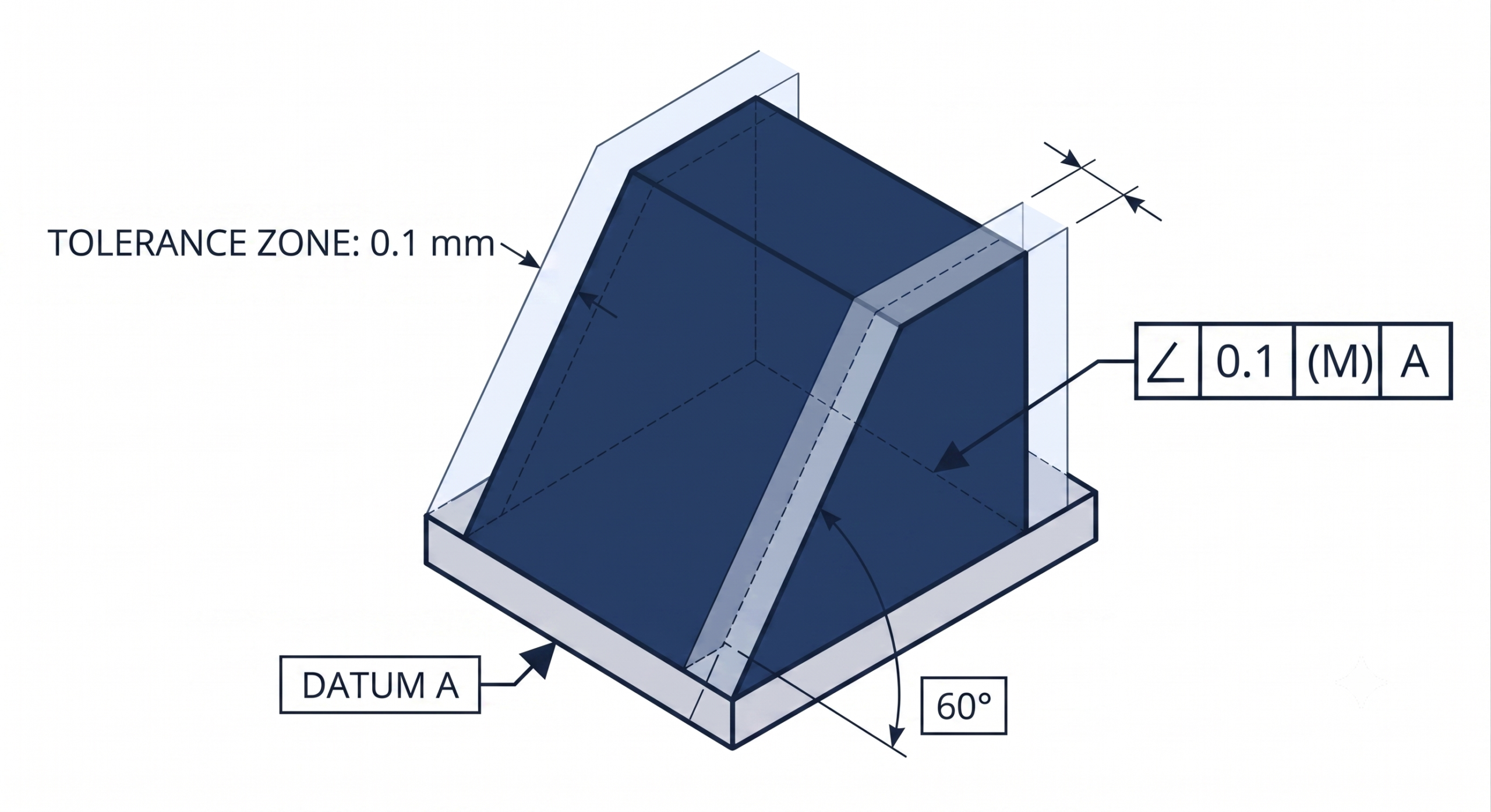
The angularity tolerance zone defines the limits of the controlled feature to meet the tolerance requirements. Two types of tolerance zone shapes are available in angularity – the default tolerance zone, comprising of two parallel planes and the cylindrical tolerance zone.
Parallel Planes Zone: Surface and Center Plane Angularity
For surface angularity, the zone consists of two parallel planes oriented at the basic angle relative to the specified datum. The controlled surface must have all of its points lie between these two planes. For center plane angularity, the zone is positioned at the derived median plane of the feature, which is the imaginary plane connecting the midpoints of all opposing surface pairs. The distance between the two planes is the stated tolerance value. A tolerance of 0.1 mm means all points on the controlled surface or derived median plane must reside within a band 0.1 mm wide, oriented at the basic angle to the datum.
Cylindrical Zone: Axis Angularity
For axis angularity, the tolerance zone becomes a cylinder whose axis is oriented at the basic angle relative to the datum. The derived median line of the controlled feature, the line connecting the center points of all cross-sections along its length, must fall entirely within this cylindrical zone. The diameter of the cylinder equals the tolerance value, and the diameter symbol (∅) is included in the feature control frame to signal the cylindrical zone explicitly. This zone controls angular deviation in all radial directions simultaneously, making it the correct choice for pins, studs, and bores that must orient precisely to mate with features on a mating component.
Projected Tolerance Zone for Threaded and Press-Fit Features
For threaded holes and press-fit bores, the relevant angular deviation is not the orientation of the hole itself but the tilt of the mating fastener or pin once installed. A hole can pass a standard angularity inspection yet still cause interference during assembly because the fastener projects beyond the part surface. The projected tolerance zone modifier (Ⓟ) addresses this by extending the cylindrical zone above the part surface by a specified height. A callout reading ∠ 0.1 Ⓟ 25 requires the axis to remain within a 0.1 mm cylindrical zone extending 25 mm above the hole exit, not within the hole depth. The projection height is set to equal or exceed the engagement length of the mating component.
Angularity Feature Control Frame
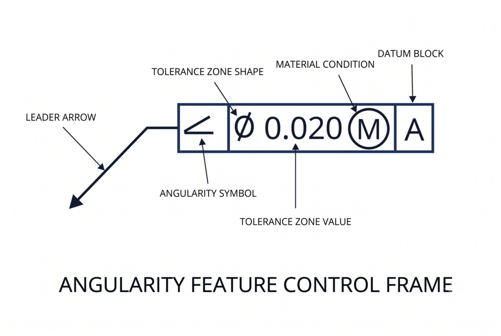

The angularity tolerance is applied to a feature using a feature control frame. The frame includes all the information needed to clearly define a tolerance. It consists of geometric characteristic symbols, the tolerance zone shape, the tolerance value, modifiers and datum feature reference letters where applicable, to define the geometric tolerance.
For surface angularity, the angularity callout, via a leader arrow, points directly to the feature. Alternatively, for planar surfaces, the leader line may connect the frame and the feature through an extension line from the feature.
As we deal with features of size in the case of axis and center plane angularity, the feature control frame is attached to the feature by an extension of the dimension line and may be placed adjacent to the size dimension.
A general feature control frame can be divided into three distinct blocks – the GD&T symbol block, the tolerance block, and the datum block.
GD&T Symbol
The first compartment contains the angularity geometric characteristic symbol, an acute angle mark (∠) opening to the right, as defined by ASME Y14.5. This symbol immediately identifies the tolerance as an orientation control requiring a datum reference and a basic angle.
Tolerance Value and Modifiers
The second compartment specifies the tolerance zone shape and value. For axis angularity, the diameter symbol (∅) precedes the numerical value to indicate a cylindrical zone. For surface and center plane angularity, no zone shape symbol is used, as the parallel planes zone is the default. The numerical value follows, representing either the width between the parallel planes or the diameter of the cylindrical zone in millimeters.
Material condition modifiers follow the tolerance value when the tolerance applies to a feature of size. Maximum material condition (MMC), denoted by a circled M, and least material condition (LMC), denoted by a circled L, are the two options. Regardless of feature size (RFS) is the default condition and requires no symbol. When no modifier appears, RFS applies, meaning the stated tolerance is fixed regardless of the feature’s actual manufactured size.
Datum References
The third compartment contains the datum reference letters in order of precedence: primary, secondary, and tertiary. Angularity requires at least one datum. A single datum constrains the part’s orientation relative to one reference plane or axis but leaves the part free to rotate about the axis perpendicular to that datum. A secondary datum locks that rotation. A tertiary datum locks translation along the remaining axis. For most angled surfaces and bores, two datums are required for a fully constrained and unambiguous inspection setup.
Datum features are selected for their stability, accessibility, and functional significance. The primary datum is typically the largest, most stable surface, restricting the maximum number of degrees of freedom. Symmetric parts may require only one datum, but features with directional load paths almost always require at least two.

Bonus Tolerance in Angularity
Bonus tolerance is an increase in the allowable geometric tolerance that becomes available when a feature of size departs from the material condition specified in the feature control frame. It applies only when a material modifier (MMC or LMC) is called in the tolerance block.
When angularity is called at MMC, the stated tolerance applies strictly when the feature is at its maximum material size, the smallest internal feature or largest external feature. A virtual condition boundary is established at this combination of MMC size and stated angularity tolerance. The feature must not violate this boundary. As the actual manufactured size departs from MMC toward LMC, the geometric tolerance can increase by an amount equal to the size departure without compromising the virtual condition boundary or the assembly fit.
The formula is direct:
Total Angularity Tolerance = Stated Tolerance + (Actual Size Departure from MMC)
| Feature Condition | Actual Bore Diameter (mm) | Departure from MMC (mm) | Stated Tolerance (mm) | Bonus Tolerance (mm) | Total Angularity Tolerance (mm) |
| MMC (smallest bore) | 20.000 | 0.000 | 0.1 | 0.000 | 0.100 |
| Intermediate | 20.050 | 0.050 | 0.1 | 0.050 | 0.150 |
| Intermediate | 20.100 | 0.100 | 0.1 | 0.100 | 0.200 |
| Intermediate | 20.150 | 0.150 | 0.1 | 0.150 | 0.250 |
| LMC (largest bore) | 20.200 | 0.200 | 0.1 | 0.200 | 0.300 |
Example parameters: Bore nominal 20 mm, tolerance ±0.100 mm (MMC = 20.000 mm, LMC = 20.200 mm), angularity stated at 0.1 mm at MMC.
Bonus tolerance reduces scrap rates and eases manufacturing process control without compromising assembly function. The virtual condition boundary remains fixed; it is the tolerance zone that expands as the part’s actual size moves away from the worst-case material condition.
Angularity vs Other Callouts
Angularity overlaps in scope with several other GD&T controls. Selecting the correct callout requires a precise understanding of what each control governs and what it ignores.
| Control | Group | Datum Required | Zone Geometry | Key Functional Scope | Use Angularity Instead When |
| Angularity | Orientation | Yes (min. 1) | Parallel planes or cylinder, at the basic angle | Controls orientation at any non-0°/90° angle; does not control location or form | The feature is neither parallel nor perpendicular to the datum |
| Parallelism | Orientation | Yes | Parallel planes or cylinder, at 0° to datum | Controls 0° orientation only; does not control location or form | Feature must be at a non-zero angle to the datum |
| Perpendicularity | Orientation | Yes | Parallel planes or cylinder, at 90° to datum | Controls 90° orientation only; does not control location or form | Feature must be at an angle other than 90° to the datum |
| Flatness | Form | No | Parallel planes, floating (no angular constraint) | Controls surface planarity independent of orientation or location | The surface must also maintain a specific angular relationship to a datum |
| Position | Location | Yes | Cylinder or parallel planes, at basic angle and location | Controls both location and orientation; covers angular variation implicitly for holes | Orientation alone requires tighter control than position provides, or the feature is a non-cylindrical surface |
| Profile of a Surface | Profile | Optional | Uniform bilateral or unilateral band around the true profile | Controls form, orientation, and location simultaneously along a complex surface | Only orientation control is needed, without size or location constraints |
Angularity vs. Parallelism and Perpendicularity
Parallelism and perpendicularity are special-case angularity callouts restricted to exactly 0° and 90° respectively. The tolerance zone mechanics are identical: two parallel planes or a cylinder oriented at the basic angle to the datum. The choice of callout is determined entirely by the basic angle. Using angularity at 0° or 90° is technically correct but considered non-standard practice; parallelism and perpendicularity are the preferred callouts for those orientations.
Angularity vs. Flatness
Both angularity and flatness use a tolerance zone of two parallel planes and both restrict surface variation. The distinction is foundational: flatness is a form control that has no datum, no orientation constraint, and no basic angle. A surface passes flatness if it lies within two parallel planes at any orientation. Angularity requires that those same two parallel planes be oriented at the specific basic angle relative to the datum. A surface can pass a flatness check at a measured deviation of 0.05 mm and still fail an angularity check if the surface tilts outside the angular tolerance zone. Tight angularity indirectly limits surface variation, but it is not a substitute for a flatness callout when form control is the primary requirement.
Angularity vs. Position
Position controls both the location and the orientation of a feature relative to the datum reference frame. For cylindrical features of size such as holes and pins, position tolerance inherently limits angular deviation because a displaced axis that tilts beyond the tolerance cylinder violates the positional boundary. Angularity is redundant in these cases unless the orientation requirement is tighter than the positional tolerance allows. The scenario where both are applied simultaneously is when features such as holes are located on an inclined surface: angularity controls the orientation of the inclined surface itself, and position controls the location of the holes on that surface. Both callouts are necessary for a complete definition.
How to Measure Angularity
Angularity measurement is mainly about checking whether a surface, axis, or center plane stays within a tolerance zone oriented at a specific angle to a datum. All of the methods for measuring angularity are a variation of this principle. The choice of an appropriate method depends on the required accuracy or production context.
Measurement Method Selection Matrix
| Method | Applicable Feature Types | Typical Measurement Uncertainty | Production Environment Fit | Key Limitation |
| Sine bar and dial gauge | Surface only | 0.002 mm to 0.010 mm | Shop floor; low-to-medium volume | No axis or center plane measurement; accuracy degrades above 45° |
| CMM (touch probe) | Surface, axis, center plane | 0.001 mm to 0.005 mm | Inspection lab; medium-to-high value parts | Long cycle times; stylus flex on deep or small features |
| Functional gauge | Axis and center plane (at MMC) | Binary pass/fail only | High-volume production lines | No numeric data; single-purpose gauge per feature configuration |
| Autocollimator | Surface (flat, reflective) | 0.0001° to 0.001° angular | Precision lab; optical components, machine tool beds |


Sine Bar and Dial Gauge
The sine bar is the standard shop-floor instrument for surface angularity verification. The bar consists of two precision rollers separated by an exact center-to-center distance (L), typically 100 mm or 200 mm. One roller rests on the surface plate. The other is elevated by a stack of calibrated slip gauges to the height (H) required to set the bar at the basic angle. The relationship is governed by the following formula:
sin(θ) = H / L
For a 30° basic angle with a 200 mm sine bar:
H = 200 x sin(30°) = 100.000 mm
The datum surface of the workpiece is seated on the sine bar’s top face, placing the controlled surface parallel to the surface plate when the part is at the exact basic angle. A dial indicator mounted on a height gauge stand is zeroed at one point on the controlled surface and traversed across its full length. The total indicator reading (TIR) represents the deviation of the surface from the ideal angular orientation. The surface passes if the TIR does not exceed the stated angularity tolerance. This method applies only to surface angularity and is restricted to flat, accessible surfaces.
Measurement uncertainty is typically in the range of 0.002 mm to 0.010 mm, depending on slip gauge stack accuracy and surface plate flatness grade.
| Sine Bar Parameter | Standard Values | Effect on Accuracy |
| Roller center distance (L) | 100 mm, 200 mm, 300 mm | Longer bar reduces angular error per mm of slip gauge stack height error; 200 mm preferred for angles above 30° |
| Slip gauge stack accuracy | Grade 1: ±0.0002 mm; Grade 2: ±0.0005 mm | Directly propagates into angular setup error; Grade 1 slip gauges required for tolerances tighter than 0.05 mm |
| Surface plate flatness grade | Grade A: 0.003 mm per 300 mm; Grade B: 0.006 mm per 300 mm | Establishes the measurement baseline; Grade A mandatory for tolerances below 0.1 mm |
| Applicable angle range | 0° to 45° practical limit | Accuracy degrades above 45° because small height errors produce large angular errors; compound sine tables used for higher angles |
Coordinate Measuring Machine (CMM)
A coordinate measuring machine (CMM) can measure all types of angularity: surface, axis and center plane. It uses a probe to collect the points on the workpiece’s surfaces and constructs a 3D model of the datum feature and the feature under control from measured points. It then places the relevant tolerance zone around it to calculate the angularity value.
Functional Gauges
A functional gauge simulates the mating condition to provide a binary pass/fail result. For axis angularity applied at MMC, the gauge is an angled fixture or receiver machined to the virtual condition boundary. The part is acceptable if it fits the gauge without force. Functional gauges do not provide a numeric angularity deviation; they verify that the combined effect of size and orientation does not violate the assembly boundary.
Angularity and ISO 2768 General Tolerances
When angularity is not explicitly called out on a drawing, angular features default to the general angular tolerance class specified in the title block, typically per ISO 2768. The ISO 2768 angular tolerance classes define bilateral symmetrical deviations based on the length of the shorter leg of the angle.
| ISO 2768 Angular Tolerance Class | Shorter Leg Length: up to 10 mm | Shorter Leg Length: 10 mm to 50 mm | Shorter Leg Length: 50 mm to 120 mm | Shorter Leg Length: 120 mm to 400 mm | Shorter Leg Length: over 400 mm |
| f (Fine) | ±1° | ±0°30′ | ±0°20′ | ±0°10′ | ±0°05′ |
| m (Medium) | ±1° | ±0°30′ | ±0°20′ | ±0°10′ | ±0°05′ |
| c (Coarse) | ±1°30′ | ±1° | ±0°30′ | ±0°15′ | ±0°10′ |
| v (Very coarse) | ±3° | ±2° | ±1° | ±0°30′ | ±0°20′ |
ISO 2768 angular tolerances define a wedge-shaped deviation zone. An explicit GD&T angularity callout replaces this with a uniform parallel-plane or cylindrical zone. For any feature where consistent functional contact, sealing, or assembly clearance depends on orientation uniformity across the full surface extent, an explicit angularity callout is required even if the ISO 2768 class appears numerically adequate.
Design and DfM Guidelines for Angularity
Angularity tolerances have direct cost and process implications. The following guidelines apply across CNC machining, grinding, and precision boring operations where angularity is most frequently specified.
| Tolerance Range | Achievable Process | Typical Setup Requirement | Relative Cost Impact | Inspection Method |
| ±0.5 mm to ±0.2 mm (parallel planes) | Standard 3-axis CNC milling; conventional surface grinding | Standard vise or fixture; no angle plate required | Baseline cost | Sine bar and dial gauge; CMM |
| ±0.1 mm to ±0.05 mm (parallel planes) | Precision CNC milling with angle plate; cylindrical grinding with tilted chuck | Precision angle plate or sine chuck; verified datum contact | 1.5x to 2.5x baseline | CMM mandatory; sine bar and Grade 1 slip gauges |
| ±0.025 mm and tighter (parallel planes) | Jig boring; precision surface grinding; lapping | Thermally stabilized environment; vibration-isolated machine; temperature-compensated CMM | 5x to 10x baseline | CMM with thermal compensation; autocollimator for surfaces |
| ∅0.2 mm cylindrical zone (axis) | Standard CNC drilling and boring | Angled drill jig or 5-axis CNC program | 1.2x to 1.8x baseline | CMM; functional gauge at MMC |
| ∅0.05 mm cylindrical zone (axis) | Precision boring; reaming after angled pilot drill | 5-axis CNC with angular positioning verification; probe-verified setup | 3x to 6x baseline | CMM mandatory; gauge calibration to 0.005 mm |
The following design principles reduce cost and improve first-pass yield for angularity-controlled features.
Functional Requirement Application
Apply angularity only where functionally required. Orientation errors on non-contact surfaces, internal clearance pockets, and decorative chamfers do not affect assembly performance. Restrict angularity callouts to mating surfaces, sealing faces, load-bearing contacts, and bores that engage with pins or fasteners.
Tolerance Optimization
Set the tolerance as wide as function permits. For sliding fits on inclined surfaces, determine the maximum angular deviation that still maintains the required contact length and clearance at assembly. Use that value as the angularity tolerance rather than applying an arbitrarily tighter value.
Material Condition Configuration
Use MMC for axis angularity on holes. Applying the MMC modifier enables bonus tolerance and allows functional gauging, which is faster and less expensive than CMM inspection for high-volume production. The virtual condition boundary established at MMC ensures assembly fit in the worst-case scenario while reducing scrap on parts that are manufactured away from the MMC limit.
Datum Stability Planning
Ensure datum accessibility. The primary datum surface must be large enough, flat enough, and accessible enough to seat correctly in the inspection setup. A primary datum with significant form error introduces false readings into every angularity measurement taken from it. Pair angularity callouts with a flatness callout on the datum feature when datum form error is expected to be significant relative to the angularity tolerance.
Rotational Constraint Engineering
Add a secondary datum when rotation must be constrained. A single datum plane leaves the part free to rotate about the axis perpendicular to it. For features where rotational misalignment changes the effective angular orientation, a secondary datum is required to eliminate this degree of freedom and produce repeatable inspection results.
Glossary of Key Terms
| Term | Definition | Context in Angularity |
| Basic Dimension | A theoretically exact numerical value used to define the true profile, location, orientation, or size of a feature. Carries no tolerance itself. | The specified angle (e.g., 30°) in an angularity callout is always a basic dimension. All tolerances on that angle are contained within the angularity feature control frame. |
| Datum | A theoretically exact point, axis, line, plane, or combination thereof derived from one or more datum features on the physical part. | Angularity always requires at least one datum. The tolerance zone is oriented at the basic angle relative to this datum. |
| Datum Feature | The actual physical surface, hole, or feature on the part that the datum is derived from. | The datum feature is contacted by fixture elements, CMM probe points, or gauge surfaces to establish the datum reference frame for measurement. |
| Derived Median Line | An imaginary line constructed by connecting the center points of all circular cross-sections along the length of a cylindrical feature. | The derived median line is the entity controlled by axis angularity. It must lie within the cylindrical tolerance zone oriented at the basic angle. |
| Derived Median Plane | An imaginary plane constructed by connecting the midpoints of all opposing surface pairs on a feature of size with two parallel surfaces. | The derived median plane is the entity controlled by center plane angularity. It must lie between the two parallel planes of the tolerance zone. |
| Virtual Condition | The constant worst-case boundary generated by the combined effect of a feature’s size at MMC and its geometric tolerance. | When angularity is called at MMC, the virtual condition boundary defines the functional mating limit. Mating components are designed to clear this boundary. |
| Bonus Tolerance | The additional geometric tolerance available when a feature’s actual size departs from the specified material condition modifier (MMC or LMC). | Bonus tolerance for angularity equals the departure of the actual feature size from the MMC limit. It reduces inspection reject rates on features manufactured away from the worst-case size. |
| Projected Tolerance Zone | A tolerance zone that extends beyond the surface of the part to control the orientation of a mating feature (fastener or pin) after assembly. | Used for threaded and press-fit holes to prevent assembly interference caused by fastener tilt. Designated by the Ⓟ modifier and a projection height value in the feature control frame. |
Mastering Orientation Controls
Angularity is the correct orientation control for every feature that must maintain a specific angle to a datum other than 0° or 90°. Its uniform tolerance zone, the defining characteristic that separates it from an angular dimension tolerance, ensures consistent functional performance across the full extent of a surface, axis, or center plane regardless of feature length.
Applying material modifiers where appropriate reduces scrap and enables faster functional gauging in production. Datum selection and secondary datum addition determine the repeatability and meaning of every angularity measurement taken from the drawing.
For engineers moving from angularity into adjacent orientation and form controls, the GD&T technical library on Xometry Pro covers parallelism, circularity, flatness, cylindricity, and more.


Comment(0)