 Europe
  Türkiye
  United Kingdom
  Global


 0
0
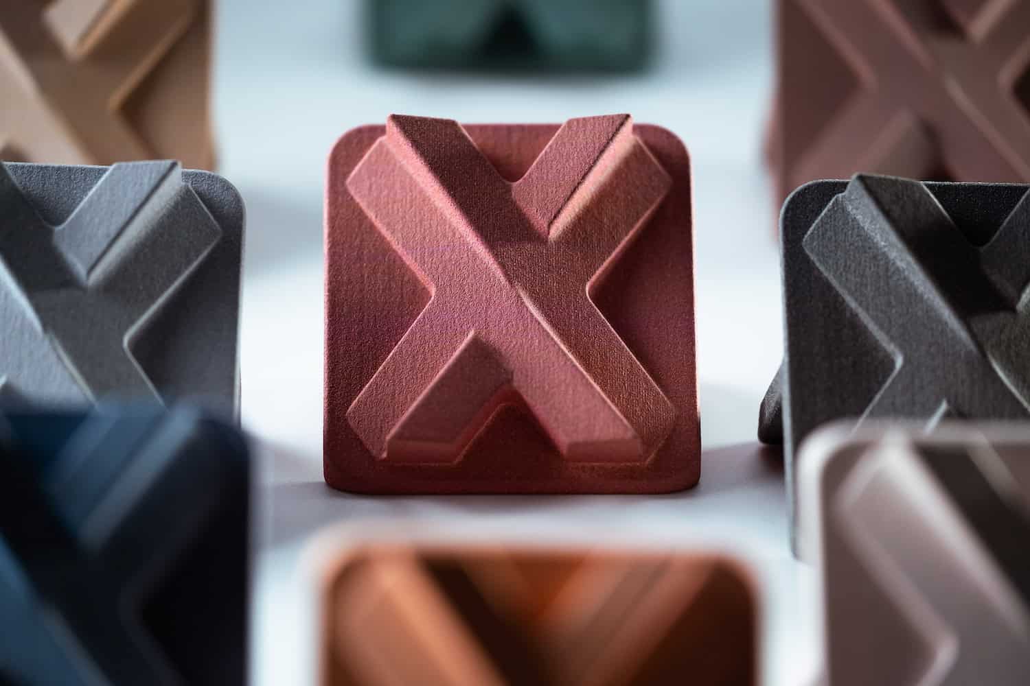
Multi Jet Fusion (MJF) is a powder-bed fusion technology developed by HP that uses heat and chemical agents to produce detailed, high-strength plastic parts. Unlike extrusion-based methods, MJF creates dense, isotropic parts with excellent surface finish and mechanical performance, making it well-suited for both functional prototyping and industrial production.
MJF offers many advantages: fast build speeds, precise detail resolution, and the ability to produce complex geometries without support structures. It is also one of the most cost-efficient options for medium to high-volume production, thanks to its efficient nesting and short cooling times. Common materials include PA 12, PA 11, polypropylene, and TPU—each selected for their durability, flexibility, and heat resistance.
1. Maintain Proper Wall Thickness
Walls that are too thin may deform or become brittle, while overly thick walls can lead to heat accumulation during printing and cause warping or uneven cooling. These problems are especially critical in MJF due to the thermal dynamics of powder-bed fusion.
Sudden variations in wall thickness can also generate internal stress, impacting dimensional accuracy and structural performance—especially on flat surfaces or large parts.
Rule of Thumb:
- Design walls at least 0.7 mm thick for PA 12, and up to 2.0 mm for more rigid materials.
- Walls as thin as 0.6 mm are possible with internal support, but 1.3 mm is preferred for consistent results.
- Avoid walls thicker than 7 mm, as excess material can cause internal stress and distortion.
- Maintain uniform wall thickness across the part to reduce warping risks.
- Add ribs or fillets to reinforce thin areas and distribute stress more evenly.
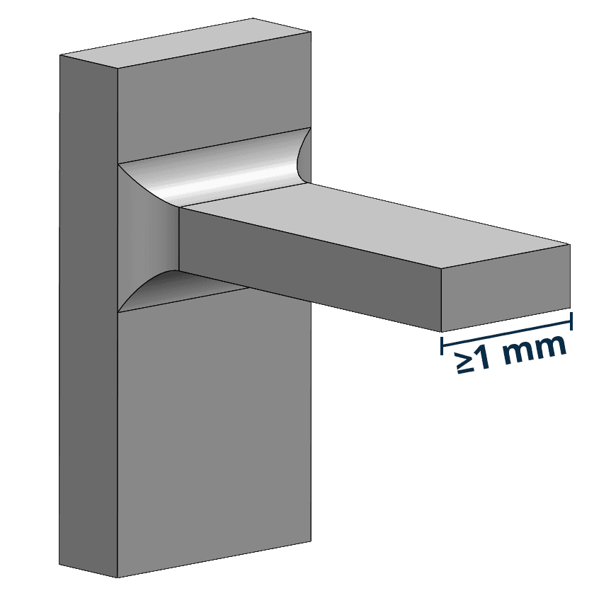
2. Reinforce Long and Thin Features
Slender features like cantilevers, hooks, or clips are particularly vulnerable in MJF. Without proper reinforcement, they may bend, snap, or warp due to unsupported geometry or concentrated stress.
This risk increases with high aspect ratios or sharp transitions, especially in the Z direction, where MJF parts are more exposed to uneven heating and cooling.
Rule of Thumb:
- For cantilevers with width < 1 mm, keep the aspect ratio (L/W) < 1.
- Use a minimum cantilever base thickness of 1 mm for durability.
- Add fillets or ribs at stress points or extended features.
- Avoid sharp edges and use smooth, gradual transitions to minimize mechanical stress.
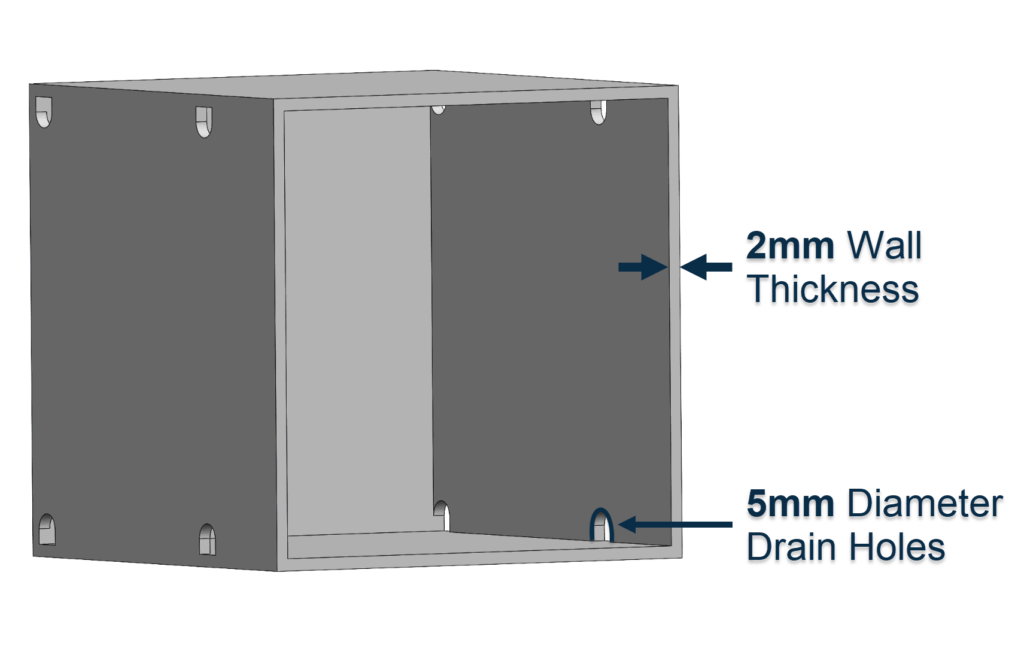
3. Optimize Hollow and Internal Structures
Enclosed spaces such as hollow bodies, ducts, or lattices tend to trap unfused powder. Without proper drainage, the trapped material increases part weight and complicates post-processing, especially for complex geometries. If unaddressed, this can lead to poor surface quality or blocked ducts—making the part unusable or harder to clean.
Rule of Thumb:
- Include two or more drain holes (each ≥ 5 mm) on opposite sides of hollow parts.
- Keep a minimum lattice beam gap of 1 mm for effective powder evacuation.
- In ducts, add a strip or chain feature to aid post-print powder removal.
- For ducts narrower than 5 mm, use a flexible cleaning tool after printing.
- Maintain 2–3 mm wall thickness in hollowed parts and include perforations if fully enclosed.


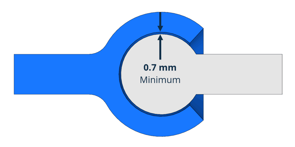
4. Allow for Proper Part Clearance
Parts designed to fit, slide, or rotate together must include sufficient clearance. If spacing is too tight, surfaces may fuse during printing or misalign after assembly. Because MJF does not account for mechanical tolerances or friction in digital models, designers must compensate with functional gaps based on real-world behavior.
Rule of Thumb:
- Parts printed together: minimum clearance of 0.7 mm.
- For post-assembly: use 0.4 mm clearance, or 0.2 mm for snug fits.
- If walls are < 3 mm thick, gaps as low as 0.3 mm may work, but require testing.
- Align parts in CAD to reflect real assembly positioning.
- Add drawings or notes to flag movable parts during post-processing.
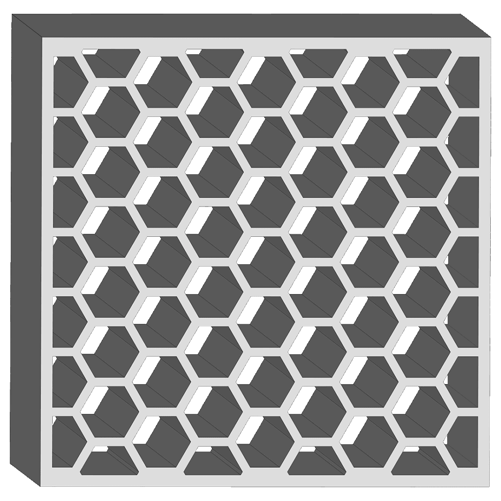
5. Avoid Large Flat Surfaces
Flat, wide surfaces—especially those printed parallel to the build plane—tend to warp due to uneven heat distribution and shrinkage. Adding support ribs may worsen the issue by concentrating stress. Warped surfaces reduce dimensional accuracy, create cosmetic defects, and may impair the part’s functional fit.
Rule of Thumb:
- Avoid large, flat surfaces (e.g., A4-sized planes) when possible.
- Replace broad areas with lattices, cutouts, or ribs to reduce thermal stress.
- Keep flat areas close to the bottom of the build to minimize Z-axis effects.
- Maintain a minimum thickness of 0.3 mm in wide areas to avoid curling.
6. Minimize Warping on Long Parts
Thin, elongated parts are especially susceptible to shrinkage and distortion. When one area cools faster than another, internal tension builds up and causes the part to warp—especially with abrupt changes in section thickness. This deformation often results in bends, uneven edges, or parts that fall outside dimensional tolerances.
Rule of Thumb:
- Avoid aspect ratios greater than 10:1 (length vs. width) in unsupported sections.
- Increase wall thickness to balance cooling on long features.
- Use smooth transitions to avoid stress from sudden geometry changes.
- Hollow out or use internal lattices to ensure more even material distribution and cooling.
7. Design Snap-Fits with MJF in Mind
Snap-fits are a simple way to assemble plastic parts, but require careful sizing to ensure flexibility and avoid breakage. If the overhangs are too sharp or the beam too rigid, it may snap during assembly.
Designing for MJF means understanding how the material flexes and where to relieve stress during engagement.
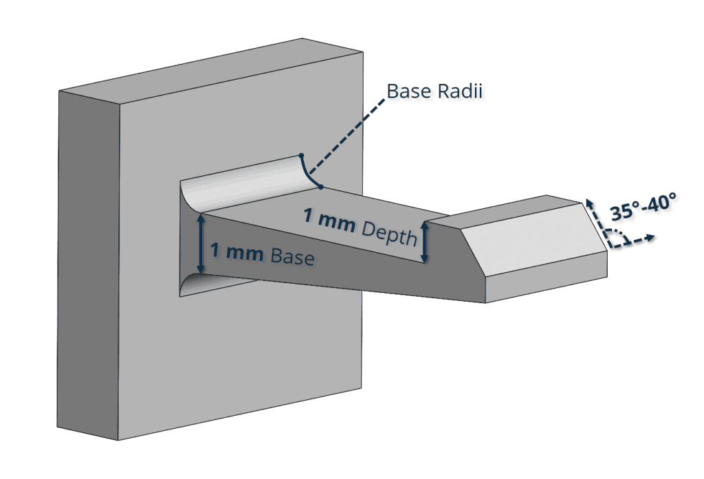
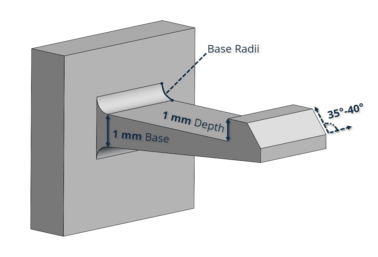
Rule of Thumb:
- Base thickness: ≥ 1 mm for the cantilever.
- Overhang depth: ≥ 1 mm for secure locking.
- Add radii = ½ base thickness at the root to distribute strain.
- Chamfer the tip of the overhang to reduce insertion force.
- Keep assembly angle between 35° and 40° and taper beams to reduce stress.
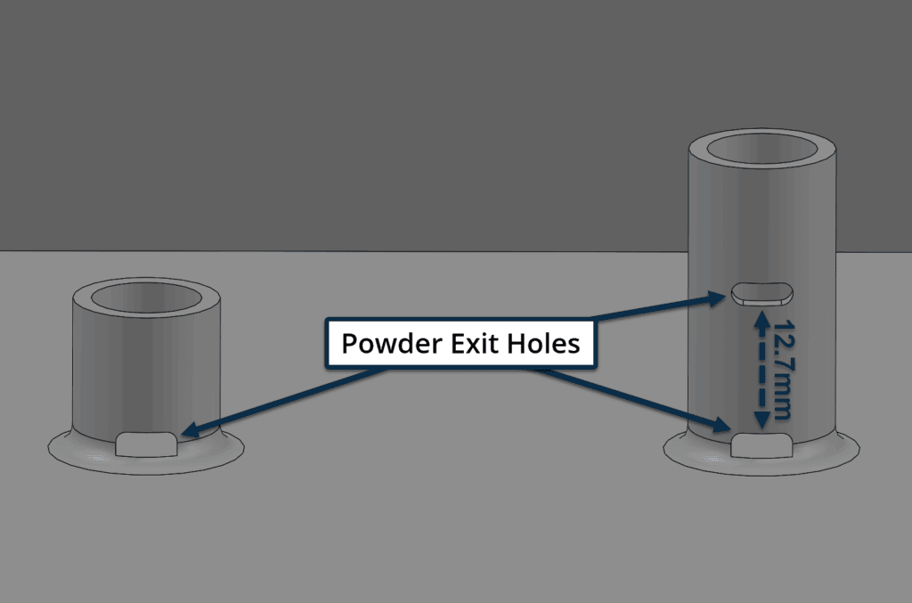
8. Avoid Deep Blind Holes Without Powder Escape
Blind holes, screw bosses, or deep cavities can trap powder if there’s no way for it to escape. The deeper the hole, the harder it is to clean—often requiring manual intervention.
Residual powder in threaded holes or sockets can block fasteners or weaken the structure if left in place.
Rule of Thumb:
- Add exit holes or escape channels with clear lines of sight.
- For deep holes (> 12.7 mm), include multiple exit points along the depth.
- Use fillets at the base of bosses to strengthen the feature and reduce stress.

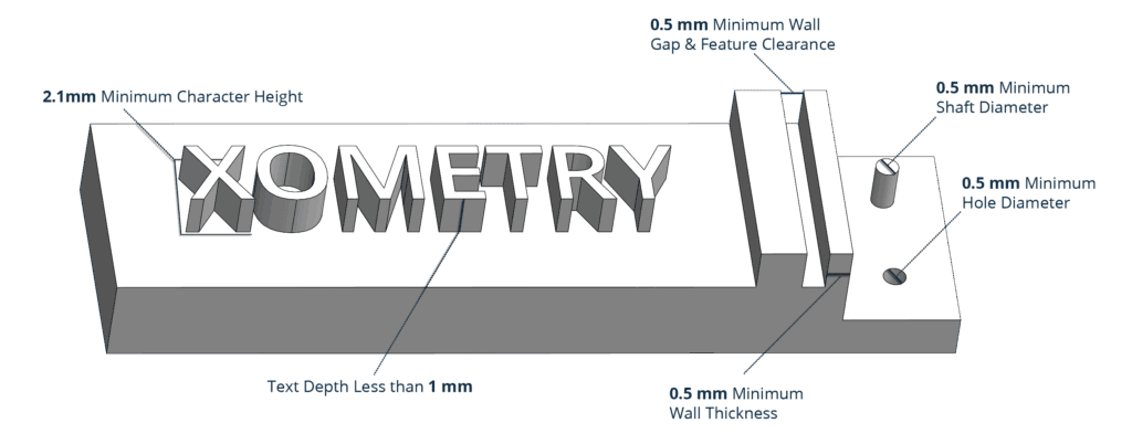
9. Use Legible Embossed and Engraved Details
Texts, logos, and surface features are often used for branding or part identification, but if they’re too small, they can blur during printing or disappear during post-processing. Embossed features are especially sensitive to surface treatments like bead blasting and vapor smoothing, which can round off edges and reduce definition.
Rule of Thumb:
- Use a minimum line thickness of 0.5 mm for both embossed and engraved features.
- Embossed: ≥ 1 mm height; Engraved: ≥ 0.5 mm depth.
- Ensure overall character height is at least 2.5 mm for good readability.
- For best results, orient embossed text face-down, and engraved text face-up.
Avoid raised or engraved features smaller than 0.5 mm, as they may not survive post-processing.
MJF 3D Printing Specifications Reference Guide
The following table shows specifications for designing parts to be 3D printed through the MJF printing technology.
| Specifications | Details |
| Maximum build volume | 380 x 284 x 380 mm. Recommended: 356 x 280 x 356 mm |
| Minimum feature thickness | 0.50 mm |
| Suggested minimum wall thickness | 0.70 mm (supported), 0.70 mm (unsupported) |
| Layer thickness | 0.08 mm |
| General tolerance | ±0.3% (± 0.3 mm) |
Get Your High-Quality MJF 3D Prints at Xometry
Designing effectively for MJF 3D printing means understanding the technology’s specific constraints and opportunities. By applying the right design practices—such as maintaining consistent wall thickness, adding drainage to enclosed features, ensuring proper part clearance, and optimizing part orientation—you can reduce the risk of common defects like warping, trapped powder, or surface inconsistencies.
At Xometry, our engineering team supports you in applying these design principles to help achieve reliable, functional parts suited to your specific application. Explore our MJF 3D printing service to see how it can support your prototyping or production needs.


Comment(0)