Europe
  Türkiye
  United Kingdom
  Global


Forum Replies Created
-
 Manon Bouriaud17.03.2025 at 11:43Senior Content Manager
 Hello, and thank you for your question! For your disc to be manufactured with precision, it is ideal to provide a precise CAD file (STP) along with a technical drawing detailing critical dimensions and tolerances. Here’s a helpful guide to properly prepare your technical drawing. If you have specific requirements for the finish, also remember to indicate the desired roughness, especially with a concave curvature like yours. This guide can help you better understand the impact of the surface. And it doesn’t matter if you’re an individual, as long as your request is well prepared, you’ll get a precise and tailored quote.Automatically translated from: FrançaisSee original0in reply to: Moulding of a Concave Disk
 Manon Bouriaud05.08.2024 at 10:59Senior Content Manager
Hello Benjamin,
Do you have a question to ask? It seems that your message has been truncated, and in its current state it is not very useful to the Community.Automatically translated from: FrançaisSee original0in reply to: MEI industry pieces
Manon Bouriaud18.06.2024 at 16:50Senior Content ManagerHello adrimeca,
There is not a wide choice of 3D printing materials that can withstand such temperatures. Do you want to make a piece in plastic or metal? Here are some material suggestions that might work:
- Plastics
- ULTEM 1010 is probably the best option for plastic materials, with a temperature resistance up to 216°C. It is compatible with FDM (Fused Deposition Modelling) 3D printing technology
- CE 221 has an even higher resistance (over 220°C) but Carbon’s DLS technology is still expensive, especially compared to FDM
- Metals – I’d recommend the following materials for 3D metal printing (DMLS)
- Aluminium AlSi10Mg
- Stainless steel 316L
- Inconel 718
I would say that aluminium AlSi10Mg remains the most viable option considering your requirements. I hope this answer will be useful to you!
Automatically translated from: FrançaisSee original0in reply to: Material for high temperature applications
Manon Bouriaud12.06.2024 at 10:43Senior Content ManagerHi Zdenek,
To complete Niko’s answer, you can check this detailed article about flame retardant materials https://xometry.pro/en-eu/articles/flame-retardant-plastics-ul-94/ You’ll find a list of materials which are, for most of them, UL 94 V-0 rated.
I also would like to bring your attention to the fact that depending on your application, V-0 rating might not be necessary and you could consider V-2 or V-1 (or maybe even HB) rated materials. The grade of flame retardancy should be chosen based on the part, its application, and the environment in which it will be used.0in reply to: Flame retardant materials for CNC machining
Manon Bouriaud23.05.2024 at 12:11Senior Content ManagerHello,
Thank you for your question, I’m sure it will be useful to other engineers.
Unfortunately, I do not have the answer at the moment. But the good news is that we have a wide network of partners and people we have asked for help to bring you an answer as soon as possible.
Thank you for your patience!Automatically translated from: FrançaisSee original0in reply to: Suspension
Manon Bouriaud15.05.2024 at 16:52Senior Content ManagerAnton HurynActually, we also have a transparent injection moulding card sample. Check it out:
1in reply to: Translucent material recommendation – injection molding
1
Manon Bouriaud03.05.2024 at 11:13Senior Content ManagerHello,
Unfortunately, I do not have expertise in robotics, but I can nonetheless recommend metal 3D printing (also called DMLS), it is the technology that will allow you to make the most resistant parts in 3D printing. As for the material, stainless steel 316L is the one with the best mechanical properties.
I hope this answer is useful to you anyway!Automatically translated from: FrançaisSee original0in reply to: ROBOT ARM
Manon Bouriaud04.04.2024 at 17:24Senior Content ManagerTechInventorXAnd if you want to read more on this topic, you can have a look at this article: https://xometry.pro/en-eu/articles/3d-printing-water-resistant/
0in reply to: Waterproof 3D print for test experiment
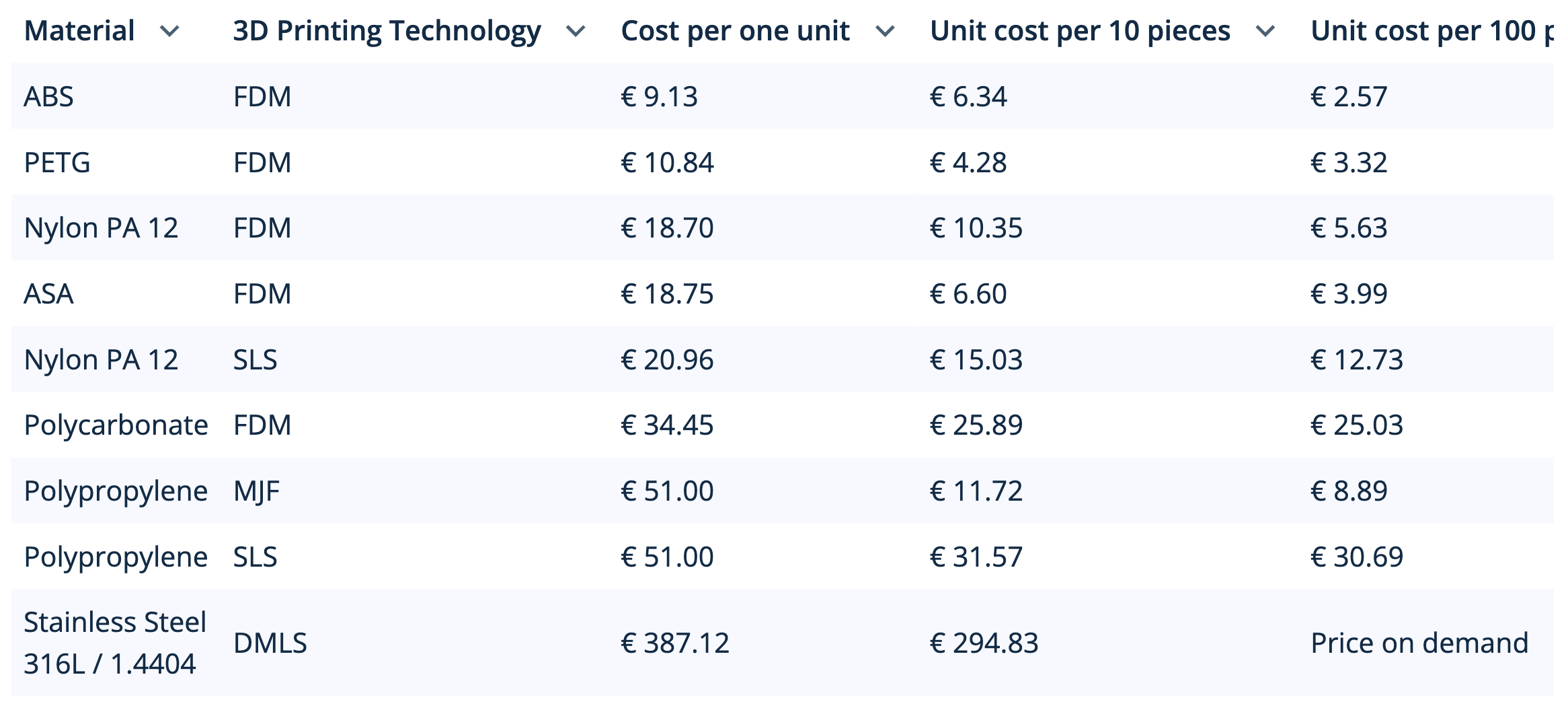
Manon Bouriaud04.04.2024 at 16:43Senior Content ManagerAttila SzucsTo jump back on Attila’s feedback, I invite you to check out this table below – we compared the prices of several water-resistant materials in our Instant Quoting Engine:

So, according to this table, PETG remains a good option for your experiment if you don’t want to spend too much money. But actually, I think ABS could be even better, because, as Attila mentioned, it can be vapour smoothed to ensure its waterproofness.1in reply to: Waterproof 3D print for test experiment
1
Manon Bouriaud04.04.2024 at 16:09Senior Content ManagerHello TechInvertorX, If you’re looking for material that doesn’t absorb water, I agree with Simon, you can consider using PETG. Polycarbonate, or certain types of Nylon could also be a good fit since they are specifically treated for low moisture absorption. I would say Polypropylene is one of the best options though – it is a popular material for food packaging bottles and containers. But it might be more expensive, especially for prototyping a single of a few parts.
-
This reply was modified 1 year, 11 months ago by
 Manon Bouriaud.
2in reply to: Waterproof 3D print for test experiment
2
Manon Bouriaud03.04.2024 at 15:15Senior Content ManagerHi Daan, to give you a comprehensive overview, I also recommend checking out a video we’ve created on vapor smoothing. It’s quite informative and visually demonstrates the process and its effects on 3D printed parts. You can watch it here: https://youtu.be/1LoPp8gc5yI?si=O8LgbiTRYpdwsAW9
We also ran a few experiments on 3D prints and it turned out that you can achieve a much smoother surface without affecting the parts’ dimensional accuracy with vapor smoothing. We have an in-depth article on this finishing process, you can have a look here: https://xometry.pro/en-eu/articles/3d-printing-vapor-smoothing/
0 Manon Bouriaud29.03.2024 at 17:02Senior Content ManagerRobert400Absolutely, happy to help! Choosing the right layer thickness for FDM really depends on your specific goals for the prototype:
- 0.1 mm or 100 µm (Fine) –for high-detail prints with more intricate details and superior finish quality, but with longer print times
- 0.2 or 200 µm (Standard) – it is a quite balanced option between speed and detail, and it’s suitable for a large variety of prints
- 0.3 or 300 µm (Economy) – this is the fastest option, where speed is clearly prioritized, but the layer lines will be much more visible. But it is suitable for rough prototypes

Hope this helps!-
This reply was modified 1 year, 11 months ago by Manon Bouriaud.
-
This reply was modified 1 year, 11 months ago by Manon Bouriaud.
-
This reply was modified 1 year, 11 months ago by Manon Bouriaud.
-
This reply was modified 1 year, 11 months ago by Manon Bouriaud.
0in reply to: Layer thickness for FDM and SLA
Manon Bouriaud29.03.2024 at 16:21Senior Content ManagerTechSavvyExactly, the scale of production and the prototyping stage’s dynamic nature are crucial factors. If you’re in the prototyping phase where changes are likely, vacuum casting provides the flexibility to make those adjustments without incurring significant costs. Injection moulding might be more economical for large-scale production due to lower costs per unit, but for a range like 30-50, vacuum casting often comes out on top in terms of cost and flexibility.
Also, keep in mind that vacuum casting prototypes often need a bit of extra work to get the finish just right, which could add time and cost. Plus, the silicone moulds used in vacuum casting don’t hold up as well as the metal moulds in injection moulding, especially if you’re making a lot of parts. This could impact your costs and how quickly you can get your prototypes ready.
If you’re keen on digging deeper into this topic, there’s a cool article comparing vacuum casting and injection moulding here: https://xometry.pro/en-eu/articles/vacuum-casting-vs-injection-molding/
0in reply to: Vacuum casting or injection moulding for 20-30 pcs?
Manon Bouriaud29.03.2024 at 16:01Senior Content ManagerWelcome to the forum! The layer height is the thickness of each layer that the printer lays down. For FDM (Fused Deposition Modeling), layer heights are typically between 0.1 to 0.3 mm, although they can go finer. Lower layer heights give you finer detail but at the cost of longer print times and potentially more failures.
As for SLA, the printers typically have finer layer heights compared to FDM, often ranging from 0.025 to 0.1 mm. SLA works by curing resin with a laser or light source, so it can achieve very fine details.
1in reply to: Layer thickness for FDM and SLA
1
Manon Bouriaud28.03.2024 at 17:53Senior Content ManagerZimonixIt’s sufficient to maintain structural integrity under normal conditions. But if your piece is intended for applications where it will be subjected to high mechanical stresses, I would recommend increasing the wall thickness to reinforce the robustness, for example to 1 mm or more, depending on your specific needs.
Automatically translated from: FrançaisSee original0in reply to: 3D Printing with Aluminum
Manon Bouriaud28.03.2024 at 17:42Senior Content ManagerHello! Yes, for AlSi10Mg aluminum, the minimum wall thickness we recommend is 0.4 mm, with support structures. Without a support structure, then we recommend a thickness of 0.5 mm to maintain the structural integrity of the part. However, this can vary depending on the machine and the specific printing conditions.
Automatically translated from: FrançaisSee original0in reply to: 3D Printing with Aluminum
Manon Bouriaud22.03.2024 at 15:11Senior Content ManagerIf you have other questions about the types of hole drilling, do not hesitate to consult this white paper on the subject. It contains all the main reference symbols to use on your technical drawings and common applications https://xometry.pro/fr/guides/livre-blanc-types-trous-ingenierie/
Automatically translated from: FrançaisSee original0 Manon Bouriaud19.03.2024 at 16:58Senior Content ManagerBy the way, here’s a link to an article with more details on food-grade 3D printing materials and technologies https://xometry.pro/en-eu/articles/3d-printing-food-safe/
0in reply to: Food contact safe manufacturing
Manon Bouriaud18.03.2024 at 14:01Senior Content ManagerYou can also check these two videos explaining the process of each of these two post-processing operations:
0in reply to: Anodising vs. powder coating
Manon Bouriaud15.03.2024 at 16:28Senior Content ManagerThe choice of material based on its characteristics is crucial, as not all react the same way to dyes. But the best solution is always to send a sample of the desired color to the supplier, at least for the first batch. And ideally, to keep the same supplier throughout production to ensure the uniformity of the parts and their color. I also invite you to read this article on the subject https://xometry.pro/fr/articles/moulage-injection-couleur/Automatically translated from: FrançaisSee original0in reply to: How to ensure color uniformity in plastic injection?
Manon Bouriaud14.03.2024 at 14:04Senior Content ManagerYou can also check this article that goes deeper into the topic of designing perfect technical drawing for CNC machining, or watch this video that combines all tips https://youtu.be/lb5i00DHGG8?si=onJzGBs1w6smHC2-
0in reply to: Tips for designing for CNC machining
Manon Bouriaud13.03.2024 at 17:40Senior Content ManagerFor parts intended for outdoor use, and for fused wire deposition, I recommend ASA. This material is very resistant, both to weather and to sun and aging due to UV rays. And it is available in many different colors. ABS is also a robust material, but its properties are not as good as ASA’s when it comes to outdoor conditions. Otherwise, PETG can be a good alternative. It is robust and offers good resistance to UV rays. And it can be found in various colors. As for Nylon, and in particular PA12, it is indeed an excellent material with good mechanical properties, but preferably with SLS technology (or MJF if we stick to powder bed technologies). Associated with fused wire deposition, PA12 is not as resistant.Automatically translated from: FrançaisSee original0in reply to: Best FDM Materials for Outdoor Use
Manon Bouriaud13.03.2024 at 10:23Senior Content ManagerStainless steel 316L can also be an alternative to Inconel 718, with a melting point of 1,400°C (1,430°C for Inconel). Stainless steel has a lower tensile strength though. If you are considering 3D printing, you can check this article that compares the best heat-resistant materials (both metals and plastics) https://xometry.pro/en-eu/articles/3d-printing-materials-heat-resistant/
0in reply to: Material for high-temperature applications
- Plastics