 Europe
  Türkiye


What Is Multi Jet Fusion 3D Printing?
MJF technology works by selectively applying fusing and detailing agents to powder layers (such as Nylon, TPU, or PP) using an inkjet array, which is then rapidly fused by infrared heating elements.
Because the energy is applied across the entire build surface simultaneously, MJF can achieve significantly faster production speeds than point-based laser processes. The surrounding unfused powder naturally supports overhanging features, enabling complex geometries without dedicated support structures.
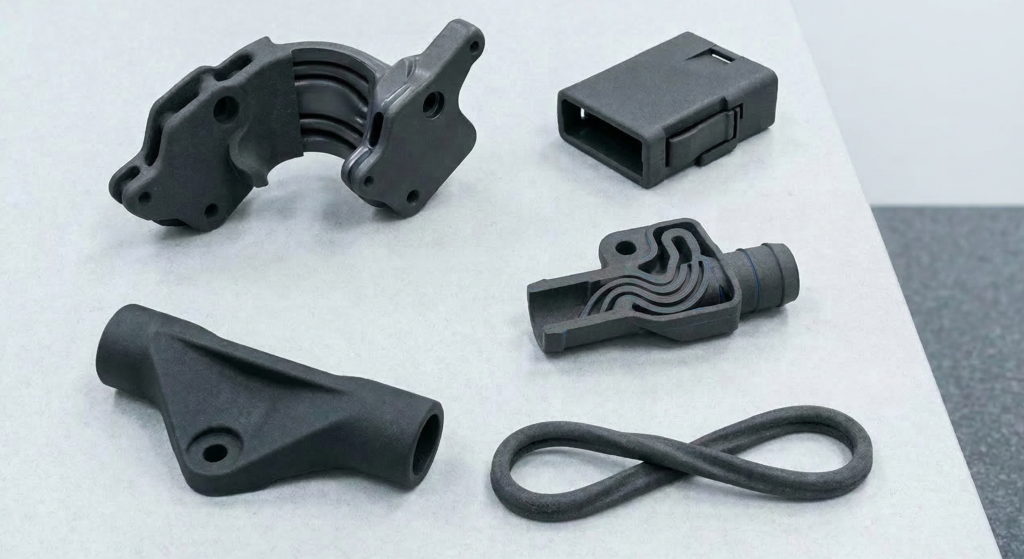
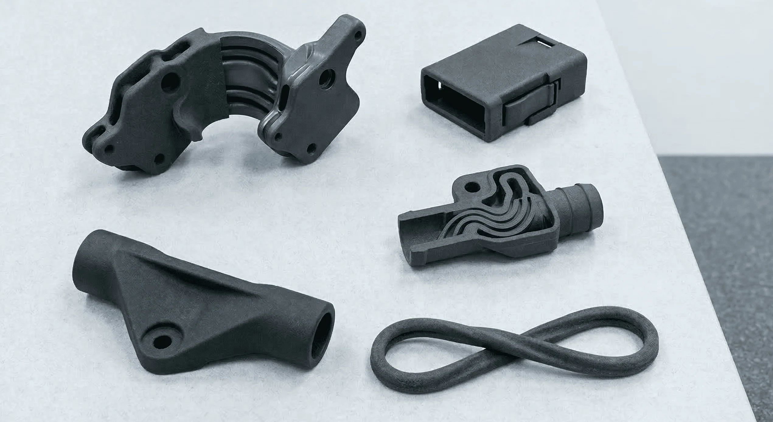
Today, MJF is widely used for manufacturing functional nylon components, engineering prototypes, and short-run production parts with complex geometries.
How Does MJF 3D Printing Work?
The MJF 3D printing process follows a precise, five-step cycle:
- Powder Deposition: A recoating system spreads a highly uniform layer of thermoplastic powder across the build platform.
- Agent Application: An inkjet array deposits a fusing agent onto the regions intended to solidify. Simultaneously, a detailing agent is applied along part boundaries to limit lateral heat spread and ensure crisp edges.
- Fusion: Infrared radiation sweeps across the entire build surface. Areas saturated with the fusing agent absorb this energy and melt, while regions with the detailing agent remain unfused. This repeats layer-by-layer.
- Cooling: The build undergoes a controlled cooling phase within the powder bed. Because the surrounding unfused powder supports overhanging features, MJF requires zero printed support structures.
- Post-Processing: The build block is moved to a processing station where unfused powder is vacuumed away. A massive advantage of MJF is that 80–85% of this recovered powder can be recycled for future builds.
Materials for Multi Jet Fusion
MJF materials can be split into two primary categories:
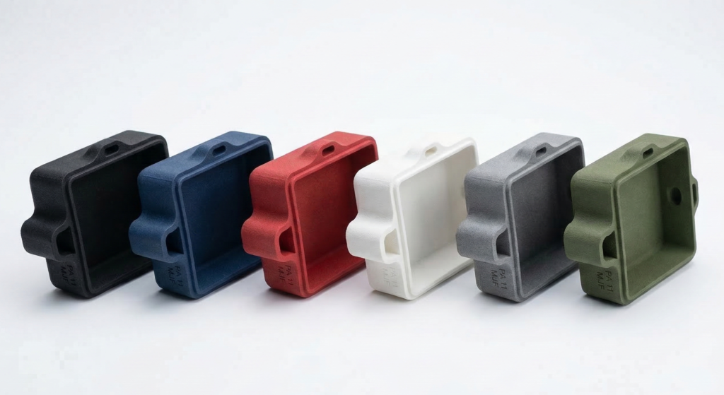
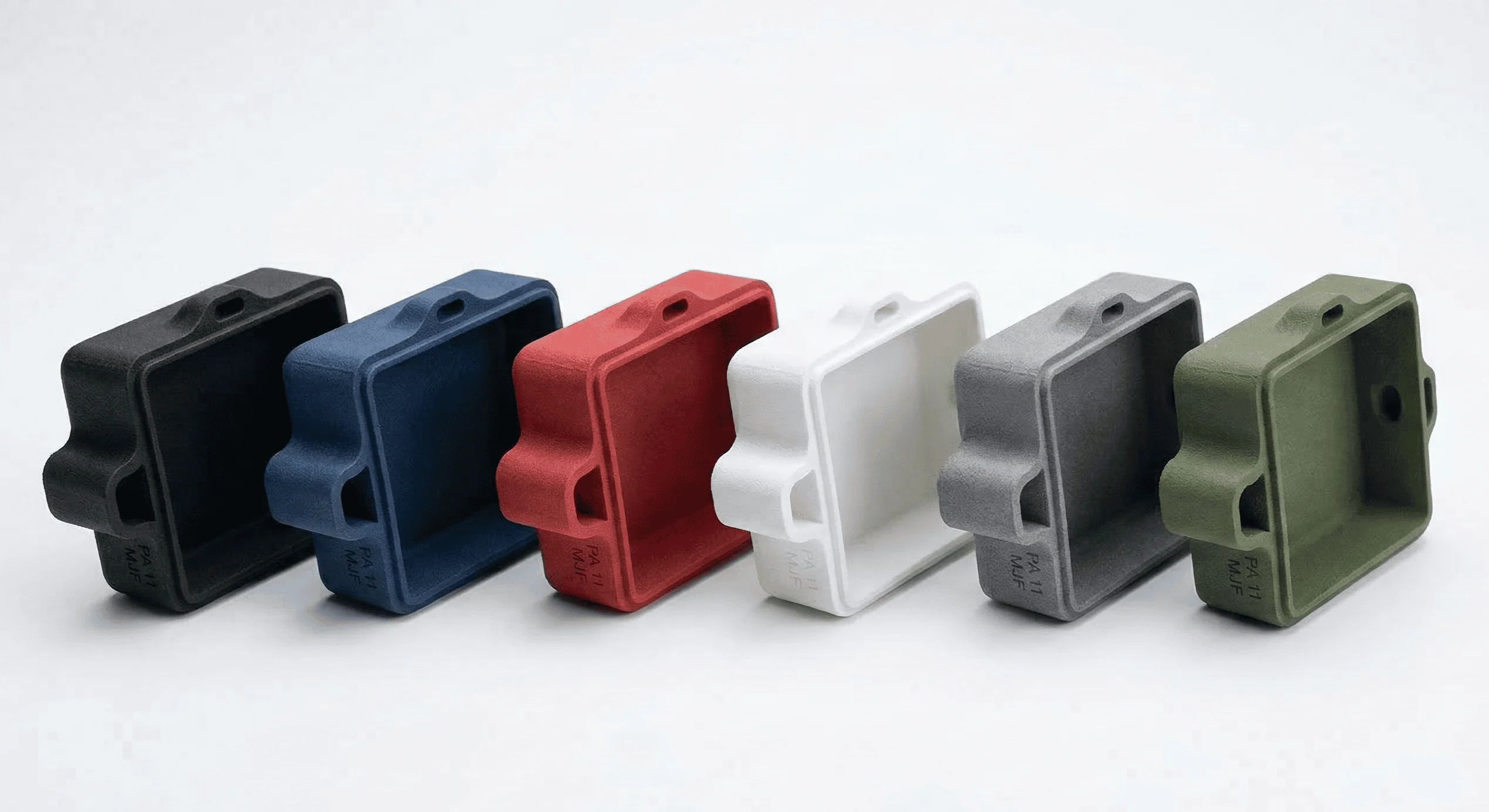
- Rigid plastics: Nylon PA 11, Nylon PA 12, and PP
- Flexible plastics: TPU (thermoplastic polyurethane)
The table below summarises most of the materials used in MJF 3D printing:
| Material | Description | XY, Z Tensile Strength | Shore Hardness | Use Case |
| PA 12 (Nylon 12) | Common MJF material with excellent strength, toughness, chemical resistance, and dimensional stability. | 48, 48 MPa | 80D | The industry standard. Used for functional prototypes, enclosures, and end-use parts. |
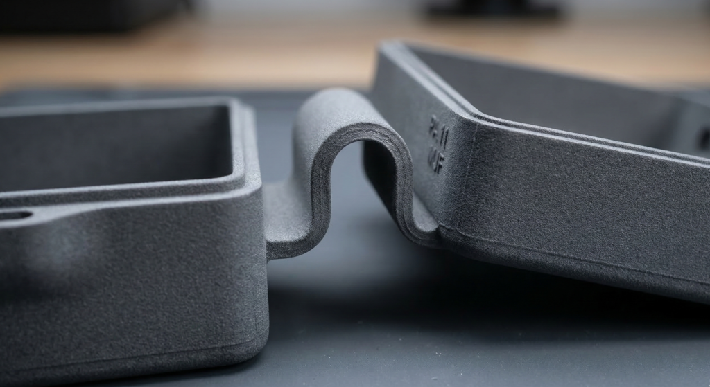
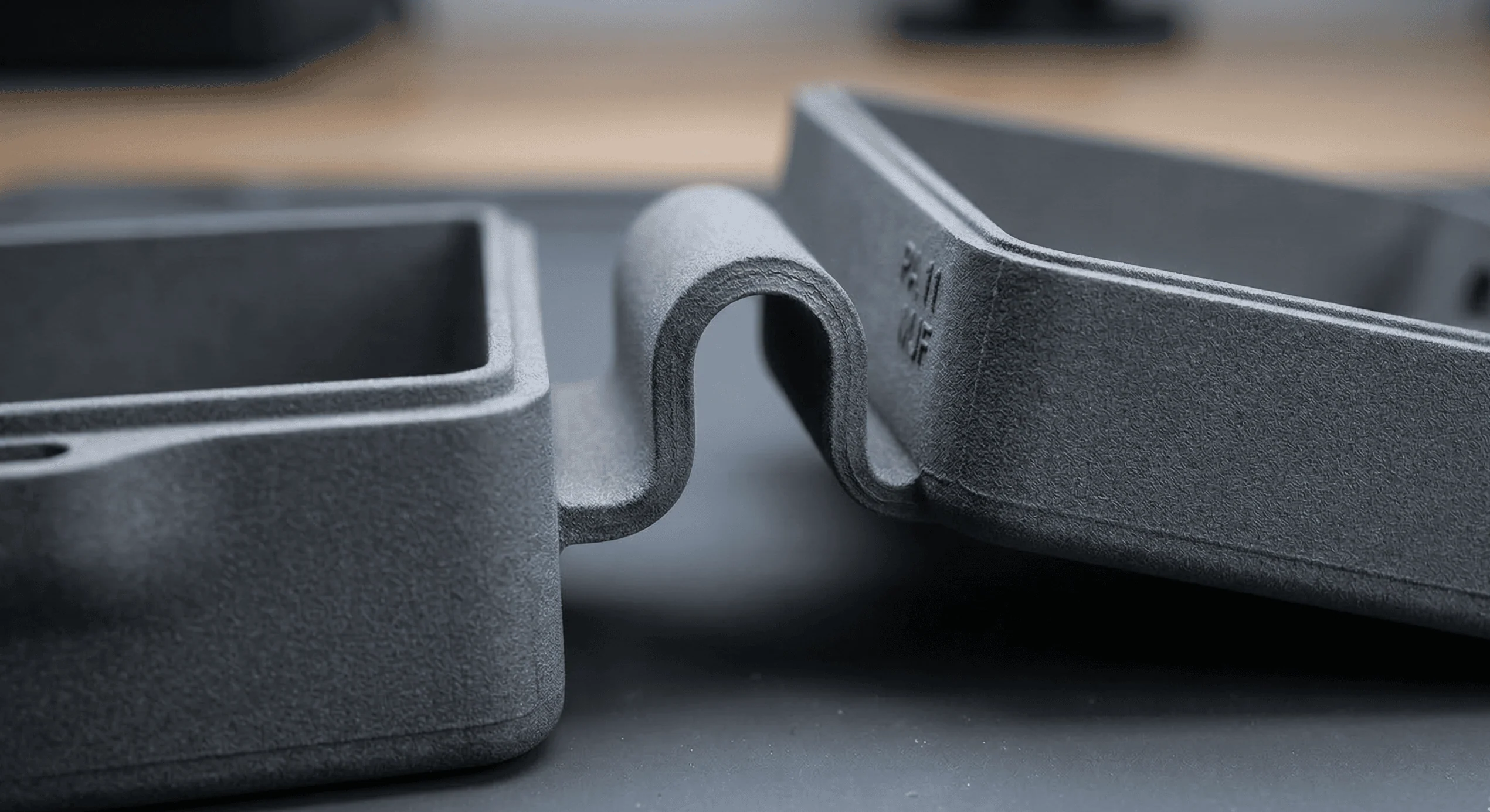
| PA 11 (Nylon 11) | Bio-based polymer with higher ductility and impact resistance than PA 12. | 52, 52 MPa | 80D | Bio-based polymer with superior ductility for snap-fit components and living hinges. |
| PP (Polypropylene) | Lightweight, chemically resistant thermoplastic with good impact strength, flexibility, low moisture absorption, and excellent fatigue resistance. | 30, 30 MPa | 70D (est.) | High chemical resistance and low moisture absorption for fluid-contact applications. |
| TPU (Thermoplastic Polyurethane) | Flexible, elastic material with good abrasion and fatigue resistance. | 9, 7 MPa | 88A | Flexible and elastomeric; ideal for seals, gaskets, and shock absorbers. |
| PA 12 (Nylon 12) Glass-Filled | Reinforced nylon with increased stiffness, improved thermal resistance, and reduced warping. | 30, 30 MPa | 82D | Glass bead reinforcement provides maximum stiffness and thermal resistance. |
For a comprehensive guide on the significance of Shore hardness ratings, kindly refer to our article, Shore Hardness for Plastics and Rubbers.
Post-Processing and Finishes for MJF
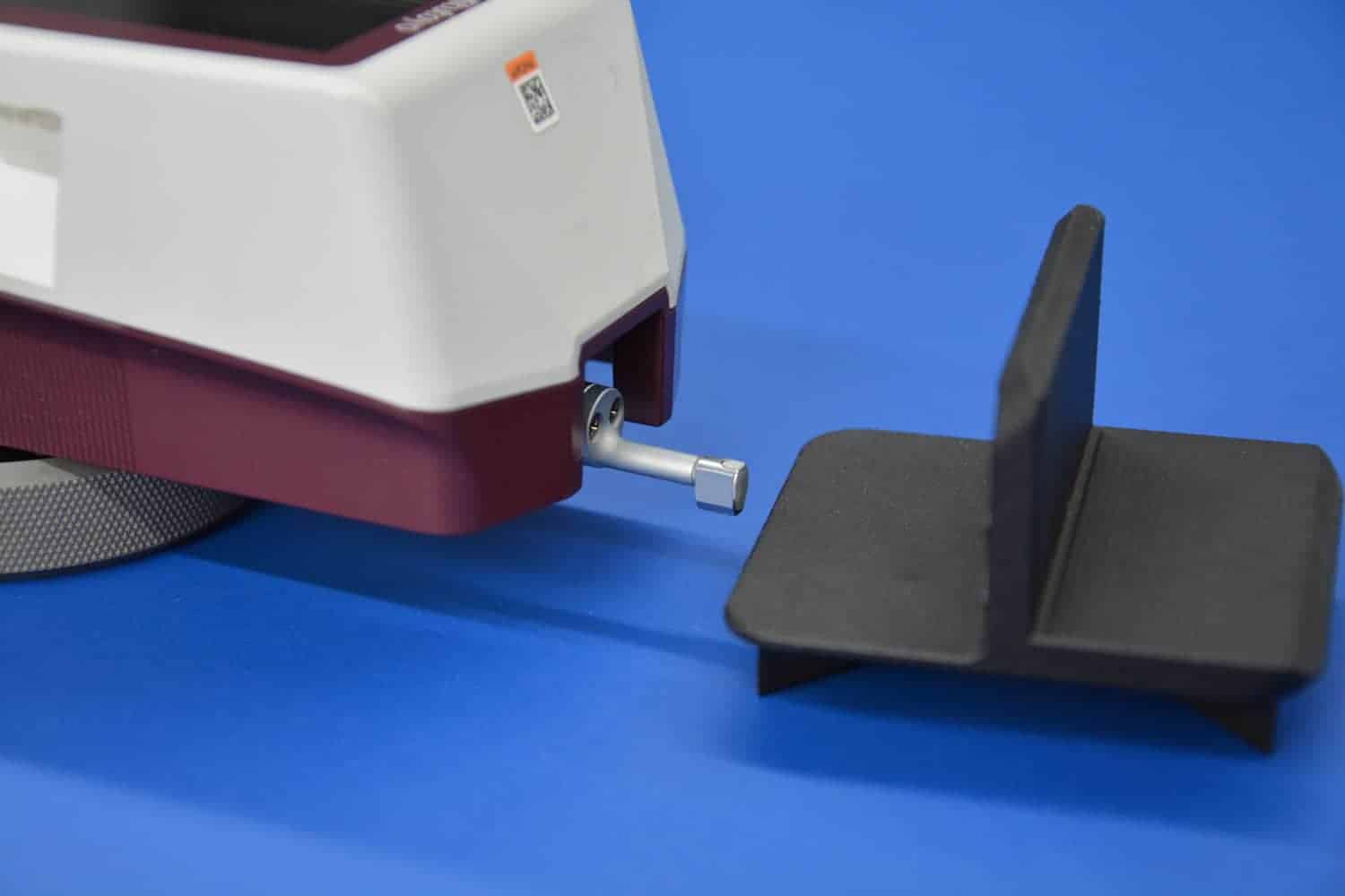
Standard MJF parts exit the powder bed with a matte, slightly grainy texture. To meet specific mechanical or aesthetic requirements, engineers specify secondary post-processing operations.
Some finishing processes, such as vapour smoothing, can also improve mechanical performance and reduce surface porosity.
The table below summarises the post-processing operations that can be performed on an MJF 3D printed part:
| Process | Purpose | Relative Cost |
| Depowdering and bead blasting | Removes unfused powder and cleans the surface | $ |
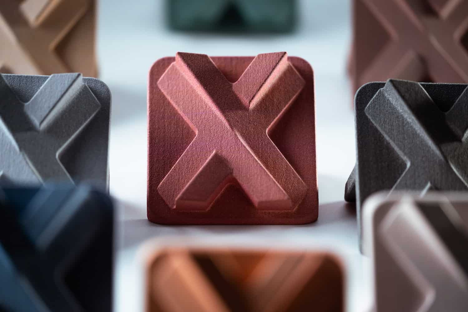
| Dyeing | Adds uniform color to porous nylon surfaces | $ |
| Vapour smoothing | Seals the surface and improves finish | $$$ |
| Media tumbling | Reduces roughness and creates a satin finish | $$ |
| Painting or coating | Improves appearance and environmental resistance | $$$ |
| Metal coating | Adds electrical conductivity or decorative finish | $$$ |
Advantages and Disadvantages of MJF 3D Printing
When evaluating MJF against other additive or traditional manufacturing methods, engineers must weigh its high throughput and isotropic strength against its inherent surface finish and material limitations
| Feature | Advantages | Disadvantages |
| Mechanical | Near-isotropic properties (97–98% isotropy) | Limited material library vs. SLS |
| Production | Faster cooling and high throughput | Higher initial equipment cost |
| Aesthetics | Smooth surface finish and crisp edges | Natural grey finish; requires dyeing for color |
| Design | No support structures needed | Minimum wall thickness constraints |
| Cost | No tooling; 80–85% powder reusability | Outsourcing needed if volume is low |
Key Advantages of MJF
- Near-Isotropic Strength: Unlike FDM, MJF parts exhibit nearly identical tensile strength in the X, Y, and Z axes (97–98% isotropy), making it one of the most mechanically consistent polymer processes available.
- High Productivity: Because the infrared lamp fuses the entire build area in a single pass, printing a full bed of parts takes nearly the same time as printing a single part.
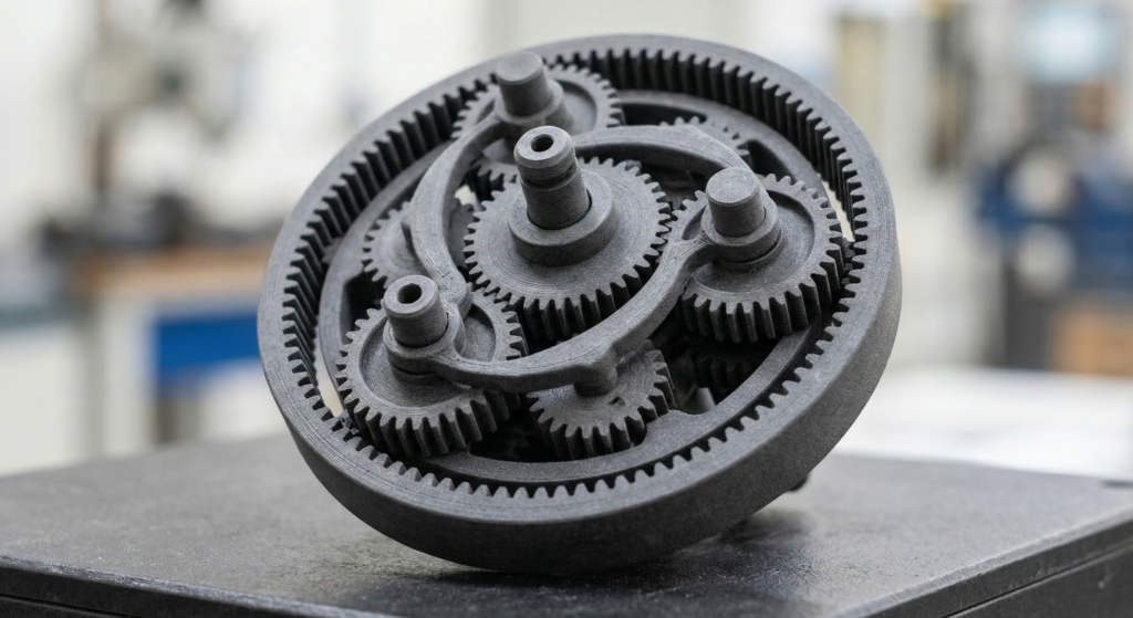
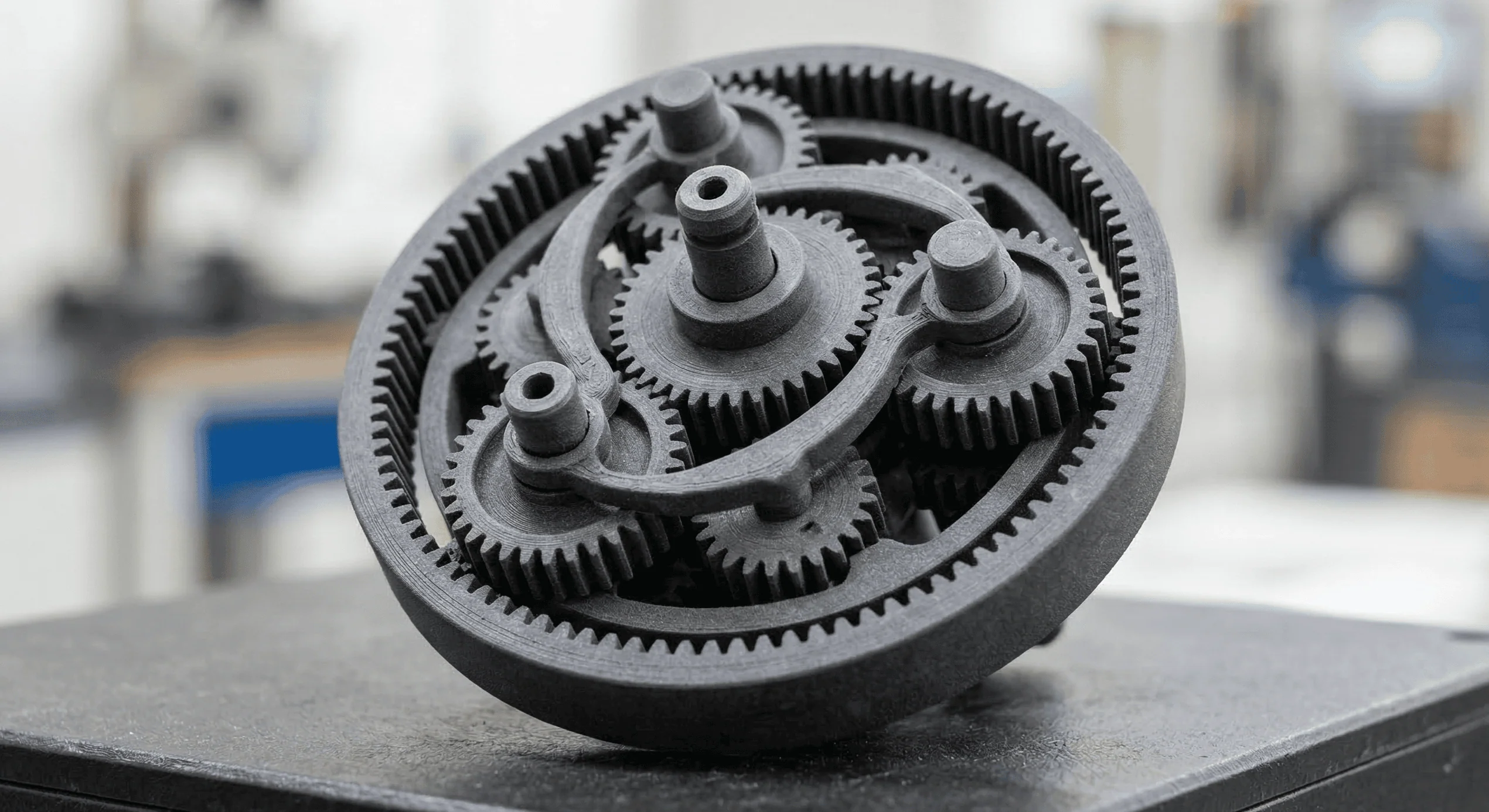
- Design Freedom: The unfused powder surrounding the part acts as a natural support system. This allows engineers to print complex internal channels and interlocking assemblies without manual support removal.
- Material Reusability: MJF achieves an 80–85% powder recycling rate after each build (compared to ~50% for SLS), significantly reducing waste and driving down per-part costs.
Rapid Lead Times: MJF achieves production-ready results in as little as 3 days, easily outpacing standard SLS or FDM workflows.
Key Disadvantages of MJF
- Color Limitations: Because the fusing agent contains carbon black, standard as-printed MJF parts are naturally charcoal grey. Achieving specific brand colors requires secondary painting or dyeing.
- Limited Polymer Portfolio: MJF is strictly limited to specific polymer powders (PA 11, PA 12, PP, and TPU). If you require specialty filaments like ULTEM, PETG, or ABS, FDM is required.
- Surface Texture: As-printed MJF parts possess a matte, slightly grainy texture that is rougher than SLA or PolyJet. Achieving injection-moulding smoothness requires secondary processing like vapour smoothing.
MJF Printed vs. Injection Moulded PA 12
| Tooling Cost | None | $3,000 to $100,000+ depending on mould complexity |
| Lead Time (First Part) | 3 to 7 days | 4 to 12 weeks including tooling fabrication |
| Design Change Cost | None. Reslice updated CAD file | Mould modification or replacement required |
For production runs under 1,000 units, MJF is fiercely competitive with injection moulding.

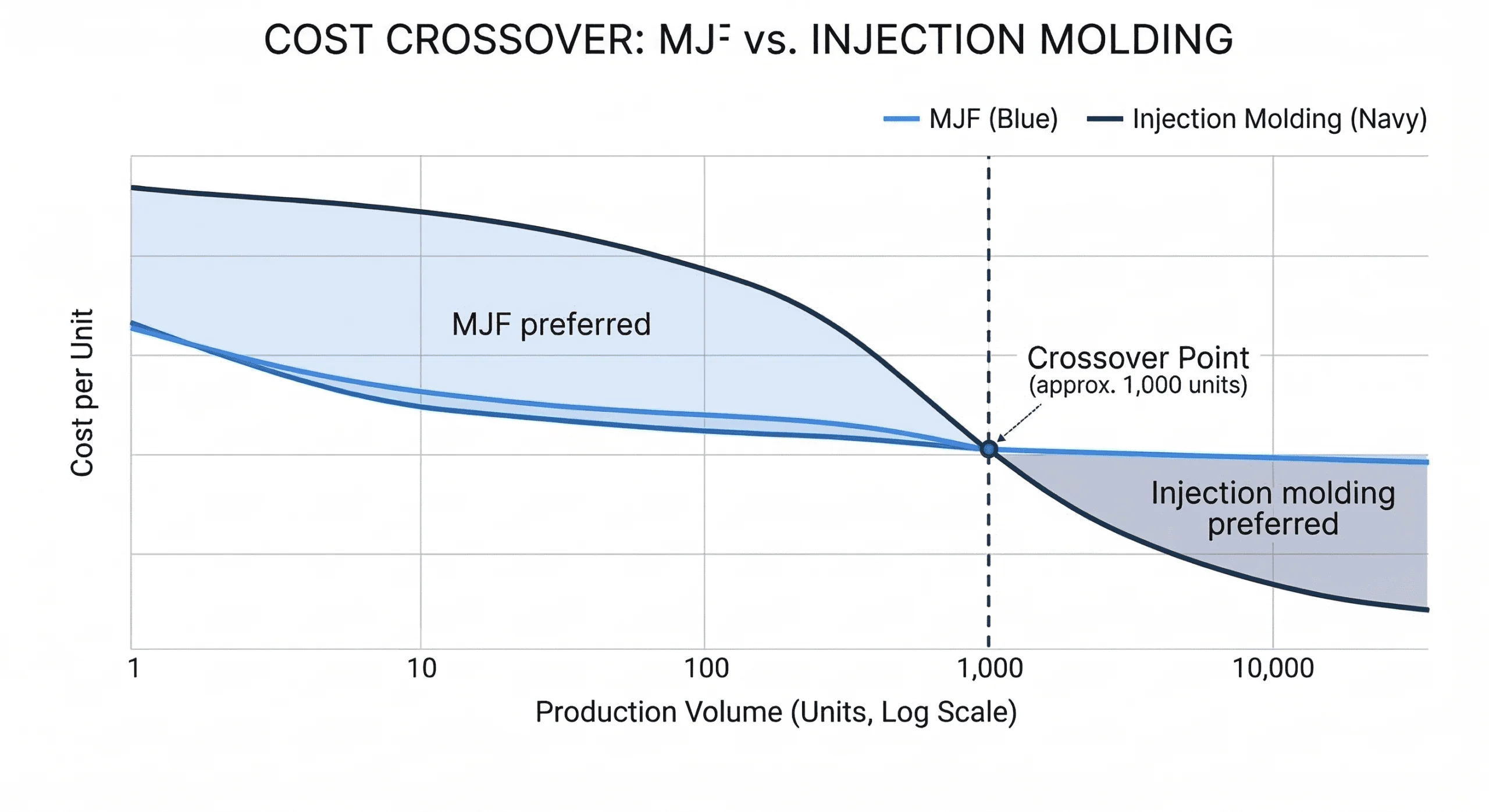
MJF-printed PA 12 matches or exceeds the tensile strength of moulded PA 12, with the distinct advantage of 97–98% isotropy (equal strength in all directions). However, injection moulding produces fully dense parts with submicron surface finishes, whereas MJF retains fine micro-porosity. MJF completely eliminates tooling costs and lead times, making it the superior choice for rapid iterations and bridge production.
| Property | MJF PA 12 | Injection Moulded PA 12 |
| Tensile strength | 48–52 MPa | ~42 MPa (yield, dry) |
| Tensile modulus | ~1.8 GPa | ~1.45 GPa (dry) |
| Isotropy | 97–98% | Anisotropic (skin-core) |
| Surface finish | Matte, slightly grainy | Smooth to submicron |
| Porosity | Fine micro-porosity | Fully dense |
| Ideal volume | 1–1,000 units (no tooling) | 1,000+ units (tooling amortised) |
Design Rules for MJF 3D Printing
Design Quick Reference Table
To leverage MJF’s complex geometric capabilities and prevent thermal warping, CAD files must be optimised according to these tolerances:
| Parameter | Minimum | Recommended | Notes |
| Feature size (X, Y, Z) | 0.5 mm | 1.0 mm+ | Features below 0.5 mm risk print failure or loss during depowdering |
| Wall thickness | 0.8 mm | 1.5 mm | Uniform thickness preferred throughout the part |
| Max solid wall section | — | 7 mm or less | Sections thicker than 7 mm should be hollowed to prevent sink marks |
| Drain hole diameter (hollow parts) | 4 mm | 5 mm | Minimum two holes on opposing faces for powder evacuation |
| Drain hole spacing (deep features) | — | Every 12.7 mm | Prevents powder accumulation in deep blind holes or bosses |
| Embossed / debossed text height | 1.5 mm | 2.1 mm+ | Shallower relief cleans better and produces crisper results after bead blasting |
| Moving joint clearance | 0.4 mm | 0.5 mm | Required for printed-in-place mechanisms to free after depowdering |
| Dimensional tolerance | ±0.3 mm | — | Add 0.1 to 0.2 mm machining allowance on critical mating surfaces |
For deeper design and material guidelines for MJF 3D printing, download our HP Multi Jet Fusion Design Guide eBook.
Multi Jet Fusion Compared to Other 3D Printing Processes
Selecting a 3D printing process involves compromises between performance, finish, throughput, materials, and production volume.
MJF is often selected for low- to mid-volume production of functional polymer components where tooling-based manufacturing is not cost-effective.
The table below compares common 3D printing processes:
| Requirement | Recommended Technology |
| Functional nylon parts with complex geometry | MJF / SLS |
| Smooth cosmetic surfaces | SLA / PolyJet |
| Large thermoplastic parts at low cost | FDM |
| High-volume plastic production | Injection moulding |
| Metal parts | DMLS / SLM |
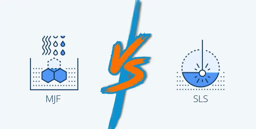
MJF vs SLS
Both MJF and Selective Laser Sintering (SLS) are powder-bed fusion technologies capable of producing functional nylon components without support structures.
However, the technologies differ in how energy is applied.
| Feature | MJF | SLS |
| Energy source | Infrared + fusing agent | Laser |
| Production speed | Faster for packed builds | Slower for large builds |
| Mechanical properties | Near-isotropic | Slightly anisotropic |
| Material range | Smaller | Wider |
FAQs
What is the difference between MJF and SLS?
Both are powder-bed fusion processes. However, SLS uses a laser to sinter cross-sections point-by-point, whereas MJF uses an inkjet array and infrared lamps to fuse entire layers instantly. MJF provides higher throughput, better isotropy (97–98% vs. ~85–90%), and higher powder reusability (80–85% vs. ~50%). SLS generally offers a wider portfolio of specialty materials.
What materials can be used with MJF?
MJF is compatible with HP-certified polymer powders: PA 12 (Nylon 12) for strength and chemical resistance, PA 11 (Nylon 11) for higher ductility, PA 12 Glass Beads for improved stiffness, PP (Polypropylene) for chemical resistance, and TPU for flexible, shock-absorbing parts. PA 12 is the most commonly used MJF material.
How accurate is MJF 3D printing?
MJF routinely achieves dimensional tolerances of ±0.3% (with a lower limit of ±0.3 mm). The machines print at 1,200 DPI with a layer thickness of 80 microns (0.08 mm). Tolerances may vary depending on part size, geometry, and orientation in the build chamber.
Does MJF require support structures?
No. MJF is a powder-bed fusion process, meaning unfused powder supports the part during printing. This allows complex geometries and internal structures to be produced without dedicated support structures.
Can MJF parts be used as end-use production parts?
Yes. MJF is a production manufacturing process, not only a prototyping technology. MJF parts are used as end-use components in automotive interiors, medical devices, consumer electronics, industrial equipment, and aerospace ground support applications. The near-isotropic mechanical properties, consistent repeatability, and production throughput of MJF make it suitable for functional production parts in volumes from single units to approximately 1,000 units per run. Above that threshold, injection moulding typically becomes more cost-effective per unit, but MJF remains the right choice for geometrically complex parts or programs where design changes are still expected.


Comment(0)